EP0445451A1 - Processeur d'image pour produire des images non-corrompues - Google Patents
Processeur d'image pour produire des images non-corrompues Download PDFInfo
- Publication number
- EP0445451A1 EP0445451A1 EP90302406A EP90302406A EP0445451A1 EP 0445451 A1 EP0445451 A1 EP 0445451A1 EP 90302406 A EP90302406 A EP 90302406A EP 90302406 A EP90302406 A EP 90302406A EP 0445451 A1 EP0445451 A1 EP 0445451A1
- Authority
- EP
- European Patent Office
- Prior art keywords
- image
- staircase
- pixels
- logic
- line
- Prior art date
- Legal status (The legal status is an assumption and is not a legal conclusion. Google has not performed a legal analysis and makes no representation as to the accuracy of the status listed.)
- Withdrawn
Links
Images




Classifications
-
- G—PHYSICS
- G06—COMPUTING OR CALCULATING; COUNTING
- G06T—IMAGE DATA PROCESSING OR GENERATION, IN GENERAL
- G06T5/00—Image enhancement or restoration
- G06T5/70—Denoising; Smoothing
-
- G—PHYSICS
- G06—COMPUTING OR CALCULATING; COUNTING
- G06T—IMAGE DATA PROCESSING OR GENERATION, IN GENERAL
- G06T2200/00—Indexing scheme for image data processing or generation, in general
- G06T2200/12—Indexing scheme for image data processing or generation, in general involving antialiasing
Definitions
- the invention relates to an image processor for producing anti-aliased images.
- Staircase aliasing is the effect which can be observed on lines and edges which are at an angle to the horizontal and vertical directions on a pixel-based display such as a raster-scanned visual display device or a matrix printer.
- This invention is directed to reducing staircase aliasing and does not specifically address other aliasing problems such as the Moire patterns associated with sampling aliasing.
- Anti-aliasing is a technique which reduces this effect as perceived when viewing the displayed image by adjusting the intensity of the displayed pixels along the line or edge. It has been proposed to perform anti-aliasing at various times and in various ways during the generation of the images for display.
- the anti-aliasing can be performed on each edge and/or line as it is generated. Anti-aliasing in this manner can be termed pre-filtering. This can be performed by a technique termed "supersampling", where extra values are calculated and then averaged. This and other pre-filtering approaches, are, however, expensive in terms of processing time.
- Anti-aliasing after an image has been created can be termed post-filtering. This technique has the disadvantage, however, of blurring the image too much with the result that even horizontal and vertical lines become blurred.
- an image processor for processing pixel data defining an image and comprising image processing logic for detecting pixel data representing stepped chrominance and/or luminance transitions characteristic of staircase aliasing in the image and for producing an output image including anti-aliasing on the detected stepped transitions.
- an image processor in accordance with the invention is able to give much better results than can be achieved with conventional convolution filtering while still performing post processing of a source image.
- the image processing logic comprises staircase point detection logic for detecting a staircase point at which there is step in a chrominance and/or luminance transition from a first or a second side of a line of pixels to the opposing side of the line of pixels, where the line of pixels is a row or a column of image pixels.
- staircase point detection logic for detecting a staircase point at which there is step in a chrominance and/or luminance transition from a first or a second side of a line of pixels to the opposing side of the line of pixels, where the line of pixels is a row or a column of image pixels.
- steps in the transition since the crossing can be from a first or a second side of a line to the opposing side and the line of pixels can be a row or column.
- the image processing logic preferably scans the image four times, in each scan a test being made for a different type of staircase point.
- the image processing logic can alternatively treat each pixel position in turn, testing for the four different types of staircase point at each pixel position.
- the image processing logic preferably comprises staircase segment logic for finding the far end of first and second staircase segments starting at the staircase point detected by the staircase point detection logic; the staircase segment logic locating the end of a first staircase segment by testing for the position in a first direction along the line of pixels at which the transition ceases to be adjacent said opposing side of the line of pixels and testing for the position in the opposite direction along the line of pixels at which the transition ceases to be adjacent said one side of the line of pixels.
- Separate logic for the first and second segments can be provided, or common logic can be provided which receives appropriate input information.
- the image processing logic comprises image modification logic for testing for predetermined conditions at the end of a staircase segment and for modifying pixel data in accordance with the predetermined condition detected for the staircase segment.
- the predetermined conditions tested for are that:
- the image processor comprises source image storage for a source image and output image storage for the output image and performs an initial operation of copying the source image from the source image storage to the output image storage, then tests the source image in the source image storage to detect pixel data representing stepped chrominance and/or luminance transitions characteristic of staircase aliasing and modifies data accordingly in the output image storage to produce the output image including anti-aliasing on the detected stepped transitions.
- the tasks to be performed by the image processing logic are suitable for a parallel processing implementation. This can be achieved by the use of suitable parallel processing hardware.
- the invention is also suitable for implementation in a data processing system such as conventional computer workstation or intelligent graphics adapter by the provision of appropriate software.
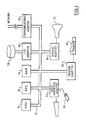
- Figure 1 illustrates a typical hardware configuration of a workstation with a central processing unit 10 (eg. a conventional microprocessor) and a number of other units interconnected via a system bus 12.
- the workstation shown in Figure 1 includes a random access memory RAM 14, a read only store 16, an I/O adapter 18 for connecting peripheral devices such as disk units 20 to the bus, a user interface adapter 22 for connecting a keyboard 24 and/or a mouse 26 and/or other user interface devices (eg. a touch screen controller, not shown) to the bus, a communications adapter 28 for connecting the workstation to a data processing network a display adapter 30 for connecting the bus to a display device 32 (eg. a CRT monitor) and a printer adapter 34 for connecting the bus to a printing device 36.
- a display adapter 30 for connecting the bus to a display device 32 (eg. a CRT monitor)
- printer adapter 34 for connecting the bus to a printing device 36.
- FIG. 1 illustrates only one example of a hardware configuration suitable for implementing the invention.
- the hardware of the workstation can be adapted to perform specific tasks as required.
- a television camera may be connected into the system via the display adapter, or otherwise as appropriate, as an image capture device. No details of such further features are given as they are not crucial to the present invention.
- the invention could equally well be implemented on a mainframe data processing system.
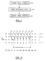
- Figure 2 is a schematic illustrating that image processing logic 40 receives pixel data for an image to be rendered from source image storage 42 and outputs the processed image data to an output image storage 44.
- the source image storage 40 and the output image storage are first and second sets, respectively of locations in the workstation RAM 14.
- the image processing logic 40 is provided by suitable implementing software which is also stored, in use, in the workstation RAM and is used to control the operation of the workstation.
- the input image will have been derived from an image generator and stored in the source storage. How the image is generated is not important here, except to say that it is assumed that the source image contains edges manifesting staircase aliasing.
- the output image storage 44 is a second set of locations in the workstation RAM 14.
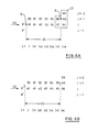
- FIG 3 illustrates a block of pixels forming part of an image.
- Each letter "A”, or “B” represents a pixel, not a displayed character symbol.
- the pixels are assumed to have one of two colours “A” or “B” in Figure 3.
- the image may contain pixels having many more colours and/or intensities.
- the colour "A” relates to a first area and the colour "B” to a second area.
- the transition between the area “A” and the area “B” forms a stepped transition between those areas representing an edge which is neither horizontal nor vertical, but lies at an angle.
- the image has not been anti-aliased as a step-like edge can be clearly seen.
- a staircase point is a point where the transition, or edge, between the areas which is generally angled in a first direction (here the line is approximately horizontal) moves one pixel line in the orthogonal direction (here vertically).
- a staircase point is defined between pixels, not centred on a pixel, in a given pixel row or column.
- FIG 3 there is a staircase point "Q” in the row “J” and a staircase point “R” in the row J+1.
- staircase segment SS
- J the rows or columns
- Figure 4 illustrates logic for analysing the image in the source storage in order to detect edges such as that shown in Figure 3 and to store a modified version of the image in the output storage.
- the effect of the processing is to produce a modified image in which the staircasing effect has been reduced by selective anti-aliasing.
- the image processing logic operates by firstly copying (50) the input image from the input storage (42) to the output storage (44), then completely scanning the image in the input storage four times (S1, S2, S3, S4) and updating the output image on detection of each staircase edge segment.
- Each of the four scans through the input image takes the pixels in a different order and applies a test for a different type of staircase point.
- the image processing logic tests how long the staircase segment is either side of the staircase point in the current line (row or column) of pixels and modifies the output image data depending on the type of staircase segment detected. In this way, by the end of the fourth scan, all staircase segments in the source image are detected and the corresponding data in the output image modified appropriately.
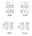
- Figure 5 represents the scan directions for the present example of the invention.
- the first scan (Figure 5A) starts in the bottom left hand corner of the image, and scans each row of the image in turn progressing up the image, with the rows being scanned from left to right.
- the line SP1 over the image array in Figure 5A represents the shape of the transition tested for in the first scan, this shape of transition forms the first type of staircase point and corresponds to the shape of transition at the point Q in Figures 3 and 6.
- the second scan ( Figure 5B) then starts from the bottom right of the image and scans each row in turn progressing up the image with each row being scanned from right to left.
- the line SP2 over the image array in Figure 5B represents the shape of the transition tested for in the second scan, this shape of transition forming the second type of staircase point.
- the third scan starts from the bottom left of the image and scans each column of the image progressing from left to right, with each column being scanned from bottom to top.
- the line SP3 to the left of the image array in Figure 5C represents the shape of the transition tested for in the third scan, this shape of transition forming the third type of staircase point.
- the fourth scan starts from the bottom right of the image and scans each column progressing from right to left across the image with each column being scanned from bottom to top.
- the line SP4 to the left of the image array in Figure 5D represents the shape of the transition tested for in the fourth scan, this shape of transition forming the fourth type of staircase point.
- the logic starts (50) by copying the image from the source (42) to the destination storage (44).
- the image is stored in memory as a two dimensional array of pixels.
- the image will normally be representative of a rectangular array of image pixels, the data defining the pixels may be stored in any appropriate data structure, for example as a series of lists or linked lists as will be apparent to one skilled in the art.
- the image processing logic includes and/or is able to control appropriate addressing logic for accessing the data for pixels at desired row and column locations within the array in a conventional manner.
- the image processing logic starts the first image scan (52, S1) and staircase point detection logic (54) tests successive pixels in turn for a staircase point.
- a staircase point is detected for a row J between a pixel (P(J,I-1)) at column (I-1) and a pixel (P(J,I)) at column (I) when the following condition C1 is satisfied:
- the staircase point detection logic 54 finds no staircase point for a given pixel, and pixels remain for the current scan (64), then the next pixel to be scanned in the scan direction SD is selected and the staircase point detection logic 54 applies the condition C1 for this next pixel.
- first staircase segment logic 56 tests for the length of the staircase segment adjacent to the staircase segment in the scan direction SD. This is done by further scanning along the line of pixels from pixel position I in the scanning direction SD and, at each pixel position, testing whether the following condition C2 is satisfied: where i + 1, 2, 3, .. for successive pixels.
- the first staircase segment logic 56 continues to increment the value of "i" until the condition C2 is no longer satisfied or the end of the current scan line is reached.
- the point where the condition C2 ceases to be satisfied is determined to be the end of a staircase segment (compare point "R", Figure 2).
- the first staircase segment logic 56 passes the number of pixels scanned and the location of the starting and finishing locations of the staircase segment to first image modification logic 58 for modifying the output image storage to remove the staircasing effect.
- the first image modification logic 58 tests to see which case applies and then modifies the data at appropriate locations in the output image.
- FIG. 8A One of the three cases tested for is where the edge between the areas in the image continues in the same general direction as before. An example of this is illustrated in Figure 8A.
- the staircase segment in Figure 8A extends between the staircase points "Q" and "R".
- the first staircase segment logic 58 tests whether the following condition C3 is met for the point at the end of the segment: where k is the number of pixels (in Figure 8A, 6 pixels) stepped in the scanning direction by the logic 56 until the condition C2 ceased to be satisfied.
- the denominators in the above expressions are derived as 2*k (i.e. two times the number of pixels stepped by the logic 56) and the multiplicators for the numerators are determined as a smooth function based on the denominator.
- ai ((k+2i+1)/2k)*Ai + ((k-2i-1)/2k)*Bi
- the result of the above modifications is to set the chrominance and/or luminance values for the modified pixels at particular values between those of the pixels adjacent each side of the transition at that position in the source image. It should be noted that the pixel values for B3, B4 and B5 will be modified by the second image modification logic 62 when this staircase segment SS is detected, during the processing of the next row (J+1), by the second staircase segment logic 60 following detection of the staircase point "R" by the staircase point detection logic 54.
- the second of the three cases tested for is where the edge between the areas in the image turns to form part of an arc.
- An example of this is illustrated in Figure 9A.
- the staircase segment in Figure 9A extends between the staircase points "Q" and "R".
- the first image modification logic 58 tests whether the following condition C4 is met for the point at the end of the segment: where k is once more, the number of pixels (in Figure 9A, 6 pixels) stepped in the scanning direction by the logic 56 until the condition C2 ceased to be satisfied.
- the third case is where neither condition C3, nor condition C4 has been satisfied. This can occur where the edge of the image was encountered during scanning along the staircase segment, where the areas A and B merge into one another, or where another edge breaks in. In this case the edge is assumed to lie on a line (not shown) joining "Q" and "E".
- Figure 10A represents this condition.
- the first image modification logic 58 makes the assumption the end of the segment is midway between the point "Q" and the next staircase point and modifies the pixel data at locations corresponding to all of the points in the current scan line from "Q" to "E".
- the second staircase segment detection logic 60 continues to increment the value of "i" until the condition C5 is no longer satisfied or the beginning of the current scan line is reached. The point where the condition C5 ceases to be satisfied is determined to be the end of a staircase segment. In this case, the second staircase segment detection logic 56 passes the number of pixels scanned and the location of the starting and finishing locations of the staircase segment to second image modification logic 60 for modifying the output image storage to remove the staircasing effect.
- the second image modification logic detects one of three possible cases:
- the second image modification logic 62 detects these cases by testing for conditions comparable to those described with reference to Figures 8A, 8B, 9A, 9B, 10A and 10B, but modified to take account of the opposed scanning direction.
- the conditions used are not described herein but can be readily derived from the conditions C3 and C4 above after comparison of the differences between conditions C2 and C5.
- the modifications performed on the image in the output storage by the second image modification logic 62 in response to the detection of these conditions being met can be derived readily from the description of the equivalent cases for the scanning direction SD.
- the processing is continued for the next pixel to be considered in the scanning direction SD.
- the image processing logic starts 68 the second full scan of the image in the input storage and modifies the image in the output storage by second scan logic S2 corresponding generally to the first scanning logic S1.
- the second scanning logic S2 only differs in so far as to take account of the different scanning order. The details of the second scanning logic are not described as they can be derived readily from what has already been described above.
- the source image storage 40 and the output image storage are first and second sets, respectively of locations in the workstation RAM 14 and the image processing logic 40 is provided by suitable implementing software which is also stored, in use, in the workstation RAM, this need not be the case.
- One or both of the image stores may be provided by special purpose storage, for example, the output storage may be a display buffer used directly for driving a display device.
- the image processing logic may be provided by special purpose hardware.
- the image processing logic may be provided by an array of special purpose processing elements, or by a programmable logic array, or any other suitable hardware means.
- the array may be scanned in different combination of directions and/or in a different order and still detect all the stepped transitions to be anti-aliased.
- the image processing logic scans the image array four times, each time in a different pixel order. In each scan a test is applied to identify a particular type of staircase point. When a staircase point is detected, the length and type of staircase segment to each side of the staircase point are determined and appropriate modifications made to the output image. This approach can be described by the following logical statements:
- the image processing logic could be arranged to examine each pixel position in turn; at each pixel position testing for four different types of staircase point.
- the length and the type of staircase segment to each side of the staircase point are determined and appropriate modifications made to the output image. This approach can be described by the following logical statements:
- the anti-aliasing can be applied equally well to the anti-aliasing of images for display on a visual display device such as a computer monitor and on a printer with multi-level or pseudo-halftone capability.
Landscapes
- Physics & Mathematics (AREA)
- General Physics & Mathematics (AREA)
- Engineering & Computer Science (AREA)
- Theoretical Computer Science (AREA)
- Image Processing (AREA)
- Image Generation (AREA)
- Facsimile Image Signal Circuits (AREA)
- Controls And Circuits For Display Device (AREA)
Priority Applications (4)
| Application Number | Priority Date | Filing Date | Title |
|---|---|---|---|
| EP90302406A EP0445451A1 (fr) | 1990-03-07 | 1990-03-07 | Processeur d'image pour produire des images non-corrompues |
| JP3019226A JPH04218095A (ja) | 1990-03-07 | 1991-01-21 | 画像処理装置およびデータ処理システム |
| CA002037386A CA2037386C (fr) | 1990-03-07 | 1991-03-01 | Processeur d'images |
| US07/895,182 US5301038A (en) | 1990-03-07 | 1992-06-05 | Image processor and method for processing pixel data |
Applications Claiming Priority (1)
| Application Number | Priority Date | Filing Date | Title |
|---|---|---|---|
| EP90302406A EP0445451A1 (fr) | 1990-03-07 | 1990-03-07 | Processeur d'image pour produire des images non-corrompues |
Publications (1)
| Publication Number | Publication Date |
|---|---|
| EP0445451A1 true EP0445451A1 (fr) | 1991-09-11 |
Family
ID=8205318
Family Applications (1)
| Application Number | Title | Priority Date | Filing Date |
|---|---|---|---|
| EP90302406A Withdrawn EP0445451A1 (fr) | 1990-03-07 | 1990-03-07 | Processeur d'image pour produire des images non-corrompues |
Country Status (4)
| Country | Link |
|---|---|
| US (1) | US5301038A (fr) |
| EP (1) | EP0445451A1 (fr) |
| JP (1) | JPH04218095A (fr) |
| CA (1) | CA2037386C (fr) |
Cited By (3)
| Publication number | Priority date | Publication date | Assignee | Title |
|---|---|---|---|---|
| EP0686941A3 (fr) * | 1994-06-07 | 1996-04-24 | Matsushita Electric Industrial Co Ltd | Procédé et appareil de traitement graphique |
| WO2000010326A3 (fr) * | 1998-08-12 | 2000-05-18 | Focus Enhancements Inc | Filtre anti-scintillement reglable en deux dimensions |
| EP0946048A3 (fr) * | 1998-03-23 | 2000-10-04 | Xerox Corporation | Procédé pour le codage des informations de position de contour de haute résolution dans des informations d'image à tonalités continues |
Families Citing this family (22)
| Publication number | Priority date | Publication date | Assignee | Title |
|---|---|---|---|---|
| US5799111A (en) * | 1991-06-14 | 1998-08-25 | D.V.P. Technologies, Ltd. | Apparatus and methods for smoothing images |
| US5442462A (en) * | 1992-06-10 | 1995-08-15 | D.V.P. Technologies Ltd. | Apparatus and method for smoothing images |
| US5778105A (en) * | 1994-01-14 | 1998-07-07 | R.R. Donnelley & Sons Company | Method of and apparatus for removing artifacts from a reproduction |
| US6128000A (en) * | 1997-10-15 | 2000-10-03 | Compaq Computer Corporation | Full-scene antialiasing using improved supersampling techniques |
| US6204859B1 (en) | 1997-10-15 | 2001-03-20 | Digital Equipment Corporation | Method and apparatus for compositing colors of images with memory constraints for storing pixel data |
| US20060250414A1 (en) * | 2005-05-03 | 2006-11-09 | Vladimir Golovin | System and method of anti-aliasing computer images |
| IL172797A (en) * | 2005-12-25 | 2012-09-24 | Elbit Systems Ltd | Real-time image scanning and processing |
| US7826683B2 (en) * | 2006-10-13 | 2010-11-02 | Adobe Systems Incorporated | Directional feathering of image objects |
| US8786625B2 (en) * | 2010-09-30 | 2014-07-22 | Apple Inc. | System and method for processing image data using an image signal processor having back-end processing logic |
| US9025867B2 (en) | 2012-05-31 | 2015-05-05 | Apple Inc. | Systems and methods for YCC image processing |
| US9014504B2 (en) | 2012-05-31 | 2015-04-21 | Apple Inc. | Systems and methods for highlight recovery in an image signal processor |
| US9332239B2 (en) | 2012-05-31 | 2016-05-03 | Apple Inc. | Systems and methods for RGB image processing |
| US8817120B2 (en) | 2012-05-31 | 2014-08-26 | Apple Inc. | Systems and methods for collecting fixed pattern noise statistics of image data |
| US9142012B2 (en) | 2012-05-31 | 2015-09-22 | Apple Inc. | Systems and methods for chroma noise reduction |
| US8872946B2 (en) | 2012-05-31 | 2014-10-28 | Apple Inc. | Systems and methods for raw image processing |
| US9105078B2 (en) | 2012-05-31 | 2015-08-11 | Apple Inc. | Systems and methods for local tone mapping |
| US8953882B2 (en) | 2012-05-31 | 2015-02-10 | Apple Inc. | Systems and methods for determining noise statistics of image data |
| US9031319B2 (en) | 2012-05-31 | 2015-05-12 | Apple Inc. | Systems and methods for luma sharpening |
| US9077943B2 (en) | 2012-05-31 | 2015-07-07 | Apple Inc. | Local image statistics collection |
| US9743057B2 (en) | 2012-05-31 | 2017-08-22 | Apple Inc. | Systems and methods for lens shading correction |
| US11089247B2 (en) | 2012-05-31 | 2021-08-10 | Apple Inc. | Systems and method for reducing fixed pattern noise in image data |
| US8917336B2 (en) | 2012-05-31 | 2014-12-23 | Apple Inc. | Image signal processing involving geometric distortion correction |
Citations (3)
| Publication number | Priority date | Publication date | Assignee | Title |
|---|---|---|---|---|
| US4371872A (en) * | 1979-07-23 | 1983-02-01 | The Singer Company | Fractional clock edge smoother for a real-time simulation of a polygon face object system |
| EP0186828A2 (fr) * | 1984-12-17 | 1986-07-09 | EDELSON, Steven D. | Méthode et dispositif de génération de lignes lisses dans un dispositif d'affichage graphique commandé par ordinateur avec correspondance univoque entre éléments d'image et cellules de mémoire |
| EP0201972A2 (fr) * | 1985-05-13 | 1986-11-20 | Philips Electronics Uk Limited | Méthode et circuit d'arrondissage d'éléments d'image pour un dispositif d'affichage à balayage à trame et dispositif d'affichage à balayage à trame comportant un tel circuit |
Family Cites Families (5)
| Publication number | Priority date | Publication date | Assignee | Title |
|---|---|---|---|---|
| GB2103449B (en) * | 1981-06-29 | 1985-05-30 | Nippon Telegraph & Telephone | Method and apparatus for gray level signal processing |
| US4484349A (en) * | 1982-03-11 | 1984-11-20 | Environmental Research Institute Of Michigan | Parallel pipeline image processor |
| US4486785A (en) * | 1982-09-30 | 1984-12-04 | International Business Machines Corporation | Enhancement of video images by selective introduction of gray-scale pels |
| US4873515A (en) * | 1987-10-16 | 1989-10-10 | Evans & Sutherland Computer Corporation | Computer graphics pixel processing system |
| US4908780A (en) * | 1988-10-14 | 1990-03-13 | Sun Microsystems, Inc. | Anti-aliasing raster operations utilizing sub-pixel crossing information to control pixel shading |
-
1990
- 1990-03-07 EP EP90302406A patent/EP0445451A1/fr not_active Withdrawn
-
1991
- 1991-01-21 JP JP3019226A patent/JPH04218095A/ja active Pending
- 1991-03-01 CA CA002037386A patent/CA2037386C/fr not_active Expired - Fee Related
-
1992
- 1992-06-05 US US07/895,182 patent/US5301038A/en not_active Expired - Fee Related
Patent Citations (3)
| Publication number | Priority date | Publication date | Assignee | Title |
|---|---|---|---|---|
| US4371872A (en) * | 1979-07-23 | 1983-02-01 | The Singer Company | Fractional clock edge smoother for a real-time simulation of a polygon face object system |
| EP0186828A2 (fr) * | 1984-12-17 | 1986-07-09 | EDELSON, Steven D. | Méthode et dispositif de génération de lignes lisses dans un dispositif d'affichage graphique commandé par ordinateur avec correspondance univoque entre éléments d'image et cellules de mémoire |
| EP0201972A2 (fr) * | 1985-05-13 | 1986-11-20 | Philips Electronics Uk Limited | Méthode et circuit d'arrondissage d'éléments d'image pour un dispositif d'affichage à balayage à trame et dispositif d'affichage à balayage à trame comportant un tel circuit |
Cited By (3)
| Publication number | Priority date | Publication date | Assignee | Title |
|---|---|---|---|---|
| EP0686941A3 (fr) * | 1994-06-07 | 1996-04-24 | Matsushita Electric Industrial Co Ltd | Procédé et appareil de traitement graphique |
| EP0946048A3 (fr) * | 1998-03-23 | 2000-10-04 | Xerox Corporation | Procédé pour le codage des informations de position de contour de haute résolution dans des informations d'image à tonalités continues |
| WO2000010326A3 (fr) * | 1998-08-12 | 2000-05-18 | Focus Enhancements Inc | Filtre anti-scintillement reglable en deux dimensions |
Also Published As
| Publication number | Publication date |
|---|---|
| CA2037386C (fr) | 1995-08-15 |
| US5301038A (en) | 1994-04-05 |
| JPH04218095A (ja) | 1992-08-07 |
Similar Documents
| Publication | Publication Date | Title |
|---|---|---|
| CA2037386C (fr) | Processeur d'images | |
| US6720975B1 (en) | Super-sampling and multi-sampling system and method for antialiasing | |
| DE69602728T2 (de) | Vorrichtung zur bildmanipulation und -generation | |
| US6868189B1 (en) | Image processing apparatus, an image processing method, and a computer readable medium having recorded thereon a processing program for permitting a computer to perform image processing routines | |
| US6894701B2 (en) | Type size dependent anti-aliasing in sub-pixel precision rendering systems | |
| US6768491B2 (en) | Barycentric centroid sampling method and apparatus | |
| US20050179698A1 (en) | Selective super-sampling/adaptive anti-aliasing of complex 3D data | |
| US6292192B1 (en) | System and method for the direct rendering of curve bounded objects | |
| GB2561557A (en) | Method of and apparatus for processing graphics | |
| EP1295256B1 (fr) | Procede et systeme reduisant les surdebits dans un systeme graphique informatique | |
| JP2005122361A (ja) | 画像処理装置及び方法、コンピュータプログラム、記録媒体 | |
| EP0601116B1 (fr) | Appareil permettant de generer un halo d'image d'affichage anti-replie | |
| JPH0322188A (ja) | 図形イメージをラスタ化して表現する方法 | |
| US5175805A (en) | Method and apparatus for sequencing composite operations of pixels | |
| US6377273B1 (en) | Fast area-coverage computing method for anti-aliasing in graphics | |
| JP3174342B2 (ja) | 多値レベルから2値レベルへのラスタ形状コンバータ | |
| EP1058912B1 (fr) | Anticrenelage des contours de textures sous-echantillonnees | |
| EP0855682B1 (fr) | Rendu de convolutions en lignes de balayage | |
| US7450121B2 (en) | Dynamic bit depth rendering | |
| EP0127249B1 (fr) | Dispositif pour le traitement de données de modèle | |
| US6718072B1 (en) | Image conversion method, image processing apparatus, and image display apparatus | |
| US5898440A (en) | Method of and apparatus for processing graphics data | |
| US20030189575A1 (en) | System and method for improved pixel rendering performance | |
| US6445392B1 (en) | Method and apparatus for simplified anti-aliasing in a video graphics system | |
| Stasik et al. | Improvements in upscaling of pixel art |
Legal Events
| Date | Code | Title | Description |
|---|---|---|---|
| PUAI | Public reference made under article 153(3) epc to a published international application that has entered the european phase |
Free format text: ORIGINAL CODE: 0009012 |
|
| AK | Designated contracting states |
Kind code of ref document: A1 Designated state(s): DE FR GB IT |
|
| 17P | Request for examination filed |
Effective date: 19911219 |
|
| 17Q | First examination report despatched |
Effective date: 19950310 |
|
| STAA | Information on the status of an ep patent application or granted ep patent |
Free format text: STATUS: THE APPLICATION IS DEEMED TO BE WITHDRAWN |
|
| 18D | Application deemed to be withdrawn |
Effective date: 19951121 |