EP0445462A1 - Commande d'entrée d'air électrique - Google Patents
Commande d'entrée d'air électrique Download PDFInfo
- Publication number
- EP0445462A1 EP0445462A1 EP90311463A EP90311463A EP0445462A1 EP 0445462 A1 EP0445462 A1 EP 0445462A1 EP 90311463 A EP90311463 A EP 90311463A EP 90311463 A EP90311463 A EP 90311463A EP 0445462 A1 EP0445462 A1 EP 0445462A1
- Authority
- EP
- European Patent Office
- Prior art keywords
- pressure
- vacuum
- timer
- control valve
- air
- Prior art date
- Legal status (The legal status is an assumption and is not a legal conclusion. Google has not performed a legal analysis and makes no representation as to the accuracy of the status listed.)
- Ceased
Links
- 239000010865 sewage Substances 0.000 claims abstract description 80
- 239000002699 waste material Substances 0.000 claims description 19
- 238000004891 communication Methods 0.000 claims description 17
- 238000000034 method Methods 0.000 claims description 11
- 230000004913 activation Effects 0.000 claims description 8
- 230000004044 response Effects 0.000 claims description 7
- 230000005611 electricity Effects 0.000 claims description 2
- 230000003213 activating effect Effects 0.000 claims 7
- 230000001105 regulatory effect Effects 0.000 claims 4
- 238000012544 monitoring process Methods 0.000 claims 1
- 101100500467 Arabidopsis thaliana EAAC gene Proteins 0.000 abstract description 28
- 230000001351 cycling effect Effects 0.000 abstract description 7
- 238000011144 upstream manufacturing Methods 0.000 abstract description 6
- 239000012530 fluid Substances 0.000 abstract description 3
- 230000006870 function Effects 0.000 description 10
- 230000002950 deficient Effects 0.000 description 6
- 230000008569 process Effects 0.000 description 5
- 230000005484 gravity Effects 0.000 description 4
- 239000007788 liquid Substances 0.000 description 4
- 238000010276 construction Methods 0.000 description 2
- 238000010586 diagram Methods 0.000 description 2
- 238000009434 installation Methods 0.000 description 2
- 230000003993 interaction Effects 0.000 description 2
- 238000005259 measurement Methods 0.000 description 2
- 238000012986 modification Methods 0.000 description 2
- 230000004048 modification Effects 0.000 description 2
- 238000010926 purge Methods 0.000 description 2
- 238000009825 accumulation Methods 0.000 description 1
- 230000009471 action Effects 0.000 description 1
- 230000004931 aggregating effect Effects 0.000 description 1
- 230000015572 biosynthetic process Effects 0.000 description 1
- 230000008859 change Effects 0.000 description 1
- 230000009849 deactivation Effects 0.000 description 1
- 238000013461 design Methods 0.000 description 1
- 230000000694 effects Effects 0.000 description 1
- 238000012423 maintenance Methods 0.000 description 1
- 230000007257 malfunction Effects 0.000 description 1
- QSHDDOUJBYECFT-UHFFFAOYSA-N mercury Chemical compound [Hg] QSHDDOUJBYECFT-UHFFFAOYSA-N 0.000 description 1
- 229910052753 mercury Inorganic materials 0.000 description 1
- 238000012545 processing Methods 0.000 description 1
- 230000009467 reduction Effects 0.000 description 1
- 239000011435 rock Substances 0.000 description 1
- 238000007789 sealing Methods 0.000 description 1
- 238000012876 topography Methods 0.000 description 1
- 230000001960 triggered effect Effects 0.000 description 1
- XLYOFNOQVPJJNP-UHFFFAOYSA-N water Substances O XLYOFNOQVPJJNP-UHFFFAOYSA-N 0.000 description 1
Images




Classifications
-
- E—FIXED CONSTRUCTIONS
- E03—WATER SUPPLY; SEWERAGE
- E03F—SEWERS; CESSPOOLS
- E03F1/00—Methods, systems, or installations for draining-off sewage or storm water
- E03F1/006—Pneumatic sewage disposal systems; accessories specially adapted therefore
- E03F1/007—Pneumatic sewage disposal systems; accessories specially adapted therefore for public or main systems
-
- G—PHYSICS
- G01—MEASURING; TESTING
- G01F—MEASURING VOLUME, VOLUME FLOW, MASS FLOW OR LIQUID LEVEL; METERING BY VOLUME
- G01F23/00—Indicating or measuring liquid level or level of fluent solid material, e.g. indicating in terms of volume or indicating by means of an alarm
- G01F23/14—Indicating or measuring liquid level or level of fluent solid material, e.g. indicating in terms of volume or indicating by means of an alarm by measurement of pressure
- G01F23/18—Indicating, recording or alarm devices actuated electrically
- G01F23/185—Indicating, recording or alarm devices actuated electrically for discrete levels
Definitions
- the present invention relates generally to vacuum-operated sewage control systems utilizing inlet vacuum valves, and more specifically to such a system employing an electric air admission controller (“EAAC”) for opening the vacuum valve independently of the level of sewage accumulated in a holding tank at the inlet of the valve, in order to introduce additional air at atmospheric pressure into the sewage transport conduit to avoid a waterlogged state.
- EAAC electric air admission controller
- each sewage inlet point typically serving one or more houses, include a vacuum valve and controller assembly, which allows intermittent passage of accumulated sewage into an associated transportation conduit network connected at the other end to a collection tank, and thereafter ultimately to a sewage treatment plant.
- this conduit is typically laid with a saw-toothed profile with a combination of a riser, low point, and downslope (collectively called a "lift") repeated throughout the length of the sewer main to accommodate the topography (e.g., other conduits and rock layers) as well as incoming flows (from an individual vacuum valve or a branch main).
- the slope of the downslope portions of the profile is such that the drop between lifts is generally equivalent to at least 40% of the conduit diameter (80% if the diameter is smaller than 6") or 0.2% of the distance between lifts, whichever is greater.
- the transport conduit network is continuously maintained under vacuum or subatmospheric pressure. Sewage and air, usually at atmospheric pressure, are introduced for transport into the conduit through an open vacuum valve. The air moves down the length of the conduit to the area under vacuum or subatmospheric pressure where the air expands volumetrically. The energy created by the rapid movement of air in response to the differential pressure condition in the conduit in turn produces rapid sewage transport throughout the conduit system.
- the vacuum valve will close, thereby ending the sewage transport cycle.
- the expansion of air causes a reduction in its pressure and velocity, and any residual waste not transported through the conduit network during the sewage transport cycle comes to rest.
- the conduit downstream of the vacuum valve is equalized by the source of vacuum pressure to a substantially constant subatmospheric or vacuum pressure condition throughout. Any residual waste not transported through the conduit during the sewage transport cycle will generally come to rest in the low point portion, permitting vacuum or subatmospheric pressure to be communicated and maintained throughout the entire conduit section.
- Vacuum valves function within this system by sealing and unsealing the passage between two parts of an evacuated system to define a transport cycle.
- the general structure and method of operation of this type of vacuum valve is described in U.S. Pat. No. 4,171,853, issued to D. D. Cleaver et al.
- a problem encountered by vacuum transport sewage systems is "waterlogging."
- the collection of residual waste material in the low point portions of the conduit under normal operating conditions, is insufficient to seal the conduit at low points, and is designed to maintain throughout the conduit an air space in the conduit to permit pressure communication.
- the total conduit volume will typically be less than one-third liquid.
- an insufficient amount of atmospheric air is introduced into the conduit, there will be insufficient energy applied to move effectively the entire waste mass during the sewage transport cycle. This leads to an increased accumulation of residual waste material creating the waterlogged condition might fill two-thirds of the conduit and lift volumes.
- valve assembly may be misadjusted so that the valve closes too quickly after the waste material has entered the conduit, thereby undesirably reducing the amount of atmospheric air entering the conduit and pulling the waste material along.
- leakage somewhere in the system will impair the maintenance of vacuum or subatmospheric pressure in the conduit so that over time, this vacuum or subatmospheric pressure condition will decrease to the point that the differential pressure during transport cycles will be insufficient to move waste product, resulting in waterlogging.
- conduit network will equalize to a vacuum or subatmospheric pressure after the valve closes terminating the sewage transport cycle, it will do so at a slightly lower vacuum pressure due to inefficiency in the system or improper operation of the source of vacuum or subatmospheric pressure. This, in turn, contributes to a deficient level of vacuum or subatmospheric pressure and therefore, pressure differential.
- each saw-toothed lift consists of a lower downslope portion, a riser, and an upper downslope portion
- the pertinent distance is measured vertically between the point on the bottom exterior surface of the upper downslope portion where it joins the riser, and the point on the top exterior surface of the lower downslope portion where it joins the riser. Aggregating these distances across the lifts of the flow path produces a measurement for the "total lift.”
- a vacuum system operates within a range of 16" Hg to 20" Hg vacuum. Because atmospheric pressure, on the other hand, is defined as O" Hg in this vacuum pressure scale, this represents “a pressure differential" of 16" Hg to 20" Hg also. Taking the minimum available vacuum level of 16" Hg, and subtracting 5" Hg which must be present at all times to operate the vacuum valves and their controls leaves 11" Hg vacuum available for vacuum lift in the mains. Eleven inches of mercury is equivalent to 12.5 feet of water, which is typically rounded up to 13 feet. Thus, 13 feet of lift is typically the maximum figure used in the design of the vacuum mains for any sewer project.
- Total lift of approximately 13 feet is important for two reasons. First, any system with less than 13 feet of lift which waterlogs can theoretically correct itself over time through normal valve cycling to purge the accumulated residual sewage from the conduit line. By contrast, a waterlogged vacuum transport system designed with 13 feet or more of total lift traditionally has needed operator assistance to purge the residual sewage. Because the valve opens in response to differential pressure based upon the vacuum pressure condition in the conduit immediately downstream of the valve, if that vacuum pressure is too low due to waterlogging blockage of the conduit, the valve will not cycle to introduce atmospheric pressure into the conduit, thereby preventing the conduit from automatically unwaterlogging itself over time.
- the repairman will have to restore the source of vacuum pressure in the system, move upstream to a valve having adequate vacuum pressure able to be activated and activate that valve, and then progressively activate each valve further upstream until the vacuum mains are cleared of the waterlogged sewage.
- the second important aspect of the 13-foot measurement is that it presents a limitation on the overall length of the sewage transport lines. Combination of the predetermined slope of the lines with a maximum total lift of 13 feet determines the maximum distance the vacuum lines may travel to ensure proper sewage flow without the aid of mechanical pumps. Actually, the total permitted lift across the flow path is limited additionally by a frictional loss factor calculated according to various formulae known in the art of fluid dynamics.
- a higher air-to-liquid ratio is used. This may be simply accomplished by admitting more air into the conduit.
- Typical systems operating at or below the 13-foot level may be designed at a 3-to-1 air-to-liquid ratio. This number can be proportionately increased to increase lift within the system.
- Another object of the present invention is to provide an apparatus which will act to open and close a vacuum valve to admit additional air to a vacuum main to avoid the vacuum main becoming waterlogged, independent of the normal activation of the vacuum valve to admit accumulated waste matter from a holding tank into the vacuum main.
- Yet another object of the present invention is to allow the construction of vacuum sewage pipe networks with total lift exceeding 13 feet.
- the invention is directed to providing an EAAC apparatus and a method for automatically opening and closing an air control valve connected to a vacuum sewage transport conduit with a sewage control valve, independently of the level of accumulated sewage upstream of the sewage control valve, in order to inject additional air at atmospheric pressure into the vacuum transport lines to apply additional fluid pressure to a mass of sewage therein, and to avoid a waterlogged condition by supplementary transport.
- the apparatus comprises a solenoid valve and a timer-unit.
- the timer unit When the timer unit is activated, it in turn activates the solenoid valve which responds by delivering vacuum or subatmospheric pressure from an external source to the air control valve to open it by application of differential pressure.
- the on-timer cycle is completed, atmospheric pressure is once again delivered to the air control valve to close the valve.
- the predetermined frequency and duration of timer activation is calculated to permit sufficient atmospheric air to be introduced into the transport conduit to, on average, prevent waterlogging.
- a pressure switch and timer-delay module are added to the EAAC system.
- the pressure switch monitors the level of vacuum pressure differential in the transport conduit downstream of the control valve. When the vacuum pressure falls to or below a pre-determined level, e.g., 12" Hg, the pressure switch activates the timer-delay component. When the timer-delay cycle is completed, if the level of vacuum pressure differential in the conduit line is still deficient, then the timer component is activated. This component in turn activates the solenoid valve.
- timer-delay component is activated again, and the pressure switch remonitors the level of vacuum pressure in the transport conduit when the timer-delay cycle is completed.
- the timer and timer-delay components or modules have control knobs for adjusting the duration of their respective activation cycles.
- the EAAC is combined in tandem with the sensor-controller module, which normally cycles the sewage vacuum control valve when a certain predetermined level of sewage is accumulated in a holding tank upstream of the sewage control valve.
- the solenoid valve when activated, responds by delivering atmospheric pressure from an external source to the sensor-controller module. This, in turn, acts to open the sewage control valve by application of differential pressure.
- vacuum pressure is once again delivered to the sensor-controller module, which reverses the differential pressure process and, in turn, responds by closing the sewage control valve.
- the special air control valves are unnecessary.
- the vacuum sewage transport system 10 includes a gravity sever conduit 11 at atmospheric pressure which drains from a point of sewage inside a dwelling.
- the gravity sewer conduit 11 is arranged to convey sewage to a holding tank 12, which is also ordinarily maintained essentially at atmospheric pressure.
- a sensor pipe 13 is supported at the top of the holding tank 12 and extends downwardly to a point inside the tank. The sensor pipe 13 extends from its top support upwards into a valve pit 16 into which the sensor pipe 13 opens.
- sewage is discharged from a residential source into the gravity sewer conduit 11, which in turn discharges the sewage into holding tank 12.
- the control valve 20 is opened by the sensor control apparatus 25, which will be described more fully below, and triggers a normal sewage transport cycle. Opening the control valve 20 creates a differential pressure between the relatively low pressure or vacuum portion of the discharge conduit 15 downstream from the valve, and the higher or atmospheric pressure portion of conduit 15 upstream of valve 20.
- control valve 20 Upon the upper end 21 of control valve 20 is mounted an integrated sensor-controller module 25.
- the control module is attached by means of bracket 26 and screws 27 (best seen in Fig. 5).
- One of the ends of a pressure sensor conduit 28 is disposed in pressure communication with the sensor pipe 13, and its other end is coupled to pressure sensor port 31, positioned at the lowest point of the sensor-controller module 25.
- Vacuum is supplied to the sensor-controller through a vacuum line 34 connected through a surge tank 37, which is more fully described in applicant's U.S. Pat. No. 4,171,853.
- the surge tank communicates with the vacuum portion of discharge conduit 15, thereby supplying a constant subatmospheric or vacuum pressure source to the sensor-controller through vacuum line 34 and vacuum port 30.
- Atmospheric pressure is directed to the sensor-controller 25 from above the ground surface of the installation through an air breather 33, which communicates with an atmospheric pressure conduit 36, thereby supplying atmospheric pressure to the sensor-controller through atmospheric port 39 (as seen in Fig. 5).
- atmospheric pressure is delivered to the lower housing chamber of the pressure differentially operated valve 20 from atmospheric pressure conduit 36 via atmospheric pressure conduit 32, which joins the former at junction point 35.
- the sensor-controller 25 communicates with the pressure differentially operated valve 20 via a valve connector 42 disposed in pressure communication with the upper end 21 of valve 20 and valve connector port 45 of module 25 (see Fig. 5).
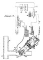
- the EAAC module 17 is designed to open the control valve 20 to admit atmospheric air during an air transport cycle of predetermined length in order to prevent the onslaught of, or correct the existence of, a waterlogged condition in the sewage transport conduit 15.
- the simplest manner to achieve this objective is to join one or more air valves 46 coupled to an EAAC module 17 at strategic locations in the conduit line 15 by means of a connecting conduit 48, as shown in Fig. 2.
- These air valves 46 are independent of the sewage control valves 20 positioned immediately downstream of each sewage holding tank 12 (as shown in Fig. 1) but have the same mechanical structure, and operate in the same manner.
- air valve 46 has a wye-body conduit 50 with a valve housing 51 and an internal valve seat 53. Mounted to valve housing 51 are a lower housing chamber 55 and an upper housing chamber 57, divided by diaphragm 60. One end of plunger assembly 62 mates with internal valve seat 53 in order to provide an air and water-tight seal. Plunger assembly 62 is attached to piston rod 65 and can move longitudinally within valve housing 51. The other end of piston rod 65 is attached to piston-cup 67. Spring 70 is positioned between piston-cup 67 and the top side 21 of upper housing chamber 57 in order to bias plunger assembly 62 tightly in contact with internal valve seat 53.
- the upper housing chamber 57 is at atmospheric pressure. Meanwhile, air at atmospheric pressure enters wye-body conduit 50 to fill valve housing 51 and lower housing chamber 55 at all times.
- the atmospheric pressure in lower housing chamber 55 deflects diaphragm 60 upwards toward the top side 21 of upper housing chamber 57. This action, in turn, moves piston cup 67 against spring 70 and with it piston rod 65 so that plunger assembly 62 moves away from internal valve seat 53. In this way the valve "opens.”
- the key to opening air control valve 46 is to introduce vacuum or subatmospheric pressure into upper housing chamber 57.
- Fig. 2 also shows a schematic diagram of EAAC module 17 in its simplest form.
- a 3-way, 2-position, spring-return electric actuated valve (“solenoid valve”) 80 is used to deliver air at a selected pressure condition to valve connector 42 and upper housing chamber 57 of air valve 46 by means of pressure delivery line 82.
- solenoid valve 80 receives air at atmospheric pressure by means of atmospheric pressure source 84, and vacuum or subatmospheric pressure by means of vacuum line 86.
- the source 87 of the vacuum or subatmospheric pressure could be either a vacuum pump or else the vacuum or subatmospheric pressure within conduit line 15, itself.
- solenoid valve 80 In response to electrical current provided by power source 90, a magnetic coil in the solenoid valve 80 will cause, by means of interaction of the mechanical parts, vacuum or subatmospheric pressure to be passed to upper housing chamber 57, and the air valve 46 opens. Termination of flow of electrical current to solenoid valve 80, by contrast, will cause atmospheric pressure to be delivered to the upper housing chamber 57, thereby closing the air valve 46.
- a timer module 100 is interposed within the electrical circuit between power source 90 and solenoid valve 80.
- Typical timers used include those sold by National Controls Corporation of West Chicago, Illinois. Such a timer provides an electrical flow path which is interrupted for a pre-determined period of time. The timer may have means for adjusting this period of deactivation.
- solenoid valve 80 will receive electrical current only when the timer module 100 is activated to complete the electrical circuit. In this way, air valve 46 will cycle to provide intermittent introduction of air at atmospheric pressure in conduit line 15 to prevent waterlogging.
- FIG. 3 A preferred embodiment of the present invention is shown in Fig. 3. Rather than adjust the timer module's activation period to produce an air transport cycle for the air valve 46 sufficiently long, on average, to prevent the differential pressure in the conduit line from falling to or below a predetermined level, such as 12" Hg, a pressure-activated, double-pull, single-throw electric switch ("pressure switch") 110 is placed in the electrical circuit of EAAC module 17 between power source 90 and on-timer module 100.
- a typical pressure switch used is the combination of Switch Unit No. PB30A and Transducer Unit No. RV34A32, both sold by Automatic Switch Co. of Florham Park, New Jersey.
- Vacuum line 112 supplies to pressure switch 110 a steady stream of vacuum/subatmospheric pressurized air from a point in conduit 48 which joins air valve 46 and conduit line 15.
- a surge tank 114 may be interposed within vacuum line 112 to prevent any waste liquids that might have flown into conduit 48 from migrating into pressure switch 110.
- Pressure switch 110 is activated, and therefore allows electric current to flow from power source 90 to the timer module, when the vacuum pressure condition delivered to it falls to or below 12" Hg.
- a delay-timer module 105 is interposed within the electrical circuit of EAAC module 17 between pressure switch 110 and on-timer module 100.
- Delay-timer module 105 and on-timer module 100 are combined in time delay relay modules such as Model CKK sold by National Controls Corporation of West Chicago, Illinois.
- Delay-timer module 105 ameliorates the problem of perpetual cycling of air valve 46 by turning to the "off" position when voltage is delivered to it, thereby commencing a delay cycle.
- the delay-timer module 105 changes to the "on" position and delivers voltage to on-timer module 100.
- on-timer module 100 will convert to the "on" position (commencing as timer cycle) and deliver current to solenoid valve 80, which thereby causes vacuum/subatmospheric pressure to be delivered to upper housing chamber 57 of air valve 46, and air valve 46 opens to admit atmospheric pressure to conduit line 15.
- on-timer module 100 At the end of the predetermined timer cycle of on-timer module 100, it will convert to the "off" position, to deactivate solenoid valve 80, and the process will reverse to close air valve 46. Meanwhile, delay-timer module 105 will activate once again to provide a delay period to allow vacuum/subatmospheric pressure to be restored to conduit 48 immediately downstream of air valve 46. Both delay-timer module 105 and on-timer module 100 may have control knobs which permit the time of activation of each unit to be independently adjusted.
- pressure switch 110 may be adjusted to monitor other pre-selected levels of differential pressure.
- power source 90 delivers electrical current at 110 volts.
- this requires the installation of an electrical power wire in the valve pit to make such an amount of voltage available to operate the EAAC unit. Therefore, the components in the EAAC unit may be replaced with corresponding ones which perform similar functions, but operate on 12 volts, so that a simple 12 volt battery can be placed in the valve pit to operate the EAAC unit.
- Fig. 4 illustrates the interrelation of the various components of EAAC module 17 and air valve 46 in terms of function v. time.
- the pressure differential in conduit line 15 is sufficient, atmospheric pressure is delivered to air valve 46 to keep it closed, and pressure switch 110, delay-timer module 105 and on-timer module 100 are all deactivated ("off").
- the pressure differential condition becomes deficient, pressure switch 110 is activated and timer-delay 105 module is activated to commence the delay cycle.
- delay-timer module 105 deactivates, the pressure condition is still deficient, and on-timer module 100 activates to activate solenoid valve 80. Meanwhile, vacuum/subatmospheric pressure is delivered to air valve 46 to open it.
- the on-timer module 100 deactivates as does the solenoid valve 80, and atmospheric pressure is once again delivered to air valve 46 to close it.
- delay-timer module 105 is once again activated.
- the delay cycle ends at time t5 at which point the pressure condition in conduit line 15 is sufficient to avoid waterlogging.
- the pressure differential is deficient, and the process begins once again.
- Fig. 5 shows yet another preferred embodiment of the invention.
- a unit controller module 25 regulates the cycling of waste control valve 20.
- Applicant's U.S. Pat. No. 4,373,838 discloses in great detail the structure and operation of the unit-controller module.
- the module has air-tight chambers 120, 122, 124, 126, 128, and 130.
- Vacuum line 34, surge tank 37, and vacuum port 30 ensure that chamber 128 is always maintained at the vacuum/subatmospheric pressure condition in conduit line 15 immediately downstream of control valve 20.
- Air breather 33, atmospheric pressure conduit 36, atmospheric port 39, and conduit 132 ensure that chambers 130 and 122 are always at atmospheric pressure.
- connecting tube 134 brings chambers 124 and 126 to the same vacuum/atmospheric pressure condition which exists in chamber 128.
- sensor pipe 13, pressure sensor conduit 28, and pressure sensor port 31 conveys the pressure condition in holding tank 12 (which increases as the level of sewage increases) to chamber 120.
- valve connector port 45 and valve connector 42 deliver atmospheric pressure to the upper housing chamber 57 of waste control valve 20.
- pressure communication between the various chambers shuts off delivery of atmospheric pressure from atmospheric port 39 to valve connector 42, and instead vacuum/subatmospheric pressure is delivered from chamber 128 to chamber 130, valve connector 42, and hence upper housing chamber 57 to cause opening of the waste control valve 20. Reversal of this process causes closure of the valve.
- the unit-controller module 25 opens and closes the valve by delivering vacuum/subatmospheric and atmospheric pressurized air, respectively.
- the invention embodied in Fig. 5 connects the EAAC module 17 to the unit-controller module 25, instead of directly to the valve as embodied by the inventions shown in Figs. 2 and 3.
- This promotes efficiency and reduces costs because it eliminates the need for special air control valve 46 to admit atmospheric air into conduit line 15.
- Sewage control valve 20 must already be used to admit sewage into the conduit transport lines, so this valve serves a second function by also allowing entry of atmospheric air when needed to avoid waterlogging in the conduit line 15.
- the EAAC module 17 is constructed and operated in the same way as when the EAAC module is connected directly to the valve with one important exception: the atmospheric and vacuum/subatmospheric pressure delivery lines 84 and 86, respectively, connected to solenoid valve 80 are reversed. In this way, compared with each respective position of two-way position solenoid valve 80 in Figs. 2 and 3, the pressure characteristic of air exiting the solenoid valve and delivered to chamber 124 of the unit-controller module 25 in Fig. 5 will be reversed.
- the timer cycle of on-timer unit 100 will determine the duration of the air transport cycle of waste control valve 20 while it is being activated by EAAC module 17, and therefore how much air at atmospheric pressure can enter conduit line 15 to prevent or cure any waterlogging.
- delay-timer module 105 and on-timer module 100 may be equipped with control knobs to vary the length of their activation cycles. This will determine not only the length of the air transport cycle of waste control valve 20, but also the duration of delay caused by timer delay module 105 both before and after control valve 20 cycles to ensure that the inadequate pressure differential in conduit line 15 monitored by pressure switch 110 is not unduly transitory.
- Fig. 6 shows the invention, as embodied in Fig. 5, in terms of the various component functions versus time. Comparison of Fig. 6 with Fig. 4 will show the primary differences functionally between the inventions of Fig. 5 and Fig. 3.
Landscapes
- Health & Medical Sciences (AREA)
- Life Sciences & Earth Sciences (AREA)
- Engineering & Computer Science (AREA)
- Hydrology & Water Resources (AREA)
- Public Health (AREA)
- Water Supply & Treatment (AREA)
- Sewage (AREA)
- Control Of Fluid Pressure (AREA)
Applications Claiming Priority (2)
| Application Number | Priority Date | Filing Date | Title |
|---|---|---|---|
| US491255 | 1990-03-09 | ||
| US07/491,255 US5044836A (en) | 1990-03-09 | 1990-03-09 | Electric air admission controller |
Publications (1)
| Publication Number | Publication Date |
|---|---|
| EP0445462A1 true EP0445462A1 (fr) | 1991-09-11 |
Family
ID=23951411
Family Applications (1)
| Application Number | Title | Priority Date | Filing Date |
|---|---|---|---|
| EP90311463A Ceased EP0445462A1 (fr) | 1990-03-09 | 1990-10-18 | Commande d'entrée d'air électrique |
Country Status (5)
| Country | Link |
|---|---|
| US (1) | US5044836A (fr) |
| EP (1) | EP0445462A1 (fr) |
| JP (1) | JP2879992B2 (fr) |
| AU (1) | AU631249B2 (fr) |
| CA (1) | CA2028587A1 (fr) |
Cited By (5)
| Publication number | Priority date | Publication date | Assignee | Title |
|---|---|---|---|---|
| EP0544261A1 (fr) * | 1991-11-27 | 1993-06-02 | Ebara Corporation | Clapet d'interface à vide |
| EP0550980A1 (fr) * | 1992-01-07 | 1993-07-14 | Inax Corporation | Clapet à vide pour système de récupération d'égouts |
| EP0570739A1 (fr) * | 1992-05-20 | 1993-11-24 | Harald Michael | Système de drainage |
| WO2001053733A1 (fr) * | 2000-01-21 | 2001-07-26 | Evac International Oy | Clapet de non-retour pour une vanne electromagnetique commandee indirectement |
| WO2015187228A1 (fr) * | 2014-06-02 | 2015-12-10 | Bilfinger Water Technologies, Inc. | Dispositif de commande pour un système d'égout sous vide |
Families Citing this family (12)
| Publication number | Priority date | Publication date | Assignee | Title |
|---|---|---|---|---|
| WO2008013951A2 (fr) * | 2006-07-27 | 2008-01-31 | Mac Equipment, Inc. | Appareil à soupape de commande d'air de modulation sous vide |
| CN102428235B (zh) * | 2009-04-03 | 2013-10-23 | 株式会社酉岛制作所 | 真空阀的控制装置 |
| US9828757B2 (en) * | 2010-01-27 | 2017-11-28 | Ip Sensing, Inc. | Distributed control system for a vacuum sewer system |
| JP6184714B2 (ja) * | 2013-03-26 | 2017-08-23 | 株式会社荏原製作所 | 真空圧回復装置、真空式下水道システム、真空圧回復方法 |
| US10316504B2 (en) | 2015-08-05 | 2019-06-11 | Aqseptence Group, Inc. | Vacuum sewage system with monitoring system and method of use |
| US10584473B2 (en) | 2017-12-08 | 2020-03-10 | Legend Energy Advisors | Controlling a vacuum sewer system |
| US11299878B2 (en) * | 2019-03-21 | 2022-04-12 | Aqseptence Group, Inc. | Vacuum sewage system with sump breather apparatus |
| US11939760B2 (en) | 2020-03-30 | 2024-03-26 | Aqseptence Group, Inc. | Vacuum sewage system with monitoring system and variable speed pump and methods of use |
| WO2021242627A2 (fr) * | 2020-05-28 | 2021-12-02 | Legend Energy Advisors LLC | Détection de pression négative et de cycle anormal dans un système d'égout sous vide |
| US20220235873A1 (en) * | 2021-01-26 | 2022-07-28 | Aqseptence Group, Inc. | Vacuum sewage systems with check valves and check valves for vacuum sewage systems |
| EP4382685A1 (fr) * | 2022-12-05 | 2024-06-12 | B/E Aerospace, Inc. | Soupape de chasse d'eau à membrane actionnée électropneumatique et électromécanique pour toilettes d'aéronef |
| US12258746B2 (en) | 2022-12-05 | 2025-03-25 | B/E Aerospace, Inc. | Electro pneumatic and electromechanical actuated diaphragm type flush valve for aircraft toilet |
Citations (6)
| Publication number | Priority date | Publication date | Assignee | Title |
|---|---|---|---|---|
| US3777778A (en) * | 1972-08-30 | 1973-12-11 | Johnson Service Co | Two-position liquid level controller |
| DE3011502A1 (de) * | 1979-03-26 | 1980-10-30 | Johnson Controls Inc | Stroemungssteuersystem |
| US4373838A (en) * | 1981-02-13 | 1983-02-15 | Burton Mechanical Contractors Inc. | Vacuum sewage transport system |
| EP0152386A2 (fr) * | 1984-02-10 | 1985-08-21 | Oy Wärtsilä Ab | Dispositif pour système de transport sous vide de liquides, particulièrement système d'égout sous vide |
| EP0170096A2 (fr) * | 1984-08-03 | 1986-02-05 | Bradley Corporation | Mécanisme de rappel commandé à distance pour un système opérant sous vide |
| EP0328457A1 (fr) * | 1988-02-08 | 1989-08-16 | Tectra Societe A Responsabilite Limitee | Procédé d'assainissement sous vide, système d'assainissement sous vide et contrôleur temporisateur destiné à ce système |
Family Cites Families (6)
| Publication number | Priority date | Publication date | Assignee | Title |
|---|---|---|---|---|
| US1964167A (en) * | 1931-02-16 | 1934-06-26 | Gen Conveyors Ltd | Pneumatic dispatch tube apparatus |
| US3814542A (en) * | 1972-06-30 | 1974-06-04 | Sun Oil Co | Automatic pump shutdown circuit |
| US4171853A (en) * | 1977-07-15 | 1979-10-23 | Burton Mechanical Contractors | Vacuum operated sewerage system |
| US4179371A (en) * | 1978-03-20 | 1979-12-18 | Burton Mechanical Contractors, Inc. | Vacuum sewage system |
| DE2833364A1 (de) * | 1978-07-29 | 1980-02-07 | Peters Ag Claudius | Saugkopf fuer eine pneumatische pfropfen-saugfoerderanlage |
| US4775267A (en) * | 1987-02-12 | 1988-10-04 | Nisso Engineering Co., Ltd. | Pneumatic conveyor for powder |
-
1990
- 1990-03-09 US US07/491,255 patent/US5044836A/en not_active Expired - Fee Related
- 1990-09-24 AU AU63166/90A patent/AU631249B2/en not_active Ceased
- 1990-10-18 EP EP90311463A patent/EP0445462A1/fr not_active Ceased
- 1990-10-25 CA CA002028587A patent/CA2028587A1/fr not_active Abandoned
-
1991
- 1991-03-11 JP JP3127001A patent/JP2879992B2/ja not_active Expired - Fee Related
Patent Citations (6)
| Publication number | Priority date | Publication date | Assignee | Title |
|---|---|---|---|---|
| US3777778A (en) * | 1972-08-30 | 1973-12-11 | Johnson Service Co | Two-position liquid level controller |
| DE3011502A1 (de) * | 1979-03-26 | 1980-10-30 | Johnson Controls Inc | Stroemungssteuersystem |
| US4373838A (en) * | 1981-02-13 | 1983-02-15 | Burton Mechanical Contractors Inc. | Vacuum sewage transport system |
| EP0152386A2 (fr) * | 1984-02-10 | 1985-08-21 | Oy Wärtsilä Ab | Dispositif pour système de transport sous vide de liquides, particulièrement système d'égout sous vide |
| EP0170096A2 (fr) * | 1984-08-03 | 1986-02-05 | Bradley Corporation | Mécanisme de rappel commandé à distance pour un système opérant sous vide |
| EP0328457A1 (fr) * | 1988-02-08 | 1989-08-16 | Tectra Societe A Responsabilite Limitee | Procédé d'assainissement sous vide, système d'assainissement sous vide et contrôleur temporisateur destiné à ce système |
Cited By (8)
| Publication number | Priority date | Publication date | Assignee | Title |
|---|---|---|---|---|
| EP0544261A1 (fr) * | 1991-11-27 | 1993-06-02 | Ebara Corporation | Clapet d'interface à vide |
| US5292104A (en) * | 1991-11-27 | 1994-03-08 | Ebara Corporation | Vacuum interface valve |
| EP0550980A1 (fr) * | 1992-01-07 | 1993-07-14 | Inax Corporation | Clapet à vide pour système de récupération d'égouts |
| US5280872A (en) * | 1992-01-07 | 1994-01-25 | Inax Corporation | Vacuum valve for a sewage collection system |
| EP0570739A1 (fr) * | 1992-05-20 | 1993-11-24 | Harald Michael | Système de drainage |
| WO2001053733A1 (fr) * | 2000-01-21 | 2001-07-26 | Evac International Oy | Clapet de non-retour pour une vanne electromagnetique commandee indirectement |
| WO2015187228A1 (fr) * | 2014-06-02 | 2015-12-10 | Bilfinger Water Technologies, Inc. | Dispositif de commande pour un système d'égout sous vide |
| US10001787B2 (en) | 2014-06-02 | 2018-06-19 | Aqseptence Group, Inc. | Controller for vacuum sewage system |
Also Published As
| Publication number | Publication date |
|---|---|
| US5044836A (en) | 1991-09-03 |
| AU631249B2 (en) | 1992-11-19 |
| CA2028587A1 (fr) | 1991-09-10 |
| JP2879992B2 (ja) | 1999-04-05 |
| AU6316690A (en) | 1991-09-12 |
| JPH05118080A (ja) | 1993-05-14 |
Similar Documents
| Publication | Publication Date | Title |
|---|---|---|
| US5044836A (en) | Electric air admission controller | |
| CA2073678C (fr) | Systeme de traitement sous vide des eaux usees equipe d'appareils de commande electriques de l'arrivee d'air | |
| CA1046893A (fr) | Systeme de vidange a depression | |
| US5575304A (en) | Vacuum sewer system | |
| KR910006578A (ko) | 변기의 세정수 공급 장치 | |
| KR100238498B1 (ko) | 진공 하수 운반시스템용 섬프 배기 제어기 메커니즘 | |
| KR20000011409A (ko) | 하수시스템 | |
| US20190194928A1 (en) | Distributed control system for a vacuum sewer system | |
| US5022114A (en) | Device for suctioning up and removing a contaminated liquid | |
| JPS60223720A (ja) | 粉粒体のプラグ輸送装置 | |
| JP4101950B2 (ja) | 真空式下水道の自動管理式吸気装置 | |
| JPH0390747A (ja) | 洗浄給水装置および水洗式便器 | |
| JP2000199259A (ja) | 真空式集液システム | |
| JPS6319380Y2 (fr) | ||
| JP3164122B2 (ja) | 水洗便器の洗浄装置 | |
| JP2715836B2 (ja) | 真空式下水道の伏越 | |
| JPH0518340Y2 (fr) | ||
| JP3025922U (ja) | 間欠圧送式汚水排出装置 | |
| JPH05311728A (ja) | 真空弁ユニット | |
| GB2409231A (en) | Water supply apparatus and method | |
| WO1995005507A1 (fr) | Dispositif de liberation de fluide | |
| MXPA99006209A (en) | Alcantarill | |
| JPS5930863B2 (ja) | 貯水槽への給水制御装置 | |
| JPH02292427A (ja) | 真空式汚水収集装置 | |
| JPH0551948A (ja) | 給水装置 |
Legal Events
| Date | Code | Title | Description |
|---|---|---|---|
| PUAI | Public reference made under article 153(3) epc to a published international application that has entered the european phase |
Free format text: ORIGINAL CODE: 0009012 |
|
| AK | Designated contracting states |
Kind code of ref document: A1 Designated state(s): AT BE CH DE DK ES FR GB GR IT LI LU NL SE |
|
| 17P | Request for examination filed |
Effective date: 19910827 |
|
| 17Q | First examination report despatched |
Effective date: 19920827 |
|
| STAA | Information on the status of an ep patent application or granted ep patent |
Free format text: STATUS: THE APPLICATION HAS BEEN REFUSED |
|
| 18R | Application refused |
Effective date: 19931219 |