EP0445564A1 - Procédé de régulation de la direction d'écoulement d'une caisse de tête dans une machine à papier - Google Patents
Procédé de régulation de la direction d'écoulement d'une caisse de tête dans une machine à papier Download PDFInfo
- Publication number
- EP0445564A1 EP0445564A1 EP19910102273 EP91102273A EP0445564A1 EP 0445564 A1 EP0445564 A1 EP 0445564A1 EP 19910102273 EP19910102273 EP 19910102273 EP 91102273 A EP91102273 A EP 91102273A EP 0445564 A1 EP0445564 A1 EP 0445564A1
- Authority
- EP
- European Patent Office
- Prior art keywords
- headbox
- flow
- raw material
- flow rate
- widthwise direction
- Prior art date
- Legal status (The legal status is an assumption and is not a legal conclusion. Google has not performed a legal analysis and makes no representation as to the accuracy of the status listed.)
- Withdrawn
Links
- 238000000034 method Methods 0.000 title claims abstract description 15
- 230000001105 regulatory effect Effects 0.000 title claims abstract description 13
- 239000002994 raw material Substances 0.000 claims abstract description 35
- 239000007788 liquid Substances 0.000 claims abstract description 11
- 230000003247 decreasing effect Effects 0.000 claims abstract description 6
- 238000011144 upstream manufacturing Methods 0.000 claims description 6
- 239000013013 elastic material Substances 0.000 claims description 2
- 239000011796 hollow space material Substances 0.000 claims 1
- 230000000694 effects Effects 0.000 description 2
- 239000000835 fiber Substances 0.000 description 2
- 238000004519 manufacturing process Methods 0.000 description 2
- 230000001502 supplementing effect Effects 0.000 description 2
- 238000002474 experimental method Methods 0.000 description 1
- 239000000463 material Substances 0.000 description 1
- 230000004048 modification Effects 0.000 description 1
- 238000012986 modification Methods 0.000 description 1
- XLYOFNOQVPJJNP-UHFFFAOYSA-N water Substances O XLYOFNOQVPJJNP-UHFFFAOYSA-N 0.000 description 1
Images


Classifications
-
- D—TEXTILES; PAPER
- D21—PAPER-MAKING; PRODUCTION OF CELLULOSE
- D21F—PAPER-MAKING MACHINES; METHODS OF PRODUCING PAPER THEREON
- D21F1/00—Wet end of machines for making continuous webs of paper
- D21F1/02—Head boxes of Fourdrinier machines
- D21F1/022—Means for injecting material into flow within the headbox
-
- D—TEXTILES; PAPER
- D21—PAPER-MAKING; PRODUCTION OF CELLULOSE
- D21F—PAPER-MAKING MACHINES; METHODS OF PRODUCING PAPER THEREON
- D21F1/00—Wet end of machines for making continuous webs of paper
- D21F1/02—Head boxes of Fourdrinier machines
-
- D—TEXTILES; PAPER
- D21—PAPER-MAKING; PRODUCTION OF CELLULOSE
- D21F—PAPER-MAKING MACHINES; METHODS OF PRODUCING PAPER THEREON
- D21F1/00—Wet end of machines for making continuous webs of paper
- D21F1/02—Head boxes of Fourdrinier machines
- D21F1/026—Details of the turbulence section
-
- D—TEXTILES; PAPER
- D21—PAPER-MAKING; PRODUCTION OF CELLULOSE
- D21F—PAPER-MAKING MACHINES; METHODS OF PRODUCING PAPER THEREON
- D21F1/00—Wet end of machines for making continuous webs of paper
- D21F1/02—Head boxes of Fourdrinier machines
- D21F1/028—Details of the nozzle section
-
- D—TEXTILES; PAPER
- D21—PAPER-MAKING; PRODUCTION OF CELLULOSE
- D21F—PAPER-MAKING MACHINES; METHODS OF PRODUCING PAPER THEREON
- D21F1/00—Wet end of machines for making continuous webs of paper
- D21F1/06—Regulating pulp flow
Definitions
- the present invention relates to a method for regulating flow directions of raw material jet flows, which is applicable to a headbox in a paper machine.
- FIG. 9 A headbox in a paper machine in the prior art is illustrated in a perspective view in Fig. 9.
- reference numeral 1 denotes a headbox main body
- numeral 2 denotes header pipes
- numeral 3 denotes a slit-shaped jet port
- numeral 4 denotes a wire
- numeral 5 denotes a header pipe block, which is a part integrating a large number of header pipes together.
- the headbox operates to make raw paper material coming out of the header pipes 2 jet from the slit-shaped jet port 3 uniformly in the widthwise direction of the wire 4.
- correction for the flow rate of the raw material jetted from the jet port 3 is effected taking into consideration the fact that there exists influence of friction of the flow passageways inside of the headbox 1 and even after it has been jetted onto the wire 4, liquid at the side edge portions of the wire would flow outwards.
- this method for correcting the flow rate in the prior art, either one of the following two methods was used:
- a more specific object of the present invention is to provide a method for regulating flow directions, in which not only uneven flow rate is corrected, but also correction of jet flow directions which was difficult in the prior art, can be also realized.
- a method for regulating flow directions of raw material jet flows of a headbox in a paper machine provided with liquid branching header pipes directed from the upstream of a flow passageway to the downstream as arrayed along the widthwise direction of the paper machine consisting of the steps of providing a header pipe block having such header pipes that a flow rate through a header pipe or pipes at at least one end in the widthwise direction of the paper machine is set or made variable so as to be set larger than a flow rate through a header pipe or pipes at the central portion, and/or a piping or pipings disposed on at least one of the end surfaces in the widthwise direction of a flow passageway within the headbox at the downstream of the header pipes and capable of feeding liquid into the headbox and a piping or pipings disposed at at least one end in the widthwise direction of a flow passageway within the headbox at the downstream of the header pipes and capable of extracting the raw material within the headbox to the outside of the headbox, increasing the flow rates at
- the reduction of the flow rate at the end portions caused by friction of the flow passageway within the headbox is supplemented, furthermore by partly extracting the raw material from the end portions, the surplus amount of the increased flow rate at the end portions are reduced and also the inwardly directed flow caused by the surplus of the flow rate at the end portions can be corrected.
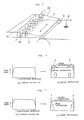
- a first preferred embodiment of the present invention will be explained with reference to Fig. 1. It is to be noted that in Fig. 1, since a headbox main body 1, header pipes 2, a jet port 3 and a wire 4 are identical to those used in the headbox in the prior art shown in Fig. 9, detailed description thereof will be omitted, and in the following only characteristic points of the present invention will be described.
- Fig. 2 is a cross-section front view of a header pipe block 5, in which provision is made such that a flow rate through the end portion may be larger than a flow rate through the central portion, by selecting an inner diameter d 2 of a header pipe 2b in the end portion larger than an inner diameter d 1 of a header pipe 2a in the inside portion. While the header pipes 2b having the inner diameter d 2 are provided only in one column at each end in Fig.
- header pipes 2b may be provided in two columns at the respective ends, a number of header pipes having a larger inner diameter may be different between the respective ends, the inner diameter of the header pipes may be different between the upper ones and the lower ones, or the size of the inner diameter may be varied into three or more kinds.
- Fig. 3 shows a B - B cross-section in Fig. 1, in which provision is made such that a part of the raw material at the end portions within the headbox can be extracted to the outside of the headbox through pipings 7 disposed symmetrically at the opposite ends on the upstream side of a slit-shaped jet port 3. Since the inner pressure of the headbox is higher than the atmospheric pressure, provided that the inner diameter of the pipings 7 is chosen sufficiently large, the raw material can be extracted from the headbox merely by opening the pipings 7 to the atmosphere.
- Fig. 4 shows a flow rate distribution along the widthwise direction and flow directions improved according to the present invention. If the flow rates at the end portions increase as compared to that in the central portion by disposing the header pipe block shown in Fig. 2, then as shown in Fig. 4(b) the flow rates at the end portions would become large as compared to that before correction shown in Fig. 4(a). By the way, since liquid would flow in such direction that its flow rate may become uniform according to a general property of a liquid flow, the flow directions would be directed inwards as shown in Fig. 4(b).
- Fig. 5 shows one modified embodiment, in which a sleeve 9 is fitted to the inside of the header pipe 2 in such manner that the sleeve may not slip out due to the pressure of the raw material.
- the flow rates through the end portions can be made larger than the flow rate through the central portion.
- flow rate balance between the end portions and the central portion as shown in Fig. 4(c) can be changed in a relatively simple manner by replacing the sleeves 9.
- a tube 10 made of elastic material such as rubber or the like is disposed inside of the header pipe 2, and by applying a pressure to the inside of the tube 10 through a duct 11 the tube 10 is deformed as shown in Fig. 6(b).
- the flow rate through the header pipe in the end portion can be made larger than the flow rate through the header pipe in the central portion.
- the flow rate balance between the end portions and the central portion can be changed.
- a correction effect for the flow directions can be attained as shown in Fig. 4(c).
- Fig. 8 shows another preferred embodiment which is different from that shown in Fig. 7, in which owing to the fact that pipings 13 are inserted into the headbox as bent along the pond-sides 6, the fear of disturbing flow directions within the headbox is less than the embodiment shown in Fig. 7.
- the essence of the present invention resides in the header pipe block having header pipes which are preset in such manner that the flow rates through the header pipes in the end portions of the headbox may be larger than the flow rate through the header pipe in the central portion, and/or the pipings disposed at the end portions of the flow passageway and capable of feeding the liquid in the headbox, and the pipings capable of extracting the raw material in the headbox to the outside from the end portions of the flow passageway.
- the jet flow directions of the headbox can be aligned in the same direction. According to results of experiments, flow directions directed outwards by 0.2° before correction became to direct inwards by 0.1° by supplementing the raw material to increase the flow rates at the opposite end portions, and furthermore, by extracting the raw material to decrease the flow rates at the opposite end portions, the jet directions could be aligned in the same direction.
- orientation angles of fibers of ⁇ 4° prior to correction were improved up to ⁇ 2° or less. It is to be noted that the orientation angles of fibers as referred to above are experimental values measured by a sonic sheet tester.
Landscapes
- Paper (AREA)
Applications Claiming Priority (2)
| Application Number | Priority Date | Filing Date | Title |
|---|---|---|---|
| JP2044815A JPH03249297A (ja) | 1990-02-26 | 1990-02-26 | 抄紙機ヘッドボックスの流向調整方法 |
| JP44815/90 | 1990-02-26 |
Publications (1)
| Publication Number | Publication Date |
|---|---|
| EP0445564A1 true EP0445564A1 (fr) | 1991-09-11 |
Family
ID=12701929
Family Applications (1)
| Application Number | Title | Priority Date | Filing Date |
|---|---|---|---|
| EP19910102273 Withdrawn EP0445564A1 (fr) | 1990-02-26 | 1991-02-18 | Procédé de régulation de la direction d'écoulement d'une caisse de tête dans une machine à papier |
Country Status (4)
| Country | Link |
|---|---|
| EP (1) | EP0445564A1 (fr) |
| JP (1) | JPH03249297A (fr) |
| KR (1) | KR930007859B1 (fr) |
| FI (1) | FI910856A7 (fr) |
Cited By (10)
| Publication number | Priority date | Publication date | Assignee | Title |
|---|---|---|---|---|
| EP0595325A1 (fr) * | 1992-10-29 | 1994-05-04 | Mitsubishi Jukogyo Kabushiki Kaisha | Dispositif pour la régulation du débit dans les parties latérales d'une caisse de tête pour machine à papier |
| WO1995008024A1 (fr) * | 1993-09-17 | 1995-03-23 | Beloit Technologies, Inc. | Procede d'orientation des fibres |
| EP0857816A1 (fr) * | 1997-01-14 | 1998-08-12 | Valmet Corporation | Caisse de tête d'une machine à papier avec alimentation en eau blanche par les cÔtes latéraux |
| DE19737646A1 (de) * | 1997-08-29 | 1999-03-04 | Voith Sulzer Papiermasch Gmbh | Blattbildungssystem mit Formatschilden |
| US6294051B1 (en) * | 1999-04-13 | 2001-09-25 | Kimberly-Clark Worldwide, Inc. | Method for improving the edge strength of a fibrous mat |
| EP2017383A2 (fr) | 2007-07-20 | 2009-01-21 | Voith Patent GmbH | Dispositif destiné à la fabrication d'une bande de matière fibreuse |
| DE102007034766A1 (de) | 2007-07-25 | 2009-01-29 | Voith Patent Gmbh | Vorrichtung und ein Verfahren zur Online-Regelung des Faserorientierungsquerprofils |
| DE102007036956A1 (de) | 2007-08-04 | 2009-02-05 | Voith Patent Gmbh | Maschine zur Herstellung einer Faserstoffbahn |
| AT505931B1 (de) * | 2007-11-19 | 2009-05-15 | Andritz Ag Maschf | Blattbildungsverfahren und nasspartie zur herstellung einer faserstoffbahn |
| EP2063020A4 (fr) * | 2006-09-05 | 2012-04-25 | Yokogawa Electric Corp | Procédé de simulation, procédé de commande d'orientation de fibre et dispositif de commande d'orientation de fibre |
Families Citing this family (1)
| Publication number | Priority date | Publication date | Assignee | Title |
|---|---|---|---|---|
| JP2011001668A (ja) * | 2009-06-22 | 2011-01-06 | Voith Patent Gmbh | 洗浄機用ヘッドボックス |
Citations (6)
| Publication number | Priority date | Publication date | Assignee | Title |
|---|---|---|---|---|
| GB1148674A (en) * | 1965-08-04 | 1969-04-16 | Beloit Corp | Improvements in a headbox of a papermaking machine |
| WO1986001844A1 (fr) * | 1984-09-19 | 1986-03-27 | Sulzer-Escher Wyss Gmbh | Systeme de caisse de tete pour machine a papier, et procede pour son utilisation |
| EP0232604A1 (fr) * | 1985-12-13 | 1987-08-19 | Valmet-Ahlstrom Inc. | Caisse de tête pour une machine à papier |
| AT384633B (de) * | 1986-05-12 | 1987-12-10 | Albert Hans | Stoffauflauf fuer papiermaschinen |
| WO1988008896A1 (fr) * | 1987-05-14 | 1988-11-17 | Beloit Corporation | Boite de tete |
| WO1989011561A1 (fr) * | 1988-05-17 | 1989-11-30 | J.M. Voith Ag | Caisse de tete pour machines a papier |
-
1990
- 1990-02-26 JP JP2044815A patent/JPH03249297A/ja active Pending
-
1991
- 1991-02-18 EP EP19910102273 patent/EP0445564A1/fr not_active Withdrawn
- 1991-02-22 FI FI910856A patent/FI910856A7/fi not_active Application Discontinuation
- 1991-02-26 KR KR1019910003089A patent/KR930007859B1/ko not_active Expired - Fee Related
Patent Citations (6)
| Publication number | Priority date | Publication date | Assignee | Title |
|---|---|---|---|---|
| GB1148674A (en) * | 1965-08-04 | 1969-04-16 | Beloit Corp | Improvements in a headbox of a papermaking machine |
| WO1986001844A1 (fr) * | 1984-09-19 | 1986-03-27 | Sulzer-Escher Wyss Gmbh | Systeme de caisse de tete pour machine a papier, et procede pour son utilisation |
| EP0232604A1 (fr) * | 1985-12-13 | 1987-08-19 | Valmet-Ahlstrom Inc. | Caisse de tête pour une machine à papier |
| AT384633B (de) * | 1986-05-12 | 1987-12-10 | Albert Hans | Stoffauflauf fuer papiermaschinen |
| WO1988008896A1 (fr) * | 1987-05-14 | 1988-11-17 | Beloit Corporation | Boite de tete |
| WO1989011561A1 (fr) * | 1988-05-17 | 1989-11-30 | J.M. Voith Ag | Caisse de tete pour machines a papier |
Cited By (18)
| Publication number | Priority date | Publication date | Assignee | Title |
|---|---|---|---|---|
| US5470439A (en) * | 1992-10-29 | 1995-11-28 | Mitsubishi Jukogyo Kabushiki Kaisha | End portion flow rate regulating apparatus for a paper machine headbox |
| EP0595325A1 (fr) * | 1992-10-29 | 1994-05-04 | Mitsubishi Jukogyo Kabushiki Kaisha | Dispositif pour la régulation du débit dans les parties latérales d'une caisse de tête pour machine à papier |
| WO1995008024A1 (fr) * | 1993-09-17 | 1995-03-23 | Beloit Technologies, Inc. | Procede d'orientation des fibres |
| EP0857816A1 (fr) * | 1997-01-14 | 1998-08-12 | Valmet Corporation | Caisse de tête d'une machine à papier avec alimentation en eau blanche par les cÔtes latéraux |
| DE19737646A1 (de) * | 1997-08-29 | 1999-03-04 | Voith Sulzer Papiermasch Gmbh | Blattbildungssystem mit Formatschilden |
| US6214169B1 (en) | 1997-08-29 | 2001-04-10 | Voith Sulzer Papiermaschinen Gmbh | Sheet formation system with deckle plates and method for reducing edge waves |
| US6294051B1 (en) * | 1999-04-13 | 2001-09-25 | Kimberly-Clark Worldwide, Inc. | Method for improving the edge strength of a fibrous mat |
| EP2063020A4 (fr) * | 2006-09-05 | 2012-04-25 | Yokogawa Electric Corp | Procédé de simulation, procédé de commande d'orientation de fibre et dispositif de commande d'orientation de fibre |
| US8214071B2 (en) | 2006-09-05 | 2012-07-03 | Yokogawa Electric Corporation | Simulation method, fiber orientation control method and fiber orientation control apparatus |
| DE102007033938A1 (de) | 2007-07-20 | 2009-01-22 | Voith Patent Gmbh | Vorrichtung zur Herstellung einer Faserstoffbahn |
| EP2017383A3 (fr) * | 2007-07-20 | 2012-06-13 | Voith Patent GmbH | Dispositif destiné à la fabrication d'une bande de matière fibreuse |
| EP2017383A2 (fr) | 2007-07-20 | 2009-01-21 | Voith Patent GmbH | Dispositif destiné à la fabrication d'une bande de matière fibreuse |
| EP2022889A2 (fr) | 2007-07-25 | 2009-02-11 | Voith Patent GmbH | Dispositif et procédé de réglage en ligne du profilé transversal d'orientation des fibres |
| DE102007034766A1 (de) | 2007-07-25 | 2009-01-29 | Voith Patent Gmbh | Vorrichtung und ein Verfahren zur Online-Regelung des Faserorientierungsquerprofils |
| DE102007036956A1 (de) | 2007-08-04 | 2009-02-05 | Voith Patent Gmbh | Maschine zur Herstellung einer Faserstoffbahn |
| EP2025808A2 (fr) | 2007-08-04 | 2009-02-18 | Voith Patent GmbH | Machine destinée à la fabrication d'une bande de matière fibreuse |
| AT505931B1 (de) * | 2007-11-19 | 2009-05-15 | Andritz Ag Maschf | Blattbildungsverfahren und nasspartie zur herstellung einer faserstoffbahn |
| EP2060675A3 (fr) * | 2007-11-19 | 2009-10-07 | Andritz AG | Procédé de formation de feuille et partie humide destinés à la fabrication d'une bande de matière fibreuse |
Also Published As
| Publication number | Publication date |
|---|---|
| JPH03249297A (ja) | 1991-11-07 |
| FI910856A0 (fi) | 1991-02-22 |
| FI910856A7 (fi) | 1991-08-27 |
| KR910021512A (ko) | 1991-12-20 |
| KR930007859B1 (ko) | 1993-08-20 |
Similar Documents
| Publication | Publication Date | Title |
|---|---|---|
| EP0445564A1 (fr) | Procédé de régulation de la direction d'écoulement d'une caisse de tête dans une machine à papier | |
| US3964639A (en) | Seed tube diffuser for a pneumatic seed planter | |
| DE2142394B2 (de) | Expansionsrohrventil | |
| EP1099793A3 (fr) | Procédé et dispositif pour la régulation d' une caisse de tête | |
| EP0687161A4 (fr) | Mesure du debit d'un fluide | |
| DE10135142A1 (de) | Vorrichtung zur Bestimmung zumindest eines Parameters eines in einer Leitung strömenden Mediums | |
| US2894581A (en) | Fluid stock distributor | |
| DE2701671B2 (de) | Einrichtung zum Plasmaspritzen | |
| JPH07256182A (ja) | ウェブ用塗布装置 | |
| CZ170299A3 (cs) | Sestava šnekového výměníku tepla | |
| NO141659B (no) | Massepaaloep for papirmaskin. | |
| GB2088911A (en) | A method for conveying a flexible thread by means of a pressurized gas | |
| WO2004068019A1 (fr) | Dispositif antitortillement pour conduits de fluide a parois minces | |
| EP0123829A1 (fr) | Tuyère de texturation de fil | |
| JP2007513481A (ja) | 圧力低下が小さい小型燃料電池インレット燃料ガス分配器 | |
| JPH0192179A (ja) | 織物用繊維ストランドを圧縮し且フィード挾持部内へ自動的に導入する装置 | |
| EP0974010A1 (fr) | Pompe a jet aspirant | |
| US11112808B2 (en) | Fluid flow restrictor device | |
| JPH02213470A (ja) | 伸長部材を導くシーリング部材及びシーリング部材を備えた真空装置 | |
| EP0522708A2 (fr) | Débitmètre | |
| DE3019103A1 (de) | Vorrichtung zum filtern von materialteilchen aus einem gasstrom | |
| US10663890B2 (en) | Developer inlets | |
| EP3691950A1 (fr) | Dispositif d'écoulement et procédé de commande et/ou de réglage d'une contrepression dans un dispositif pneumatique de transport de sable pour un véhicule ferroviaire et dispositif de transport de sable doté d'un dispositif d'écoulement | |
| DE102004005760A1 (de) | Durchfluss-Messvorrichtung | |
| JP3566405B2 (ja) | オリフィス流量計 |
Legal Events
| Date | Code | Title | Description |
|---|---|---|---|
| PUAI | Public reference made under article 153(3) epc to a published international application that has entered the european phase |
Free format text: ORIGINAL CODE: 0009012 |
|
| 17P | Request for examination filed |
Effective date: 19910315 |
|
| AK | Designated contracting states |
Kind code of ref document: A1 Designated state(s): DE FR GB IT |
|
| RIN1 | Information on inventor provided before grant (corrected) |
Inventor name: MAKINO, TETSUO, C/O MIHARA MACHINERY WORKS Inventor name: KURAGASAKI, MUTSUO, NAGASAKI TECHNICAL INSTITUTE Inventor name: OGAWA, HIROSHI Inventor name: FUJITA, NORIO, C/O MIHARA MACHINERY WORKS Inventor name: EGUCHI, AKIRA, HIROSHIMA TECH, INST. MITSUBISHI |
|
| 17Q | First examination report despatched |
Effective date: 19930803 |
|
| STAA | Information on the status of an ep patent application or granted ep patent |
Free format text: STATUS: THE APPLICATION IS DEEMED TO BE WITHDRAWN |
|
| 18D | Application deemed to be withdrawn |
Effective date: 19930814 |