EP0445568A1 - Verfahren zur Herstellung einer Schleifscheibe zum Schleifen von Brillenglasrändern - Google Patents
Verfahren zur Herstellung einer Schleifscheibe zum Schleifen von Brillenglasrändern Download PDFInfo
- Publication number
- EP0445568A1 EP0445568A1 EP91102312A EP91102312A EP0445568A1 EP 0445568 A1 EP0445568 A1 EP 0445568A1 EP 91102312 A EP91102312 A EP 91102312A EP 91102312 A EP91102312 A EP 91102312A EP 0445568 A1 EP0445568 A1 EP 0445568A1
- Authority
- EP
- European Patent Office
- Prior art keywords
- grinding wheel
- ring
- wheel according
- grinding
- base body
- Prior art date
- Legal status (The legal status is an assumption and is not a legal conclusion. Google has not performed a legal analysis and makes no representation as to the accuracy of the status listed.)
- Granted
Links
- 238000000227 grinding Methods 0.000 title claims abstract description 68
- 238000004519 manufacturing process Methods 0.000 title description 2
- 238000000034 method Methods 0.000 title description 2
- 229910052751 metal Inorganic materials 0.000 claims abstract description 26
- 239000002184 metal Substances 0.000 claims abstract description 26
- 239000004033 plastic Substances 0.000 claims abstract description 18
- 229910003460 diamond Inorganic materials 0.000 claims abstract description 15
- 239000010432 diamond Substances 0.000 claims abstract description 15
- 239000007769 metal material Substances 0.000 claims abstract description 12
- 238000005245 sintering Methods 0.000 claims abstract description 7
- KUNSUQLRTQLHQQ-UHFFFAOYSA-N copper tin Chemical compound [Cu].[Sn] KUNSUQLRTQLHQQ-UHFFFAOYSA-N 0.000 claims description 19
- 229910000906 Bronze Inorganic materials 0.000 claims description 16
- 239000010974 bronze Substances 0.000 claims description 16
- 239000000945 filler Substances 0.000 claims description 12
- RYGMFSIKBFXOCR-UHFFFAOYSA-N Copper Chemical compound [Cu] RYGMFSIKBFXOCR-UHFFFAOYSA-N 0.000 claims description 11
- 229910000831 Steel Inorganic materials 0.000 claims description 11
- 239000010959 steel Substances 0.000 claims description 11
- 239000010949 copper Substances 0.000 claims description 9
- 229910052802 copper Inorganic materials 0.000 claims description 9
- PXHVJJICTQNCMI-UHFFFAOYSA-N Nickel Chemical compound [Ni] PXHVJJICTQNCMI-UHFFFAOYSA-N 0.000 claims description 8
- 229910052782 aluminium Inorganic materials 0.000 claims description 7
- XAGFODPZIPBFFR-UHFFFAOYSA-N aluminium Chemical compound [Al] XAGFODPZIPBFFR-UHFFFAOYSA-N 0.000 claims description 7
- 150000002739 metals Chemical class 0.000 claims description 6
- 229920001568 phenolic resin Polymers 0.000 claims description 5
- 229920003002 synthetic resin Polymers 0.000 claims description 5
- 239000000057 synthetic resin Substances 0.000 claims description 5
- 229910052759 nickel Inorganic materials 0.000 claims description 4
- 239000005011 phenolic resin Substances 0.000 claims description 4
- 239000004917 carbon fiber Substances 0.000 claims description 3
- 239000003365 glass fiber Substances 0.000 claims description 3
- 229920001342 Bakelite® Polymers 0.000 claims description 2
- OKTJSMMVPCPJKN-UHFFFAOYSA-N Carbon Chemical compound [C] OKTJSMMVPCPJKN-UHFFFAOYSA-N 0.000 claims description 2
- 239000010425 asbestos Substances 0.000 claims description 2
- 239000004637 bakelite Substances 0.000 claims description 2
- 229910052799 carbon Inorganic materials 0.000 claims description 2
- 239000007859 condensation product Substances 0.000 claims description 2
- 239000000835 fiber Substances 0.000 claims description 2
- 239000002657 fibrous material Substances 0.000 claims description 2
- SLGWESQGEUXWJQ-UHFFFAOYSA-N formaldehyde;phenol Chemical compound O=C.OC1=CC=CC=C1 SLGWESQGEUXWJQ-UHFFFAOYSA-N 0.000 claims description 2
- 229910001092 metal group alloy Inorganic materials 0.000 claims description 2
- 229910052895 riebeckite Inorganic materials 0.000 claims description 2
- 239000000126 substance Substances 0.000 claims description 2
- 239000011248 coating agent Substances 0.000 description 31
- 238000000576 coating method Methods 0.000 description 31
- 238000013016 damping Methods 0.000 description 8
- 238000005304 joining Methods 0.000 description 8
- 239000000463 material Substances 0.000 description 8
- 230000017525 heat dissipation Effects 0.000 description 7
- 238000013461 design Methods 0.000 description 6
- 239000011521 glass Substances 0.000 description 6
- 239000010410 layer Substances 0.000 description 5
- 230000002349 favourable effect Effects 0.000 description 4
- 239000002245 particle Substances 0.000 description 4
- 230000002093 peripheral effect Effects 0.000 description 4
- 238000012545 processing Methods 0.000 description 4
- 229920005989 resin Polymers 0.000 description 4
- 239000011347 resin Substances 0.000 description 4
- 229920001187 thermosetting polymer Polymers 0.000 description 4
- KXGFMDJXCMQABM-UHFFFAOYSA-N 2-methoxy-6-methylphenol Chemical compound [CH]OC1=CC=CC([CH])=C1O KXGFMDJXCMQABM-UHFFFAOYSA-N 0.000 description 3
- 239000011230 binding agent Substances 0.000 description 3
- 238000004026 adhesive bonding Methods 0.000 description 2
- 230000000694 effects Effects 0.000 description 2
- 238000003754 machining Methods 0.000 description 2
- 229920001169 thermoplastic Polymers 0.000 description 2
- 239000004416 thermosoftening plastic Substances 0.000 description 2
- 238000012546 transfer Methods 0.000 description 2
- -1 Bakelite) Chemical compound 0.000 description 1
- 229920000049 Carbon (fiber) Polymers 0.000 description 1
- BQCADISMDOOEFD-UHFFFAOYSA-N Silver Chemical compound [Ag] BQCADISMDOOEFD-UHFFFAOYSA-N 0.000 description 1
- 239000012790 adhesive layer Substances 0.000 description 1
- 230000002411 adverse Effects 0.000 description 1
- 230000005540 biological transmission Effects 0.000 description 1
- 229910017052 cobalt Inorganic materials 0.000 description 1
- 239000010941 cobalt Substances 0.000 description 1
- GUTLYIVDDKVIGB-UHFFFAOYSA-N cobalt atom Chemical compound [Co] GUTLYIVDDKVIGB-UHFFFAOYSA-N 0.000 description 1
- 230000006378 damage Effects 0.000 description 1
- 238000000151 deposition Methods 0.000 description 1
- 238000005246 galvanizing Methods 0.000 description 1
- 239000002923 metal particle Substances 0.000 description 1
- 238000002203 pretreatment Methods 0.000 description 1
- 229910052709 silver Inorganic materials 0.000 description 1
- 239000004332 silver Substances 0.000 description 1
- 238000013517 stratification Methods 0.000 description 1
Images
Classifications
-
- B—PERFORMING OPERATIONS; TRANSPORTING
- B24—GRINDING; POLISHING
- B24B—MACHINES, DEVICES, OR PROCESSES FOR GRINDING OR POLISHING; DRESSING OR CONDITIONING OF ABRADING SURFACES; FEEDING OF GRINDING, POLISHING, OR LAPPING AGENTS
- B24B9/00—Machines or devices designed for grinding edges or bevels on work or for removing burrs; Accessories therefor
- B24B9/02—Machines or devices designed for grinding edges or bevels on work or for removing burrs; Accessories therefor characterised by a special design with respect to properties of materials specific to articles to be ground
- B24B9/06—Machines or devices designed for grinding edges or bevels on work or for removing burrs; Accessories therefor characterised by a special design with respect to properties of materials specific to articles to be ground of non-metallic inorganic material, e.g. stone, ceramics, porcelain
- B24B9/08—Machines or devices designed for grinding edges or bevels on work or for removing burrs; Accessories therefor characterised by a special design with respect to properties of materials specific to articles to be ground of non-metallic inorganic material, e.g. stone, ceramics, porcelain of glass
- B24B9/14—Machines or devices designed for grinding edges or bevels on work or for removing burrs; Accessories therefor characterised by a special design with respect to properties of materials specific to articles to be ground of non-metallic inorganic material, e.g. stone, ceramics, porcelain of glass of optical work, e.g. lenses, prisms
-
- B—PERFORMING OPERATIONS; TRANSPORTING
- B24—GRINDING; POLISHING
- B24D—TOOLS FOR GRINDING, BUFFING OR SHARPENING
- B24D18/00—Manufacture of grinding tools or other grinding devices, e.g. wheels, not otherwise provided for
- B24D18/0018—Manufacture of grinding tools or other grinding devices, e.g. wheels, not otherwise provided for by electrolytic deposition
-
- B—PERFORMING OPERATIONS; TRANSPORTING
- B24—GRINDING; POLISHING
- B24D—TOOLS FOR GRINDING, BUFFING OR SHARPENING
- B24D5/00—Bonded abrasive wheels, or wheels with inserted abrasive blocks, designed for acting only by their periphery; Bushings or mountings therefor
Definitions
- the invention relates to a grinding wheel for grinding spectacle lens edges, containing a base body and a grinding surface made of diamond and metal. These are peripheral disks, but in particular also profiled disks.
- This abrasive coating made of diamond and metal already has a relatively low thickness in the order of magnitude of approximately 3 mm or less due to its production, diamond particles having a size of approximately 250 ⁇ m or smaller being distributed.
- Circumferential grinding wheels which have a base body and an abrasive coating in the above sense, the base body having a central hole with which it is clamped onto a spindle. This applies to all versions, whereby special perforation profiles are included.
- metal is bronze
- that of different types such as pure bronze, silver bronze, cobalt bronze, etc., is galvanically deposited Use nickel or, in extreme cases, also hard metal.
- base bodies made of steel and bronze were primarily used for a diamond and metal abrasive coating.
- the known lenses are particularly unsuitable when machining spectacle lens edges, because, according to the above considerations, they lead to rejects either due to the transmission of imbalances, rigid designs, inability to dampen, or from the outset asymmetrical designs.
- the invention has for its object to provide a grinding wheel of the type mentioned with high-precision grinding properties in terms of accuracy even when processing an extremely brittle and thin material under economic conditions.
- the base body consists essentially of plastic in a grinding wheel with a grinding surface made of diamond and metal and a ring made of a metallic material is arranged between the base body and the grinding surface.
- the damping is low and the joining problematic because the application of the abrasive coating to the steel ring requires an expensive pretreatment of the same.
- the abrasive coating is sintered on, for example if a bronze ring is deposited, there is a risk of the bronze ring collapsing under the temperature and pressure conditions when the abrasive coating is sintered on.
- the claimed design of a basic body essentially made of plastic, in connection with the interposed ring made of metallic material for the diamond and metal abrasive coating surprisingly brings about a vibration behavior with regard to damping or rigidity, which ensures a gentle material intervention.
- the depositing of the specified abrasive coating with a ring made of metallic material ensures symmetry and accuracy and, with the properties of the metallic material, also ensures particularly favorable heat dissipation in the disk. This is essential for a plastic core, be it with fillers. What is important, however, is the interposition of the ring made of metallic material of the specified properties to improve the joining ability, ie the circumferential strength and the engagement stability of the materials of the disk, which only ensures that a precision instrument is created.
- a particularly advantageous feature of the invention is that the metallic material of the ring has a strength that can withstand the forces that occur during sintering. This creates a cheap base.
- the metallic material of the ring is more heat resistant than the abrasive coating.
- the preferred embodiment is that the ring consists of copper.
- the ring consists of bronze, in particular tempered bronze.
- the ring is made of aluminum, and it should not be excluded that the ring is made of steel. This version is subject to the problems of joining described above, but otherwise has the stated advantages.
- the ring preferably has a thickness of up to 10% of the radius of the grinding wheel. This creates a sufficiently strong deposit for the sintering of the abrasive coating. This applies preferably to the more advantageous design of the ring made of copper.
- the thickness of the ring is in the order of 3 to 10 mm.
- a combination between the abrasive coating and the metallic ring is already achieved.
- the base body is particularly advantageously made of a synthetic resin, in particular with fillers.
- Suitable thermoplastics and thermosets can be used as synthetic resins with regard to heat resistance and mechanical strength.
- Phenolic resin e.g. Bakelite
- Other phenol-formaldehyde condensation products are also included.
- Other thermoplastics and thermosets are possible, but the preferred embodiment leads to particularly favorable properties with regard to strength, machinability and elasticity through the chosen introduction of fillers. Most of these are fibrous materials.
- Carbon or glass fibers, optionally also asbestos fibers, and / or metals are particularly preferably provided as fillers.
- the invention is based on a grinding wheel with a diamond and metal abrasive coating. It is preferred that bronzes, electrodeposited nickel, hard metals or other metal alloys are mainly used as the metal in the abrasive coating. Bronze is particularly advantageous because it can be applied inexpensively and inexpensively to a metallic ring. Here, however, a steel ring is used less, which requires a special and expensive pretreatment to apply bronze.
- thermosets of the plastic base body have advantageous properties, especially in connection with a copper intermediate ring between the abrasive coating and the plastic base body.
- the preferred embodiment of the invention therefore consists in a grinding wheel with a sintered abrasive coating with diamond particles in the order of magnitude of 3 to 250 ⁇ m and a metal, in particular copper layer, which has a ring-shaped carrier with good thermal conductivity, based on a base body of the grinding wheel, forms.
- This disc is relatively light, but also sufficiently strong in terms of stress.
- the assembly consisting of the metallic ring and the abrasive coating, which are composed in particular by sintering on the main body.
- An advantageous embodiment is that the ring-shaped assembly is applied by shrinking. This also has the advantage of a tight contact with the circumferential surface of the base body, so that the machining, provided that it takes place under normal metallic tolerances, is facilitated. The shrinking creates an absolutely firm connection to the disk-shaped base body with the result that a high-precision tool is then created.
- the ring-shaped assembly made of abrasive coating and ring is glued to the base body, but the adhesive layer is then so small that elasticities are excluded. It must always be assumed that the invention relates to a peripheral disk.
- the invention creates a new grinding tool with special properties precisely in connection with the processing of glass. It can be assumed that the plastic base body can be machined precisely. It is less subject to external influences than metal, i.e. in the event of thermal expansion. These properties would be adversely affected if significant amounts of metal were introduced.
- a damping carrier with low mass is essential for grinding glass.
- the plastic is light and damping is. Even if there is an imbalance, it can be cushioned and there is no destruction of the processing material in the form of breakouts.
- Copper as a heat-conductive deposit has a high thermal conductivity and creates a secure connection.
- a direct joint is initially provided on the damping plastic base body with the metallic base.
- the plastic base body is designed with increased thermal conductivity on its circumference in the vicinity of the abrasive coating, including the metallic ring.
- thermally conductive substances in particular metals, are introduced into the plastic base body, which extend from the outside to a maximum of 20% of the radius in the body.
- the copper deposit mentioned several times above is an advantageous feature that is used in the preferred embodiment because the abrasive layer is used to the end and particularly good heat dissipation can be achieved.
- the grinding wheel is a profiled or cylindrical peripheral wheel, as can be used for grinding the edges of glasses.
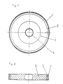
- it consists of an abrasive coating 1.
- This has a thickness of approximately 3 mm.
- It consists of diamond particles as grinding wheels, which are held in a binder, advantageously bronze.
- This is a sintered abrasive coating on a copper ring 2, which is designed as a metallic, ring-shaped carrier, has good thermal conductivity, but still has sufficient stability to support the abrasive coating in a defined manner.
- This copper ring 2 is arranged on a base body 3, which consists of synthetic resin, in particular of a phenolic resin according to the above statements. Fillers (not shown in the drawing) are advantageously arranged in this phenolic resin, which can consist of glass or carbon fibers.
- metal particles for example made of aluminum, particularly in the vicinity of the joint between the ring 2 and the base body 3, in order thereby to improve the heat transfer.
- the ring 2 can be applied to the base body 3 by gluing or shrinking.
- the base body has a central hole 4, by means of which it can be applied to a spindle of a grinding machine.
- the profiling which can be seen in FIG. 2, is suitable for grinding an eyeglass lens edge with a customary, projecting web.
- cylindrical, non-profiled grinding wheels are used.
Landscapes
- Engineering & Computer Science (AREA)
- Mechanical Engineering (AREA)
- Chemical & Material Sciences (AREA)
- Ceramic Engineering (AREA)
- Inorganic Chemistry (AREA)
- Manufacturing & Machinery (AREA)
- Polishing Bodies And Polishing Tools (AREA)
- Grinding And Polishing Of Tertiary Curved Surfaces And Surfaces With Complex Shapes (AREA)
Abstract
Description
- Die Erfindung betrifft eine Schleifscheibe zum Schleifen von Brillenglasrändern, enthaltend einen Grundkörper und einen Schleifbelag aus Diamant und Metall. Hierbei handelt es sich um Umfangsscheiben, insbesondere aber auch um Profilscheiben.
- Dieser Schleifbelag aus Diamant und Metall hat schon aufgrund seiner Herstellung eine relativ geringe Stärke in der Größenordnung von etwa 3 mm oder geringer, wobei Diamantpartikel in einer Größe von etwa 250 µm oder kleiner verteilt sind.
- Das Schleifen von Brillenglasrändern bringt erhebliche Probleme mit sich. Vom Material her ist Brillenglas sehr spröde. Es bricht bei schon geringen Unregelmäßigkeiten. Außerdem handelt es sich um ein dünnes Material, das keine große seitliche Widerstandskraft hat. Unwuchten des Schleifkörpers etc. führen bei einem solchen Material zu erheblichen Ausschußmengen.
- Zu berücksichtigen ist dabei auch, daß gerade in der Anwendung an Brillengläsern kleine Maschinen mit dünnen Spindeln eingesetzt sind. Bei solchen Maschinen spielt das Gewicht einer Schleifscheibe eine erhebliche Rolle.
- Es sind Umfangsschleifscheiben bekannt, die in obigem Sinne einen Grundkörper und einen Schleifbelag haben, wobei der Grundkörper ein zentrisches Loch aufweist, mit dem er auf eine Spindel aufgespannt wird. Das gilt für alle Ausführungen, wobei besondere Lochprofilierungen einbezogen werden.
- Bei bekannten Schleifscheiben mit einem Schleifbelag, der aus Diamant und Harz besteht, was außerhalb obigen Angaben liegt, sind Grundkörper aus Kunstharz mit metallischen Füllern sowie mit natürlichen Füllstoffen, sowie auch aus Aluminium oder Stahl, bekannt. Solche Schleifscheiben sind insbesondere in der oben genannten Anwendung problematisch. Das Harz im Schleifbelag bildet keine genügend stabile Bindungsgrundlage für das Feinschleifen eines extrem spröden, dünnen Materials.
- Für bekannte Grundkörper gilt, daß insgesamt metallische Grundkörper erhebliches Gewicht haben. Wenn auch Aluminium für den Grundkörper nun schon geringeres Gewicht als Stahl hat, so liegt doch dann immer eine problematische Fügung zwischen dem Schleifbelag mit metallischem Binder und Aluminium vor. Zwar kann die Fügung ausreichend sein, bildet aber keine optimale Lösung, unter anderem weil der Aufwand, diese Fügung herzustellen, größer ist.
- Bei gemäß einleitenden Ausführungen aus Diamant und Metall bestehenden Schleifbelägen ist bekannt, als Metall Bronze, und zwar unterschiedlicher Art, wie reine Bronze, Silberbronze, Kobaltbronze usw., galvanisch abgeschiedenes Nickel oder im Extremfall z.B. auch Hartmetall einzusetzen.
- Hierbei ergibt sich nun ein vorzüglicher Schleifbelag, der erhebliche Standfestigkeit, auch unter Druck und Wärmeeinfluß, hat. Aber bei diesen Schleifscheiben besteht der Grundkörper schon wegen der Fügung, jedenfalls im Bereich bis zu 95 % aller Scheiben, aus Stahl oder Bronze. Eine solche Scheibe ist schwer, symmetrisch zwar genau, aber sie ist nicht dämpfungsfähig und überträgt Unwuchten unnachgiebig.
- Wenn nun aber bei dem oben genannten Schleifbelag ein Grundkörper aus Harz auch mit metallischen Füllern verwendet würde, dann entsteht bei der Fügung, insbesondere durch Hinterpressung, Klebung oder auch Aufschrumpfung, eine Verbindung, welche schon wegen der geringen Dicke des Schleifbelags die Symmetrie, d.h. Umfangsgenauigkeit der Schleifscheibe, nicht gewährleistet, so daß dann ein Schwingungsverhalten zu Nachteilen führen würde. Außerdem ergeben sich aufgrund der schlechten Wärmeleitfähigkeit des Harzes Probleme in der Wärmeabfuhr, insbesondere wenn der Schleifbelag aufgrund seines Verschleißes nur noch wenige Zehntel Millimeter dick ist und die beim Schleifen notwendigerweise erzeugte Wärme abgeleitet werden muß. Ein Aufsintern des Schleifbelages ist nicht möglich, weil ein solcher Grundkörper nicht die notwendige Standfestigkeit hat, um der Druck- und Wärmeeinwirkung eines Sintervorganges zu widerstehen. Aus diesem Grunde sind auch bei einem Schleifbelag aus Diamant und Metall in erster Linie Grundkörper aus Stahl und Bronze eingesetzt worden.
- Es ist zu berücksichtigen, daß bei bekannten Ausführungen mit Kunststoffgrundkörpern, auf denen unmittelbar der Schleifbelag angeordnet ist, unter dem Schleifdruck und der Wärmeeinwirkungen Verformungen entstehen, die eine feinfühlige Profilierung bei der Bearbeitung ausschließen.
- Bei Einsatz von Stahl sind dafür unwirtschaftliche und teure Vorbehandlungen, beispielsweise durch Galvanisierungen, notwendig. Dieses vermindert die Wirtschaftlichkeit. Eine solche Vorbehandlung ist aber nötig, um die Bronze des Schleifbelages auf Stahl haften zu lassen.
- Gerade bei der Bearbeitung von Brillenglasrändern sind die bekannten Scheiben nicht geeignet, weil sie gemäß obigen Gesichtspunkten entweder durch die Übertragung von Unwuchten, starre Ausführungen, Dämpfungsunfähigkeiten oder aber von vornherein asymmetrische Ausführungen zu Ausschuß führen.
- Der Erfindung liegt die Aufgabe zugrunde, eine Schleifscheibe der eingangs angegebenen Art mit hochpräzisen Schleifeigenschaften hinsichtlich der Genauigkeit auch bei Bearbeitung eines extrem spröden und dünnen Materials unter wirtschaftlichen Bedingungen zu schaffen.
- Diese Aufgabe wird dadurch gelöst, daß bei einer Schleifscheibe mit einem Schleifbelag aus Diamant und Metall der Grundkörper im wesentlichen aus Kunststoff besteht und zwischen Grundkörper und Schleifbelag ein Ring aus einem metallischen Material angeordnet ist.
- Hierdurch ergibt sich praktisch eine dreifache Schichtung der Umfangsscheibe. Eine solche Schichtung mag an sich bekannt sein. Sie ist aber bekannt mit einem Kern oder Grundkörper aus Metall, insbesondere Aluminium, auf dem ein Stahlring oder Bronzering angeordnet ist, der den Schleifbelag hinterlegt. Hierbei ergibt sich eine verhältnismäßig harte Ausführung.
- Bei diesen Dreifachschichtungen ist die Dämpfung gering, und die Fügung problematisch, weil die Aufbringung des Schleifbelages auf den Stahlring eine teure Vorbehandlung desselben bedingt. Außerdem besteht bei der Aufsinterung des Schleifbelages, wenn etwa ein Bronzering hinterlegt ist, die Gefahr des Einbruchs des Bronzeringes unter den Temperatur- und Druckbedingungen bei der Aufsinterung des Schleifbelages.
- Diese Ausführungen sind außerdem schwer und führen zu Rückwirkungen auf die Maschinenausstattung, die gerade beim Randschleifen von Brillengläsern verhältnismäßig klein und leicht gehalten ist. Außerdem ergeben sich auch aus der geringen Dämpfung bei Unwuchten und fehlender Anpassung noch zusätzliche Rückwirkungen auf die Maschinen, Schleifscheiben und Brillengläser.
- Die beanspruchte Ausführung eines Grundkörpers im wesentlichen aus Kunststoff bringt gerade in Verbindung mit dem zwischengeschalteten Ring aus metallischem Material zum Schleifbelag aus Diamant und Metall überraschend ein Schwingungsverhalten hinsichtlich der Dämpfung oder auch Steifigkeit mit sich, das einen schonenden Materialeingriff gewährleistet. Die Hinterlegung des angegebenen Schleifbelages mit einem Ring aus metallischem Material sichert dabei die Symmetrie und Genauigkeit und gewährleistet mit den Eigenschaften des metallischen Materials auch eine besonders günstige Wärmeabführung in der Scheibe. Das ist für einen Kunststoffkern, sei er auch mit Füllstoffen versehen, wesentlich. Wichtig ist aber durch die Zwischenschaltung des Ringes aus metallischem Material der angegebenen Eigenschaften die Verbesserung der Fügbarkeit, d.h. der Umfangsfestigkeit und Eingriffsstandfestigkeit der Materialien der Scheibe, die erst gewährleistet, daß ein Präzisionsinstrument geschaffen wird.
- Bei der Verwendung eines Kunststoff-Grundkörpers und metallischen Zwischenringes in Verbindung mit einem Schleifbelag aus Diamant und Metall, Bronze, galvanischem Nickel oder Hartmetall ergibt sich schon hinsichtlich der Fügbarkeit, des Schwingungsverhaltens und der symmetrischen Genauigkeit bei guter Wärmeabführung eine besonders günstige Lösung.
- Ein besonders vorteilhaftes Merkmal der Erfindung liegt insofern darin, daß das metallische Material des Ringes eine Festigkeit aufweist, die die bei einer Aufsinterung auftretenden Kräfte aushält. Hierdurch wird bereits eine günstige Unterlage geschaffen.
- Ferner wird bevorzugt, daß das metallische Material des Ringes wärmefester als der Schleifbelag ist.
- Sowohl hinsichtlich der Wärmeabführung, der Fügbarkeit und des Dämpfungsverhaltens liegt die bevorzugte Ausführungsform darin, daß der Ring aus Kupfer besteht. Nicht ausgeschlossen wird in einer auch noch zweckmäßigen Ausgestaltung, daß der Ring aus Bronze, insbesondere vergüteter Bronze besteht. Einbezogen wird ferner, daß der Ring aus Aluminium besteht, wobei auch nicht ausgeschlossen sein soll, daß der Ring aus Stahl besteht. Diese Ausführung unterliegt den oben angeführten Problemen der Fügung, hat aber sonst die angegebenen Vorteile.
- Letzteres ist aber unwirtschaftlich und führt auch dazu, daß die Anpassungsfähigkeit, d.h. die Dämpfungsfähigkeit der Scheibe herabgesetzt wird.
- Vorzugsweise weist der Ring eine Stärke bis zu 10 % des Radius der Schleifscheibe auf. Hierdurch wird eine genügend starke Hinterlegung für die Aufsinterung des Schleifbelags geschaffen. Dieses gilt bevorzugt für die vorteilhaftere Ausführung des Ringes aus Kupfer.
- Vorzugsweise, auch bei kleineren Scheiben, liegt die Stärke des Ringes in der Größenordnung von 3 bis 10 mm. Hierbei wird bereits eine Kombination zwischen Schleifbelag und metallischem Ring erreicht.
- Mit besonderem Vorteil besteht der Grundkörper aus einem Kunstharz, insbesondere mit Füllstoffen. Als Kunstharze können hinsichtlich Warmfestigkeit und mechanischer Festigkeit geeignete Thermo- und Duroplaste Verwendung finden. Als Duroplast wird Phenol-Harz, ( z.B. Bakelit) , eingetragenes Warenzeichen, bevorzugt. Einbezogen werden aber auch andere Phenol-Formaldehyd-Kondensationsprodukte. Andere Thermo- und Duroplaste sind möglich, aber die bevorzugte Ausführungsform führt zu besonders günstigen Eigenschaften hinsichtlich Festigkeit, Bearbeitungsfähigkeit und Elastizität durch die gewählte Einbringung von Füllstoffen. Dabei handelt es sich überwiegend um Faserstoffe.
- Besonders bevorzugt sind als Füllstoffe Kohlenstoff- oder Glasfasern, gegebenenfalls auch Asbestfasern, und/oder Metalle vorgesehen.
- Wie oben dargelegt, geht die Erfindung von einer Schleifscheibe mit einem Schleifbelag aus Diamant und Metall aus. Dabei wird bevorzugt, daß als Metall im Schleifbelag vorwiegend Bronzen, galvanisch niedergeschlagenes Nickel, Hartmetalle oder andere Metall-Legierungen verwendet werden. Bronze ist besonders vorteilhaft, weil sie preiswert und günstig auf einen metallischen Ring aufgebracht werden kann. Hierbei wird allerdings weniger ein Stahlring verwendet, welcher zur Aufbringung von Bronze einer besonderen und teuren Vorbehandlung bedarf.
- Günstige Fügungen ergeben sich zwischen Bronze als Binder des Schleifbelags und Kupfer des Ringes. Dabei zeichnet sich Kupfer durch eine sehr gute Wärmeleitfähigkeit aus.
- Schon die oben angegebenen Duroplaste des Kunststoff-Grund körpers haben vorteilhafte Eigenschaften, insbesondere in Verbindung mit einem Kupferzwischenring zwischen dem Schleifbelag und dem Kunststoff-Grundkörper.
- Die bevorzugte Ausführungsform der Erfindung besteht daher in einer Schleifscheibe mit einem gesinterten Schleifbelag mit Diamant-Partikeln in einer Größenordnung von 3 bis 250 µm und einer Metall-, insbesondere Kupferschicht, welche einen ringförmig definierten Träger mit guter Wärmeleitfähigkeit, bezogen auf einen Grundkörper der Schleifscheibe, bildet. Diese Scheibe ist verhältnismäßig leicht, aber auch genügend fest hinsichtlich der Beanspruchung.
- Es ergeben sich, insbesondere für die Baugruppe aus dem metallischen Ring und dem Schleifbelag, die insbesondere durch Sinterung zusammengesetzt sind, verschiedene Aufbringungsmöglichkeiten auf den Grundkörper. Dabei besteht eine vorteilhafte Ausführung darin, daß die ringförmig vorberei tete Baugruppe durch Aufschrumpfung aufgebracht ist. Dieses hat auch den Vorteil einer dichten Anlage an die Umfangsfläche des Grundkörpers, so daß dadurch die Bearbeitung, sofern sie unter metallisch üblichen Toleranzen erfolgt, erleichtert wird. Die Aufschrumpfung schafft eine absolut feste Verbindung zu dem scheibenförmigen Grundkörper mit dem Ergebnis, daß dann ein hochpräzise arbeitendes Werkzeug geschaffen wird.
- Nach einer anderen vorteilhaften Ausführung ist die ringförmige Baugruppe aus Schleifbelag und Ring auf den Grundkörper aufgeklebt, wobei aber die Klebeschicht dann so gering ist, daß Elastizitäten ausgeschlossen werden. Hierbei ist immer davon auszugehen, daß sich die Erfindung auf eine Umfangsscheibe bezieht.
- Die Erfindung schafft gerade im Zusammenhang mit der Bearbeitung von Glas ein neues Schleifwerkzeug mit besonderen Eigenschaften. Dabei kann davon ausgegangen werden, daß der Kunststoff-Grundkörper präzise zu bearbeiten ist. Er unter liegt weniger als Metall äußeren Einflüssen, d.h. bei Wärmeeinwirkung einer Ausdehnung. Diese Eigenschaften würden beeinträchtigt, wenn Metall in erheblichem Umfang eingebracht würde.
- Für das Schleifen von Glas ist ein dämpfender Träger mit geringer Masse wesentlich.
- Für die erfindungsgemäße Ausführung ist vorteilhaft davon auszugehen, daß der Kunststoff leicht und dämpfend ausgeführt ist. Selbst wenn eine Unwucht vorhanden wäre, kann sie abgefedert werden, und es kommt nicht zur Vernichtung des bearbeitenden Materials in Form von Ausbrüchen.
- Gute Wärmeabführung wird durch eine metallische Hinterlegung der Schleifschicht erreicht. Hierdurch kann die Schleifschicht bis zum Verbrauch auch der letzten, relativ teuren Diamant-Partikel abgearbeitet werden.
- Kupfer als wärmeleitende Hinterlegung weist dabei eine hohe Wärmeleitfähigkeit auf und stellt eine sichere Verbindung her. Hierbei ist zunächst mit der metallischen Unterlage eine unmittelbare Fügung auf dem dämpfenden Kunststoff-Grundkörper vorgesehen.
- Einbezogen wird dabei eben mit Vorteil die Zwischenschaltung eines metallischen Belages. Ohne diesen wären zum Wärmeübergang besondere Eigenschaften des Kunststoff-Grundkörpers erforderlich, die nicht oder nur sehr schwer zu verwirklichen wären.
- Bevorzugt wird in einer besonderen Ausgestaltung, daß der Kunststoff-Grundkörper an seinem Umfang in der Nachbarschaft des Schleifbelages einschließlich des metallischen Ringes mit erhöhter Wärmeleitfähigkeit ausgeführt ist.
- Zur Verbesserung der Wärmeabführung sind in einer vorteilhaften Ausführung in den Kunststoff-Grundkörper am Umfang wärmeleitfähige Substanzen, insbesondere Metalle eingebracht, die sich im Körper auf einen Bereich bis höchstens 20 % des Radius von außen erstrecken.
- Die oben mehrfach angesprochene Kupferhinterlegung stellt ein vorteilhaftes Merkmal dar, das in der bevorzugten Ausführung angewendet wird, weil die Schleifschicht bis zu Ende ausgenutzt und auch eine besonders gute Wärmeabführung erreicht werden kann.
- Die Erfindung wird im folgenden anhand eines Ausführungsbeispiels erläutert, das in der Zeichnung dargestellt ist. In der Zeichnung zeigen:
- Fig. 1
- eine Seitenansicht einer Schleifscheibe mit vergrößerten Proportionen, soweit es sich um eine Scheibe zur Anwendung für das Randschleifen von Brillen handelt;
- Fig. 2
- einen Schnitt in Teildarstellung längs der Linie II-II durch Fig. 1.
- Die Schleifscheibe ist eine profilierte oder zylindrische Umfangsscheibe, wie sie zum Schleifen von Brillenglasrändern eingesetzt werden kann. Sie besteht in der vorteilhaften, dargestellten Ausführung aus einem Schleifbelag 1. Dieser hat eine Stärke von etwa 3 mm. Er besteht aus Diamant-Partikeln als Schleifkörper, die in einem Binder, vorteilhaft Bronze, gehalten sind. Hierbei handelt es sich um einen gesinterten Schleifbelag auf einem Kupferring 2, der als metallischer, ringförmiger Träger ausgeführt ist, gute Wärmeleitfähigkeit hat, aber noch ausreichende Stabilität zur definierten Abstützung des Schleifbelags.
- Dieser Kupferring 2 ist auf einem Grundkörper 3 angeordnet, der aus Kunstharz, insbesondere aus einem Phenol-Harz gemäß obigen Darlegungen besteht. In diesem Phenol-Harz sind vorteilhaft in der Zeichnung nicht dargestellte Füllstoffe angeordnet, die aus Glas- oder Kohlenstoff-Fasern bestehen können.
- Es besteht ferner die Möglichkeit, Metallpartikel, beispielsweise aus Aluminium, besonders in der Nähe der Fügung zwischen dem Ring 2 und dem Grundkörper 3 anzuordnen, um dadurch den Wärmeübergang zu verbessern.
- Der Ring 2 kann auf den Grundkörper 3 durch Klebung oder Aufschrumpfung aufgebracht werden.
- Der Grundkörper hat ein mittleres Loch 4, mittels dessen er auf eine Spindel einer Schleifmaschine aufgebracht werden kann.
- Die Profilierung, die aus Fig. 2 erkennbar ist, ist geeignet, um einen Brillenglasrand mit einem üblichen, hervorspringenden Steg zu schleifen, zum Vorschleifen werden zylindriche, nichtprofilierte Schleifscheiben verwendet.
Claims (17)
- Schleifscheibe zum Schleifen von Brillenglasrändern, enthaltend einen Grundkörper und einen Schleifbelag aus Diamant und Metall, dadurch gekennzeichnet, daß der Grundkörper (3) im wesentlichen aus Kunststoff besteht und zwischen Grundkörper (3) und Schleifbelag (1) ein Ring (2) aus einem metallischen Material angeordnet ist.
- Schleifscheibe nach Anspruch 1, dadurch gekennzeichnet, daß das metallische Material des Ringes (2) eine Festigkeit aufweist, die die bei einer Aufsinterung auftretenden Kräfte aushält.
- Schleifscheibe nach Anspruch 1, dadurch gekennzeichnet, daß das metallische Material des Ringes (2) wärmefester als der Schleifbelag ist.
- Schleifscheibe nach einem der Ansprüche 1 bis 3, dadurch gekennzeichnet, daß der Ring (2) aus Kupfer besteht.
- Schleifscheibe nach einem der Ansprüche 1 bis 3, dadurch gekennzeichnet, daß der Ring (2) aus Bronze, insbesondere vergüteter Bronze besteht.
- Schleifscheibe nach einem der Ansprüche 1 bis 3, dadurch gekennzeichnet, daß der Ring (2) aus Aluminium besteht.
- Schleifscheibe nach einem der Ansprüche 1 bis 3, dadurch gekennzeichnet, daß der Ring (2) aus Stahl besteht.
- Schleifscheibe nach einem der Ansprüche 1 bis 7, dadurch gekennzeichnet, daß der Ring (2) eine Stärke bis zu 10 % des Radius der Schleifscheibe aufweist.
- Schleifscheibe nach einem der Ansprüche 1 bis 8, dadurch gekennzeichnet, daß die Stärke des Ringes (2) in der Größenordnung von 3 bis 10 mm liegt.
- Schleifscheibe nach einem der Ansprüche 1 bis 9, dadurch gekennzeichnet, daß der Grundkörper (3) aus einem Kunstharz, inbesondere mit Füllstoffen besteht.
- Schleifscheibe nach Anspruch 10, dadurch gekennzeichnet, daß der Grundkörper (3) aus Phenol-Harz (z.B. Bakelit) besteht (Phenol-Formaldehyd-Kondensationsprodukte).
- Schleifscheibe nach Anspruch 10, dadurch gekennzeichnet, daß der Kunststoff-Grundkörper (3) mit Füllstoffen durchsetzt ist (vorwiegend Faserstoffe).
- Schleifscheibe nach Anspruch 12, dadurch gekennzeichnet, daß als Füllstoffe Kohlenstoff- oder Glasfasern, gegebenenfalls auch Asbestfasern, vorgesehen sind.
- Schleifscheibe nach Anspruch 12, dadurch gekennzeichnet, daß als Füllstoffe Metalle vorgesehen sind.
- Schleifscheibe nach einem der Ansprüche 1 bis 14, dadurch gekennzeichnet, daß als Metall im Schleifbelag (1) vorwiegend Bronzen, galvanisch niedergeschlagenes Nickel, Hartmetalle oder andere Metall-Legierungen verwendet werden.
- Schleifscheibe nach einem der Ansprüche 1 bis 15, dadurch gekennzeichnet, daß der Kunststoff-Grundkörper (3) an seinem Umfang in der Nachbarschaft des Schleifbelags (1) einschließlich des metallischen Ringes (2) mit erhöhter Wärmeleitfähigkeit ausgeführt ist.
- Schleifscheibe nach Anspruch 16, dadurch gekennzeichnet, daß in den Kunststoff-Grundkörper (3) am Umfang wärmeleitfähige Substanzen, insbesondere Metalle eingebracht sind, die sich im Körper auf einen Bereich bis höchstens 20 % des Radius von außen erstrecken.
Applications Claiming Priority (2)
| Application Number | Priority Date | Filing Date | Title |
|---|---|---|---|
| DE4006660A DE4006660A1 (de) | 1990-03-03 | 1990-03-03 | Schleifscheibe zum schleifen von brillenglasraendern |
| DE4006660 | 1990-03-03 |
Publications (2)
| Publication Number | Publication Date |
|---|---|
| EP0445568A1 true EP0445568A1 (de) | 1991-09-11 |
| EP0445568B1 EP0445568B1 (de) | 1994-08-10 |
Family
ID=6401327
Family Applications (1)
| Application Number | Title | Priority Date | Filing Date |
|---|---|---|---|
| EP91102312A Expired - Lifetime EP0445568B1 (de) | 1990-03-03 | 1991-02-19 | Verfahren zur Herstellung einer Schleifscheibe zum Schleifen von Brillenglasrändern |
Country Status (7)
| Country | Link |
|---|---|
| US (1) | US5645476A (de) |
| EP (1) | EP0445568B1 (de) |
| JP (1) | JP3196030B2 (de) |
| AT (1) | ATE109710T1 (de) |
| DE (2) | DE4006660A1 (de) |
| DK (1) | DK0445568T3 (de) |
| ES (1) | ES2058952T3 (de) |
Cited By (5)
| Publication number | Priority date | Publication date | Assignee | Title |
|---|---|---|---|---|
| WO1998001259A3 (en) * | 1996-07-05 | 1998-03-12 | Darex Corp | Precision drill sharpener and grinding wheel assembly therefor |
| WO1998030360A1 (de) * | 1997-01-13 | 1998-07-16 | Winter Cvd Technik Gmbh | Schleifkörper |
| EP1332013A4 (de) * | 2000-09-28 | 2005-01-05 | Inland Diamond Products Compan | Randschleifrad mit spanbeseitigung |
| AT518251A4 (de) * | 2016-03-15 | 2017-09-15 | Tyrolit - Schleifmittelwerke Swarovski K G | Schleifscheibe |
| CN108838910A (zh) * | 2018-06-21 | 2018-11-20 | 江苏赛扬精工科技有限责任公司 | 一种树脂基无心磨砂轮及其制备方法 |
Families Citing this family (7)
| Publication number | Priority date | Publication date | Assignee | Title |
|---|---|---|---|---|
| DE4334887C2 (de) * | 1993-02-02 | 1995-01-05 | Wernicke & Co Gmbh | Verwendung eines Schleifwerkzeugs zum Bearbeiten des Umfangsrandes und/oder deroptischen Oberfläche von Brillengläsern aus Kunststoff |
| JPH09103940A (ja) * | 1995-08-07 | 1997-04-22 | Ricoh Co Ltd | 電解インプロセスドレッシング研削砥石および電解インプロセスドレッシング研削方法および電解インプロセスドレッシング研削装置 |
| US5891206A (en) * | 1997-05-08 | 1999-04-06 | Norton Company | Sintered abrasive tools |
| ES2187142T3 (es) * | 1998-02-04 | 2003-05-16 | Unicorn Abrasives Ltd | Muela. |
| JP2003039331A (ja) | 2001-08-01 | 2003-02-13 | Noritake Co Ltd | 樹脂製コア部を有する砥石車とその製造方法及び再利用方法 |
| DE102017116851B4 (de) | 2017-07-25 | 2020-06-04 | Lukas-Erzett Vereinigte Schleif- Und Fräswerkzeugfabriken Gmbh & Co. Kg | Schleifwerkzeug und Verwendung eines solchen Schleifwerkzeuges |
| KR102948592B1 (ko) * | 2021-01-14 | 2026-04-03 | 현대자동차주식회사 | 연마를 위한 그라인딩 휠 |
Citations (10)
| Publication number | Priority date | Publication date | Assignee | Title |
|---|---|---|---|---|
| US2226607A (en) * | 1938-06-07 | 1940-12-31 | Gilmore | Abrasive surface and method of preparing the same |
| FR1087350A (fr) * | 1953-07-23 | 1955-02-23 | Outil abrasif et procédé de sa fabrication | |
| DE1020460B (de) * | 1951-07-19 | 1957-12-05 | Pilkington Brothers Ltd | Verwendung einer Kupferlegierung als Werkstoff fuer die Schleifflaechen von Schleifwerkzeugen fuer Tafelglas |
| US3957593A (en) * | 1975-01-31 | 1976-05-18 | Keene Corporation | Method of forming an abrasive tool |
| DE2716415A1 (de) * | 1977-04-14 | 1979-01-18 | Joern J Jessen | Methode zur herstellung von schleif- u.ae. koerpern- oder elementen |
| AT378345B (de) * | 1982-03-18 | 1985-07-25 | Swarovski Tyrolit Schleif | Schleifwerkzeug |
| DE3530974C1 (en) * | 1985-08-30 | 1987-03-05 | Wernicke & Co Gmbh | Grinding wheel for machining the edges of spectacle glasses, and a process for producing it |
| DE3537331A1 (de) * | 1985-10-19 | 1987-04-23 | Wernicke & Co Gmbh | Verfahren zum herstellen, insbesondere einer brillenglasrandschleifscheibe oder -ringscheibe |
| DE3533248C1 (en) * | 1985-09-18 | 1987-07-02 | Werner Foppe | Process for producing milling cutters by equipping with macro grains of abrasive materials, such as silicon carbide |
| SU449554A1 (ru) * | 1971-12-30 | 1990-01-07 | Предприятие П/Я Р-6543 | Алмазный прав щий ролик |
Family Cites Families (6)
| Publication number | Priority date | Publication date | Assignee | Title |
|---|---|---|---|---|
| US2275339A (en) * | 1941-02-08 | 1942-03-03 | Allison Company | Abrasive cutting wheel |
| US2475517A (en) * | 1946-08-13 | 1949-07-05 | Carborundum Co | Abrasive article of manufacture |
| US3290834A (en) * | 1964-07-15 | 1966-12-13 | Frederick W Lindblad | Grinding wheel |
| US3868233A (en) * | 1973-03-12 | 1975-02-25 | Norton Co | Grinding wheel core |
| US4010583A (en) * | 1974-05-28 | 1977-03-08 | Engelhard Minerals & Chemicals Corporation | Fixed-super-abrasive tool and method of manufacture thereof |
| US4037367A (en) * | 1975-12-22 | 1977-07-26 | Kruse James A | Grinding tool |
-
1990
- 1990-03-03 DE DE4006660A patent/DE4006660A1/de active Granted
-
1991
- 1991-02-19 ES ES91102312T patent/ES2058952T3/es not_active Expired - Lifetime
- 1991-02-19 DK DK91102312.5T patent/DK0445568T3/da active
- 1991-02-19 AT AT91102312T patent/ATE109710T1/de not_active IP Right Cessation
- 1991-02-19 EP EP91102312A patent/EP0445568B1/de not_active Expired - Lifetime
- 1991-02-19 DE DE59102461T patent/DE59102461D1/de not_active Expired - Fee Related
- 1991-03-04 JP JP06405691A patent/JP3196030B2/ja not_active Expired - Fee Related
-
1994
- 1994-06-06 US US08/254,346 patent/US5645476A/en not_active Expired - Lifetime
Patent Citations (10)
| Publication number | Priority date | Publication date | Assignee | Title |
|---|---|---|---|---|
| US2226607A (en) * | 1938-06-07 | 1940-12-31 | Gilmore | Abrasive surface and method of preparing the same |
| DE1020460B (de) * | 1951-07-19 | 1957-12-05 | Pilkington Brothers Ltd | Verwendung einer Kupferlegierung als Werkstoff fuer die Schleifflaechen von Schleifwerkzeugen fuer Tafelglas |
| FR1087350A (fr) * | 1953-07-23 | 1955-02-23 | Outil abrasif et procédé de sa fabrication | |
| SU449554A1 (ru) * | 1971-12-30 | 1990-01-07 | Предприятие П/Я Р-6543 | Алмазный прав щий ролик |
| US3957593A (en) * | 1975-01-31 | 1976-05-18 | Keene Corporation | Method of forming an abrasive tool |
| DE2716415A1 (de) * | 1977-04-14 | 1979-01-18 | Joern J Jessen | Methode zur herstellung von schleif- u.ae. koerpern- oder elementen |
| AT378345B (de) * | 1982-03-18 | 1985-07-25 | Swarovski Tyrolit Schleif | Schleifwerkzeug |
| DE3530974C1 (en) * | 1985-08-30 | 1987-03-05 | Wernicke & Co Gmbh | Grinding wheel for machining the edges of spectacle glasses, and a process for producing it |
| DE3533248C1 (en) * | 1985-09-18 | 1987-07-02 | Werner Foppe | Process for producing milling cutters by equipping with macro grains of abrasive materials, such as silicon carbide |
| DE3537331A1 (de) * | 1985-10-19 | 1987-04-23 | Wernicke & Co Gmbh | Verfahren zum herstellen, insbesondere einer brillenglasrandschleifscheibe oder -ringscheibe |
Non-Patent Citations (1)
| Title |
|---|
| SOVIET INVENTIONS ILLUSTRATED Section Mech Week 9036, 17 October 1990 Derwent World Patents Index; AN 1990-273056 * |
Cited By (8)
| Publication number | Priority date | Publication date | Assignee | Title |
|---|---|---|---|---|
| WO1998001259A3 (en) * | 1996-07-05 | 1998-03-12 | Darex Corp | Precision drill sharpener and grinding wheel assembly therefor |
| EP1234633A1 (de) * | 1996-07-05 | 2002-08-28 | David Bernard | Hochgenaue Bohrerschleifvorrichtung und Schleifscheibenaufbau dazu |
| WO1998030360A1 (de) * | 1997-01-13 | 1998-07-16 | Winter Cvd Technik Gmbh | Schleifkörper |
| EP1332013A4 (de) * | 2000-09-28 | 2005-01-05 | Inland Diamond Products Compan | Randschleifrad mit spanbeseitigung |
| EP1875980A1 (de) * | 2000-09-28 | 2008-01-09 | Inland Diamond Products Company | Winkelkantenrad mit Spanspielraum |
| AT518251A4 (de) * | 2016-03-15 | 2017-09-15 | Tyrolit - Schleifmittelwerke Swarovski K G | Schleifscheibe |
| AT518251B1 (de) * | 2016-03-15 | 2017-09-15 | Tyrolit - Schleifmittelwerke Swarovski K G | Schleifscheibe |
| CN108838910A (zh) * | 2018-06-21 | 2018-11-20 | 江苏赛扬精工科技有限责任公司 | 一种树脂基无心磨砂轮及其制备方法 |
Also Published As
| Publication number | Publication date |
|---|---|
| JPH04217462A (ja) | 1992-08-07 |
| DE4006660A1 (de) | 1991-09-05 |
| ES2058952T3 (es) | 1994-11-01 |
| ATE109710T1 (de) | 1994-08-15 |
| DK0445568T3 (da) | 1994-11-21 |
| DE4006660C2 (de) | 1992-10-08 |
| EP0445568B1 (de) | 1994-08-10 |
| DE59102461D1 (de) | 1994-09-15 |
| JP3196030B2 (ja) | 2001-08-06 |
| US5645476A (en) | 1997-07-08 |
Similar Documents
| Publication | Publication Date | Title |
|---|---|---|
| EP1013956B2 (de) | Bremseinheit | |
| DE3507638C2 (de) | Bürstendichtung | |
| EP0254941B1 (de) | Abrichtwerkzeug für Schleifscheiben | |
| EP0445568B1 (de) | Verfahren zur Herstellung einer Schleifscheibe zum Schleifen von Brillenglasrändern | |
| DE4032182A1 (de) | Verbundreibmaterial fuer bremsen | |
| EP0201760A1 (de) | Reibring, insbesondere für Scheiben- oder Trommelbremsen | |
| DE4338077C2 (de) | Honelement | |
| EP0605850B1 (de) | Stammblatt aus faserverstärktem Kunststoff für Kreissägeblätter und/oder Trennschleifscheiben | |
| EP3395502B1 (de) | Trägerkörper für ein schleif- oder ein schneidwerkzeug | |
| AT502285A1 (de) | Trennschleifring | |
| EP0898504B1 (de) | Schleifkörper | |
| DE19955009C2 (de) | Verfahren zur Herstellung von Garnituren für das mechanische Bearbeiten von suspendiertem Faserstoffmaterial | |
| DE4111238A1 (de) | Werkzeug zur zerspanung von werkstoffen | |
| DE4424203A1 (de) | Schleifscheibe zum Schleifen des Randes von Brillengläsern | |
| DE4408717A1 (de) | Schichtverbundelemente für den Verschleißschutz | |
| DE4106005A1 (de) | Schleif- oder trennwerkzeug und verfahren seiner herstellung | |
| DE3138163C2 (de) | ||
| DE2364869A1 (de) | Abtastnadel | |
| DE4341503A1 (de) | Vorrichtung zum Feinbearbeiten von Bohrungen | |
| DE19757242A1 (de) | Bohrwerkzeug für Bohrungen in Vollmaterial | |
| DE29711063U1 (de) | Schleifkörper | |
| DE102010026971B4 (de) | Rotationssymmetrisches Werkzeug, insbesondere Schleifwerkzeug | |
| CH720898B1 (de) | Schleifscheibe, insbesondere für die Bearbeitung von Verzahnungen vorzugsweise für die Herstellung eines Zahnrades | |
| DE2222620A1 (de) | Magnetkopf und Verfahren zu seiner Herstellung | |
| DE9103254U1 (de) | Flaschendrehteller |
Legal Events
| Date | Code | Title | Description |
|---|---|---|---|
| PUAI | Public reference made under article 153(3) epc to a published international application that has entered the european phase |
Free format text: ORIGINAL CODE: 0009012 |
|
| 17P | Request for examination filed |
Effective date: 19910618 |
|
| AK | Designated contracting states |
Kind code of ref document: A1 Designated state(s): AT BE CH DE DK ES FR GB GR IT LI NL SE |
|
| 17Q | First examination report despatched |
Effective date: 19921223 |
|
| GRAA | (expected) grant |
Free format text: ORIGINAL CODE: 0009210 |
|
| AK | Designated contracting states |
Kind code of ref document: B1 Designated state(s): AT BE CH DE DK ES FR GB GR IT LI NL SE |
|
| PG25 | Lapsed in a contracting state [announced via postgrant information from national office to epo] |
Ref country code: GR Free format text: LAPSE BECAUSE OF FAILURE TO SUBMIT A TRANSLATION OF THE DESCRIPTION OR TO PAY THE FEE WITHIN THE PRESCRIBED TIME-LIMIT Effective date: 19940810 |
|
| REF | Corresponds to: |
Ref document number: 109710 Country of ref document: AT Date of ref document: 19940815 Kind code of ref document: T |
|
| REF | Corresponds to: |
Ref document number: 59102461 Country of ref document: DE Date of ref document: 19940915 |
|
| REG | Reference to a national code |
Ref country code: ES Ref legal event code: FG2A Ref document number: 2058952 Country of ref document: ES Kind code of ref document: T3 |
|
| ITF | It: translation for a ep patent filed | ||
| GBT | Gb: translation of ep patent filed (gb section 77(6)(a)/1977) |
Effective date: 19941006 |
|
| REG | Reference to a national code |
Ref country code: DK Ref legal event code: T3 |
|
| ET | Fr: translation filed | ||
| EAL | Se: european patent in force in sweden |
Ref document number: 91102312.5 |
|
| PLBI | Opposition filed |
Free format text: ORIGINAL CODE: 0009260 |
|
| 26 | Opposition filed |
Opponent name: TRIEFUS FRANCE Effective date: 19950510 Opponent name: DIAMANT BOART DEUTSCHLAND GMBH Effective date: 19950505 |
|
| NLR1 | Nl: opposition has been filed with the epo |
Opponent name: TRIEFUS FRANCE Opponent name: DIAMANT BOART DEUTSCHLAND GMBH |
|
| PLBF | Reply of patent proprietor to notice(s) of opposition |
Free format text: ORIGINAL CODE: EPIDOS OBSO |
|
| REG | Reference to a national code |
Ref country code: FR Ref legal event code: TP |
|
| NLS | Nl: assignments of ep-patents |
Owner name: ERNST WINTER & SOHN DIAMANTWERKZEUGE GMBH & CO. |
|
| REG | Reference to a national code |
Ref country code: GB Ref legal event code: 732E |
|
| REG | Reference to a national code |
Ref country code: ES Ref legal event code: PC2A |
|
| PLBO | Opposition rejected |
Free format text: ORIGINAL CODE: EPIDOS REJO |
|
| PLAB | Opposition data, opponent's data or that of the opponent's representative modified |
Free format text: ORIGINAL CODE: 0009299OPPO |
|
| APAC | Appeal dossier modified |
Free format text: ORIGINAL CODE: EPIDOS NOAPO |
|
| APAE | Appeal reference modified |
Free format text: ORIGINAL CODE: EPIDOS REFNO |
|
| R26 | Opposition filed (corrected) |
Opponent name: WENDT GMBH * 19950510 TRIEFUS FRANCE Effective date: 19950505 |
|
| APAC | Appeal dossier modified |
Free format text: ORIGINAL CODE: EPIDOS NOAPO |
|
| NLR1 | Nl: opposition has been filed with the epo |
Opponent name: TRIEFUS FRANCE Opponent name: WENDT GMBH |
|
| REG | Reference to a national code |
Ref country code: GB Ref legal event code: IF02 |
|
| APAC | Appeal dossier modified |
Free format text: ORIGINAL CODE: EPIDOS NOAPO |
|
| PLBN | Opposition rejected |
Free format text: ORIGINAL CODE: 0009273 |
|
| STAA | Information on the status of an ep patent application or granted ep patent |
Free format text: STATUS: OPPOSITION REJECTED |
|
| 27O | Opposition rejected |
Effective date: 20020124 |
|
| NLR2 | Nl: decision of opposition | ||
| APAH | Appeal reference modified |
Free format text: ORIGINAL CODE: EPIDOSCREFNO |
|
| REG | Reference to a national code |
Ref country code: CH Ref legal event code: PCAR Free format text: ISLER & PEDRAZZINI AG;POSTFACH 1772;8027 ZUERICH (CH) |
|
| PGFP | Annual fee paid to national office [announced via postgrant information from national office to epo] |
Ref country code: ES Payment date: 20071203 Year of fee payment: 18 |
|
| PGFP | Annual fee paid to national office [announced via postgrant information from national office to epo] |
Ref country code: DK Payment date: 20080226 Year of fee payment: 18 Ref country code: CH Payment date: 20080304 Year of fee payment: 18 |
|
| PGFP | Annual fee paid to national office [announced via postgrant information from national office to epo] |
Ref country code: SE Payment date: 20080213 Year of fee payment: 18 Ref country code: GB Payment date: 20080213 Year of fee payment: 18 Ref country code: IT Payment date: 20080228 Year of fee payment: 18 Ref country code: NL Payment date: 20080229 Year of fee payment: 18 |
|
| PGFP | Annual fee paid to national office [announced via postgrant information from national office to epo] |
Ref country code: AT Payment date: 20080220 Year of fee payment: 18 |
|
| PGFP | Annual fee paid to national office [announced via postgrant information from national office to epo] |
Ref country code: DE Payment date: 20080408 Year of fee payment: 18 Ref country code: FR Payment date: 20071220 Year of fee payment: 18 |
|
| PGFP | Annual fee paid to national office [announced via postgrant information from national office to epo] |
Ref country code: BE Payment date: 20080205 Year of fee payment: 18 |
|
| BERE | Be: lapsed |
Owner name: ERNST *WINTER & SOHN DIAMANTWERKZEUGE G.M.B.H. & C Effective date: 20090228 |
|
| REG | Reference to a national code |
Ref country code: CH Ref legal event code: PL |
|
| EUG | Se: european patent has lapsed | ||
| REG | Reference to a national code |
Ref country code: DK Ref legal event code: EBP |
|
| GBPC | Gb: european patent ceased through non-payment of renewal fee |
Effective date: 20090219 |
|
| PG25 | Lapsed in a contracting state [announced via postgrant information from national office to epo] |
Ref country code: AT Free format text: LAPSE BECAUSE OF NON-PAYMENT OF DUE FEES Effective date: 20090219 Ref country code: LI Free format text: LAPSE BECAUSE OF NON-PAYMENT OF DUE FEES Effective date: 20090228 Ref country code: CH Free format text: LAPSE BECAUSE OF NON-PAYMENT OF DUE FEES Effective date: 20090228 |
|
| NLV4 | Nl: lapsed or anulled due to non-payment of the annual fee |
Effective date: 20090901 |
|
| REG | Reference to a national code |
Ref country code: FR Ref legal event code: ST Effective date: 20091030 |
|
| PG25 | Lapsed in a contracting state [announced via postgrant information from national office to epo] |
Ref country code: NL Free format text: LAPSE BECAUSE OF NON-PAYMENT OF DUE FEES Effective date: 20090901 |
|
| PG25 | Lapsed in a contracting state [announced via postgrant information from national office to epo] |
Ref country code: DE Free format text: LAPSE BECAUSE OF NON-PAYMENT OF DUE FEES Effective date: 20090901 |
|
| PG25 | Lapsed in a contracting state [announced via postgrant information from national office to epo] |
Ref country code: BE Free format text: LAPSE BECAUSE OF NON-PAYMENT OF DUE FEES Effective date: 20090228 |
|
| REG | Reference to a national code |
Ref country code: ES Ref legal event code: FD2A Effective date: 20090220 |
|
| PG25 | Lapsed in a contracting state [announced via postgrant information from national office to epo] |
Ref country code: FR Free format text: LAPSE BECAUSE OF NON-PAYMENT OF DUE FEES Effective date: 20090302 Ref country code: GB Free format text: LAPSE BECAUSE OF NON-PAYMENT OF DUE FEES Effective date: 20090219 |
|
| PG25 | Lapsed in a contracting state [announced via postgrant information from national office to epo] |
Ref country code: DK Free format text: LAPSE BECAUSE OF NON-PAYMENT OF DUE FEES Effective date: 20090831 Ref country code: ES Free format text: LAPSE BECAUSE OF NON-PAYMENT OF DUE FEES Effective date: 20090220 |
|
| PG25 | Lapsed in a contracting state [announced via postgrant information from national office to epo] |
Ref country code: IT Free format text: LAPSE BECAUSE OF NON-PAYMENT OF DUE FEES Effective date: 20090219 |
|
| PG25 | Lapsed in a contracting state [announced via postgrant information from national office to epo] |
Ref country code: SE Free format text: LAPSE BECAUSE OF NON-PAYMENT OF DUE FEES Effective date: 20090220 |