EP0445671A1 - Procédé et dispositif d'investigation des effets d'un accident de véhicule - Google Patents
Procédé et dispositif d'investigation des effets d'un accident de véhicule Download PDFInfo
- Publication number
- EP0445671A1 EP0445671A1 EP91103129A EP91103129A EP0445671A1 EP 0445671 A1 EP0445671 A1 EP 0445671A1 EP 91103129 A EP91103129 A EP 91103129A EP 91103129 A EP91103129 A EP 91103129A EP 0445671 A1 EP0445671 A1 EP 0445671A1
- Authority
- EP
- European Patent Office
- Prior art keywords
- motor vehicle
- accident
- vehicle
- board
- laser
- Prior art date
- Legal status (The legal status is an assumption and is not a legal conclusion. Google has not performed a legal analysis and makes no representation as to the accuracy of the status listed.)
- Granted
Links
- 238000000034 method Methods 0.000 title claims abstract description 25
- 230000000694 effects Effects 0.000 title claims abstract description 8
- 206010039203 Road traffic accident Diseases 0.000 title claims abstract description 7
- 230000007613 environmental effect Effects 0.000 claims abstract description 5
- 230000033001 locomotion Effects 0.000 claims description 27
- 238000012937 correction Methods 0.000 claims description 5
- 230000001105 regulatory effect Effects 0.000 claims description 5
- 230000005540 biological transmission Effects 0.000 claims description 4
- 230000001960 triggered effect Effects 0.000 claims description 4
- 230000002411 adverse Effects 0.000 claims description 2
- 238000011156 evaluation Methods 0.000 claims description 2
- 238000011835 investigation Methods 0.000 abstract 1
- 238000012360 testing method Methods 0.000 description 7
- 238000004088 simulation Methods 0.000 description 4
- 230000006978 adaptation Effects 0.000 description 2
- 238000006243 chemical reaction Methods 0.000 description 2
- 230000006378 damage Effects 0.000 description 2
- 230000007547 defect Effects 0.000 description 2
- 238000005259 measurement Methods 0.000 description 2
- 208000012260 Accidental injury Diseases 0.000 description 1
- 230000001133 acceleration Effects 0.000 description 1
- 238000004364 calculation method Methods 0.000 description 1
- 238000004891 communication Methods 0.000 description 1
- 230000001419 dependent effect Effects 0.000 description 1
- 230000002123 temporal effect Effects 0.000 description 1
Images


Classifications
-
- G—PHYSICS
- G01—MEASURING; TESTING
- G01M—TESTING STATIC OR DYNAMIC BALANCE OF MACHINES OR STRUCTURES; TESTING OF STRUCTURES OR APPARATUS, NOT OTHERWISE PROVIDED FOR
- G01M17/00—Testing of vehicles
- G01M17/007—Wheeled or endless-tracked vehicles
- G01M17/0078—Shock-testing of vehicles
Definitions
- the invention relates to a method and a device for checking the effects of a motor vehicle accident according to the preambles of claims 1 and 17.
- crash tests also serve as a test and control of motor vehicles produced by computer calculation and simulation.
- the motor vehicles can controlled, e.g. with remote control of steering and speed.
- Vehicle occupants are usually carried as dummies.
- DE-OS 32 48 192 describes a device which registers the data of a motor vehicle before an accident and which, like the aircraft of the flight recorders, can essentially be used as an accident recorder in an actual accident.
- Data for speed, brake actuation, horn, turn signals, etc. are registered and should provide information about e.g. give the wrong turn signal or give too high a speed while being consulted on the question of guilt. Only the data over a distance of the last 200 meters are registered and all data relating to a distance of more than 200 meters are deleted.
- the accident recorder according to DE-OS 32 48 192 is not suitable for re-enacting accident events. It only provides data about an accident that has already occurred. A check of various factors influencing the accident cannot be carried out with this device.
- the invention is therefore based on the object of developing a method for checking the effects of a motor vehicle accident of the type mentioned at the outset in such a way that an actually occurring accident can be simulated.
- a device is to be specified which guides one or more motor vehicles in accordance with the course of the accident.
- one or more vehicles are moved by regulating the speed and direction of travel according to an accident that has actually taken place, on a route predefined in practice, possibly under the influence of environmental influences.
- a certain course of the vehicle speed and the vehicle direction is simulated, as it should have been shortly before the accident based on the statements of accident witnesses, accident participants or experts.
- the accident can not only be simulated with regard to the motor vehicles and driving variables used, but also at the accident site, on the specific road section of the course of the accident, taking into account the special environmental influences that may exist in the accident.
- the vehicle is guided along a guide cable laid on or in the road surface in accordance with the route specified in practice.
- the guide cable can be easily and quickly attached to any road surface. It is laid out from the accident site in accordance with the distances covered by the vehicles before the accident, and vehicles corresponding to the motor vehicles involved in the accident are moved along the guide cable to the accident site. All those involved in the accident then have the movement variables known from the accident to be reproduced and collide.
- the motor vehicle that is adjusting the accident is moved by its own engine. It is then also advantageous if the speed of the motor vehicle is determined by an actuator, for example by changing the engine speed. In addition, the speed of the vehicle is changed by changing the gear ratio in the case of Automatic transmissions or by changing the engine speed in manual transmissions, in which case the vehicle is started in the gear with which the accident is to happen, changed, the motor vehicle is steered by an actuator and decelerated by actuating the vehicle brakes.
- the motor vehicle is relatively automatically adaptable to the target values of the movement parameters given by the course of the accident, without major external influences, it is advantageous if the actual value of movement parameters, in particular speed and / or steering deflection and / or brake actuation by sensors, is registered and can be adjusted to the target values given by the practice-related accident course by an on-board controller.
- the movement parameters are regulated by signals from outside the motor vehicle, the signals being received via an on-board receiver and forwarded to the on-board controller for regulating the parameters. Since the motor vehicle is more or less damaged in the accident, the cost of a such simulations of accidents can be considerably reduced if, in addition to the really necessary sensor and control devices, no additional expensive control or storage devices are provided in the motor vehicle. In addition, larger and faster computers can also be used in this case, which allow a short-term change in the movement parameters, as can be necessary when observing from outside. Communication with the on-board controller can take place, for example, via an on-board receiver designed as an antenna.
- the current position is based on trigger marks that are regularly present in the guide cable of the motor vehicle or of the motor vehicles relative to the collision point is calculated by a control computer connected to the guide cable, target and actual values of the movement parameters, the relative positions are compared and correction values are transmitted to the corresponding on-board controller.
- guiding cable transmitters can be arranged between the control computer and the guiding cable, which transmit the correction values with the help of the guiding cable via the on-board receivers of the motor vehicles to the corresponding on-board controllers.
- the movement parameters and further measured variables are recorded during the course of the accident and transmitted to an on-board computer for storage and later evaluation.
- the data can of course also be transmitted to a computer or storage medium located outside the motor vehicle in order to prevent possible data loss in the event of an accident.
- the on-board controller can also be designed as an integrated component in the on-board computer.
- an emergency stop is triggered in the event of failure of a control device or another technical device, as well as adverse external circumstances .
- this can be done manually, e.g. in the event of a technical defect, take place automatically.
- the motor vehicle is guided with the aid of a laser guide beam along a route which is predetermined in practice.
- a commercially available laser can be used for this purpose, which is arranged on the vehicle or outside the vehicle.
- the motor vehicle is guided to the collision point in the manner of target tracking.
- the laser arranged on the vehicle for example, the laser light is reflected from the obstacle or from another vehicle, possibly with the aid of a mirror, and the reflected one Laser beam used to control the route.
- the laser can be arranged outside the vehicle and thus the vehicle can be guided along the laser beam for a collision.
- the laser is arranged outside the vehicle and the laser guide beam is received by a laser beam receiving device arranged on the motor vehicle.
- a laser beam receiving device arranged on the motor vehicle.
- the laser beam receiving device is formed from a series of photocells. Due to the essentially horizontal arrangement of the photocells, location-sensitive reception of the laser beam is provided and guiding along the travel path predetermined by the laser guide beam is facilitated.
- the on-board controller and / or on-board computer is connected to the laser beam receiving device.
- the on-board controller or on-board computer can determine a deviation in the vehicle direction relative to the laser guide beam and guide the vehicle along the predefined route. This enables the vehicle to be guided quickly and correctly to the collision point.
- Fig. 1 two vehicles are shown with a guide cable guide.
- the device provided for carrying out the method comprises a control computer 1, which is arranged outside the motor vehicle, preferably stationary.
- the control computer 1 stores the target values of the movement parameters of the motor vehicle or motor vehicles which are involved in the accident to be simulated. In addition, it is used to control the actual values of the movement parameters actually observed by the motor vehicles 8.
- the control computer 1 determines the deviations from target and actual values and determines the necessary corrections that are necessary to exactly comply with the movement parameters that occurred during the actual course of the accident.
- the control computer 1 is connected to control cable transmitters 2 via data lines.
- the guide cable transmitter 2 can also be designed as a receiver.
- the control cable transmitters 2 are designed for single-channel or multi-channel data exchange between control computer 1 and on-board controllers 5. Thanks to battery backup, they are independent of an external power supply.
- the guide cable transmitter 2 also has one or more additional frequency inputs, which e.g. can be used to control the vehicle speed.
- control computer 1 takes place via guide cables 3 connected to the guide cable transmitter 2, which can be laid on the road surface to guide the motor vehicle along the route corresponding to the course of the accident.
- the on-board receiving devices such as an antenna on the motor vehicle, which is preferably mounted at the front in the direction of travel, receive the data from the guide cable and, depending on the embodiment, also transmit it. From the antenna 4, the data arrive via connecting lines 7 to the on-board controller 5. There, the transmitted data are used to regulate the movement parameters, such as speed, steering or brake actuation.
- the on-board controller 5 is for example in the embodiment shown by the drawing with an actuating cylinder 11 for engagement connected to the steering 10 of the front wheels.
- a control of the direction of movement for guiding the motor vehicle 8 along the guide cables 3 is possible, as is a last steering maneuver that took place before the accident, such as, for example, tearing the steering.
- a brake intervention 12 is connected directly to the on-board controller to trigger a brake application. Due to the brake intervention 12, reactions of the driver shortly before the accident, e.g. a last braking or full braking can be represented.
- the brake intervention 12 is designed with an emergency braking function, so that if the motor vehicle deviates from the guide cable or e.g. if a technical device fails, the motor vehicle can be braked.
- the speed is adapted by means of a sensor 14, which is essentially in the form of a speedometer, by the on-board controller 5 to the predetermined target values of the speed.
- the speed control 13 can be designed directly via an intervention on the throttle valve, but also in the form of a series cruise control.
- the guidance of the motor vehicle 8 along the guide cable 3 takes place essentially automatically from the vehicle, for example by means of the antenna 4, the tracking with respect to the guide cable 3 can be controlled inductively or in another way and, if necessary, by an intervention of the on-board controller 5 on the Steering cylinder 11 is correctable.
- the speed is also largely controlled solely by the motor vehicle, ie from the on-board controller.
- the instantaneous actual speed can always be determined with the aid of the speed sensor 14 and can be adapted to the desired values with the help of the on-board controller via the speed control 13.
- the control computer 1 is superior to the on-board controller 5 and is designed to regulate the movement parameters via the on-board controller.
- sensors 16 are arranged in the motor vehicle. These sensors 16 are connected to an on-board computer 6, which is designed to process and store the measurement signals. In addition, a connection to the antenna or to the on-board controller is established via line 19. So the on-board computer 6 also has Access to the movement parameters that can be influenced by the on-board controller. For example, the on-board computer 6 including the sensors 16 can be activated via the antenna 4. The on-board computer 6 is optionally equipped with its own power supply 17. The on-board computer 6 is therefore not dependent on the vehicle battery 15 and its use is guaranteed for the entire duration of the test. In addition, on-board controller 5, power supply 17 and sensors 16 are arranged in a particularly protected manner in the motor vehicle. The measured values transmitted from the sensors 16 to the on-board computer 6 can be stored in the on-board computer 6 and then evaluated later.
- the superordinate control computer 1 enables an exact adaptation of all movement parameters of each motor vehicle both to the target values given by the course of the accident and for adaptation to one another.
- FIG. Parts which correspond to those from FIG. 1 have the same reference numerals and are only mentioned in part.
- a Laser beam receiving device 20 arranged on the front of the vehicle 8. This is connected to on-board controller 5 and on-board computer 6.
- the in-vehicle control takes place analogously to the description of the figures in FIG. 1 and is not described again in connection with FIG. 2.
- a laser 21 is arranged at or in the vicinity of the collision point and guides the motor vehicle 8 to the collision point with the aid of a laser guide beam 22 received by the laser beam receiving device 20. Any deviations from the direction of travel 18 and the laser guide beam direction 22 can be corrected by the on-board computer 6 and / or the on-board controller 5 in accordance with the exemplary embodiment equipped with an antenna and guide cable, so that both directions match.
- the control computer 1 is arranged outside the vehicle 8 and with the laser 21 e.g. by cable or by radio with the on-board controller 5 and on-board computer 6 arranged in the vehicle 8.
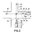
- FIG. 3 A typical accident situation is shown as an example in FIG. 3.
- vehicles 27 and 26 drive in directions 33 and 32, respectively. Both should meet at collision point 34.
- Laser beam receiving devices 30 and 31 are arranged on the front of each vehicle 26 and 27.
- the trucks 39 and 37 are arranged in the extension of the vehicle directions 32 and 33 of the vehicle 26 and 27 beyond the collision point 34.
- the Vehicles 26 and 27 can be guided in directions 35 and 33 to collision point 34.
- guide cables 39 and 40 are laid on or in the carriageway.
- the vehicles 26 and 27 can be guided along the guide cables to the collision point 34 with the aid of the antennas 4.
- all vehicles involved in the course of the accident can each be configured with a laser beam guidance system, or a guidance cable system, or both with combinations of both guidance systems.
Landscapes
- Physics & Mathematics (AREA)
- General Physics & Mathematics (AREA)
- Traffic Control Systems (AREA)
- Aerodynamic Tests, Hydrodynamic Tests, Wind Tunnels, And Water Tanks (AREA)
- Testing Of Devices, Machine Parts, Or Other Structures Thereof (AREA)
- Steering Control In Accordance With Driving Conditions (AREA)
- Electric Propulsion And Braking For Vehicles (AREA)
Applications Claiming Priority (2)
| Application Number | Priority Date | Filing Date | Title |
|---|---|---|---|
| DE4006433A DE4006433C2 (de) | 1990-03-01 | 1990-03-01 | Verfahren und Vorrichtung zum Überprüfen von Wirkungen eines Kraftfahrzeug-Unfalls |
| DE4006433 | 1990-03-01 |
Publications (3)
| Publication Number | Publication Date |
|---|---|
| EP0445671A1 true EP0445671A1 (fr) | 1991-09-11 |
| EP0445671B1 EP0445671B1 (fr) | 1993-06-02 |
| EP0445671B2 EP0445671B2 (fr) | 1998-12-09 |
Family
ID=6401202
Family Applications (1)
| Application Number | Title | Priority Date | Filing Date |
|---|---|---|---|
| EP91103129A Expired - Lifetime EP0445671B2 (fr) | 1990-03-01 | 1991-03-01 | Procédé aussi bien que l'utilisation d'un dispositif d'investigation des effets d'un accident de véhicule |
Country Status (5)
| Country | Link |
|---|---|
| US (1) | US5338206A (fr) |
| EP (1) | EP0445671B2 (fr) |
| JP (1) | JPH0743297B2 (fr) |
| DE (2) | DE4006433C2 (fr) |
| ES (1) | ES2031051T5 (fr) |
Cited By (4)
| Publication number | Priority date | Publication date | Assignee | Title |
|---|---|---|---|---|
| DE19814844A1 (de) * | 1998-04-02 | 1999-10-07 | Volkswagen Ag | Simulationsvorrichtung für Kraftfahrzeugunfälle und Verfahren zum Simulieren von Kraftfahrzeugunfällen |
| DE19826288A1 (de) * | 1998-06-12 | 1999-12-16 | Volkswagen Ag | Simulationsanordnung für Kraftfahrzeugunfälle und Verfahren zur Simulation von Kraftfahrzeugunfällen |
| WO2005071384A1 (fr) * | 2004-01-21 | 2005-08-04 | TÜV SÜD Automotive GmbH | Procede de guidage d'un vehicule le long d'une voie predeterminee, vehicule et systeme pour effectuer des tests en matiere de collision |
| DE19814848B4 (de) * | 1998-04-02 | 2006-05-04 | Volkswagen Ag | Simulationsanordnung für Kraftfahrzeugunfälle und Verfahren zur Simulation von Kraftfahrzeugunfällen |
Families Citing this family (37)
| Publication number | Priority date | Publication date | Assignee | Title |
|---|---|---|---|---|
| CA2100893A1 (fr) * | 1992-08-06 | 1994-02-07 | Michael E. Stickney | Instrument informatise interactif d'enregistrement d'interrogations de temoins |
| NZ259483A (en) * | 1993-01-13 | 1996-11-26 | Roads Corp | Hazard perception test system having sequence of images with subject's ability determined by particular image selected |
| US5483845A (en) * | 1994-09-12 | 1996-01-16 | Morton International, Inc. | Apparatus and method for side impact testing |
| DE19529801C1 (de) * | 1995-08-14 | 1996-07-18 | Ford Werke Ag | Vorrichtung zur Durchführung eines Crashtests bei einem Fahrzeug |
| DE19814846A1 (de) * | 1998-04-02 | 1999-10-07 | Volkswagen Ag | Betätigungsanordnung und Verfahren zur Geschwindigkeits- und/oder Lagebeeinflussung von selbstfahrenden Crashfahrzeugen |
| US6076028A (en) * | 1998-09-29 | 2000-06-13 | Veridian Engineering, Inc. | Method and apparatus for automatic vehicle event detection, characterization and reporting |
| US6522998B1 (en) * | 1998-10-13 | 2003-02-18 | Breed Automotive Technology, Inc. | Sled test apparatus and method for simulating pre-impact crash event |
| DE19909516B4 (de) * | 1999-03-04 | 2008-04-17 | TÜV SÜD Automotive GmbH | Verfahren zum Wahrnehmbarmachen von Meßdaten eines Versuchsablaufs sowie Versuchsdatenerfassungs-Auswertungssystem |
| NL1015517C2 (nl) * | 2000-06-23 | 2001-12-28 | Tno | Stelsel voor het uitvoeren van onderzoek aan intelligente wegvoertuigen. |
| US7058488B2 (en) | 2002-05-03 | 2006-06-06 | Burke E. Porter Machinery Company | Vehicle testing apparatus for measuring a propensity of a vehicle to roll over |
| DE10220613B4 (de) * | 2002-05-08 | 2014-01-16 | Illinois Tool Works Inc. | Verfahren und Vorrichtung zur Durchführung von sogenannten Crashtests |
| CN1771433A (zh) * | 2003-03-28 | 2006-05-10 | Mts系统公司 | 具有动态运动模拟的车辆碰撞模拟器 |
| DE102004003087B4 (de) * | 2004-01-21 | 2006-02-09 | TÜV Automotive GmbH | System zum Durchführen von Crash-Versuchen |
| FR2866114B1 (fr) * | 2004-02-11 | 2006-05-05 | Airbus France | Banc de test mobile pour pneumatiques, et procede de mise en oeuvre d'un tel banc de test |
| DE102007012492B4 (de) * | 2007-03-15 | 2017-11-23 | Illinois Tool Works Inc. | Vorrichtung zur Durchführung von Crash-Versuchen |
| DE102008030612B3 (de) * | 2008-06-27 | 2009-12-31 | Audi Ag | Vorrichtung und Verfahren zum Herbeiführen von kollisionsnahen und kollisionsfreien Situationen zwischen einem Testfahrzeug und einem Kollisionsobjekt und Einrichtung zur Funktionsprüfung eines Fahrerassistenzsystems |
| DE102008041732A1 (de) * | 2008-09-01 | 2010-03-04 | Robert Bosch Gmbh | Fahrwerksprüfungseinrichtung sowie Verfahren zum Prüfen eines Fahrwerks |
| JP5671462B2 (ja) * | 2008-09-12 | 2015-02-18 | エムティーエス システムズ コーポレイション | 風洞において使用するオートパイロットシステム |
| DE102008051233A1 (de) | 2008-10-10 | 2009-05-20 | Daimler Ag | Vorrichtung und Verfahren zum Testen mindestens einer Funktion mindestens eines Fahrerassistenzsystems |
| US8655504B2 (en) * | 2010-04-28 | 2014-02-18 | Hermann Steffan | Safety test carrier controlled by external guidance system |
| US8755999B2 (en) | 2011-07-13 | 2014-06-17 | Dynamic Research Inc. | System and method for testing crash avoidance technologies |
| US8447509B2 (en) | 2011-07-13 | 2013-05-21 | Dynamic Research, Inc. | System and method for testing crash avoidance technologies |
| US8762044B2 (en) * | 2011-07-13 | 2014-06-24 | Dynamic Research, Inc. | System and method for testing crash avoidance technologies |
| US8751143B2 (en) * | 2011-07-13 | 2014-06-10 | Dynamic Research, Inc. | System and method for testing crash avoidance technologies |
| US8428863B2 (en) | 2011-07-13 | 2013-04-23 | Dynamic Research, Inc. | Devices, systems, and methods for testing crash avoidance technologies |
| US8428864B2 (en) | 2011-07-13 | 2013-04-23 | Dynamic Research, Inc. | Devices, systems, and methods for testing crash avoidance technologies |
| US8583358B2 (en) * | 2011-07-13 | 2013-11-12 | Dynamic Research, Inc. | Devices, systems, and methods for testing crash avoidance technologies |
| US8457877B2 (en) | 2011-07-13 | 2013-06-04 | Dynamic Research, Inc. | Devices, systems, and methods for testing crash avoidance technologies |
| US8589062B2 (en) * | 2011-07-13 | 2013-11-19 | Dynamic Research, Inc. | Devices, systems, and methods for testing crash avoidance technologies |
| CN103822790B (zh) * | 2012-11-16 | 2017-11-28 | 哈尔滨飞机工业集团有限责任公司 | 串联舵机试验器 |
| DE102013007498B4 (de) | 2013-04-30 | 2018-05-17 | Audi Ag | Vorrichtung zur Durchführung eines Crashtests eines Kraftfahrzeugs |
| US9412211B2 (en) * | 2014-03-25 | 2016-08-09 | Toyota Motor Engineering & Manufacturing North America, Inc. | System and method for on-vehicle dynamic accident recreation using accident data recording |
| CN108920757A (zh) * | 2018-05-30 | 2018-11-30 | 淮阴工学院 | 一种基于计算机仿真的汽车碰撞事故再现方法 |
| DE202018105162U1 (de) * | 2018-09-10 | 2018-10-18 | Edag Engineering Gmbh | Umfeldsimulationssystem für einen Prüfstand zum Testen von technischen Anlagen oder Maschinen und ein solcher Prüfstand |
| DE102020104329B4 (de) | 2020-02-19 | 2022-08-11 | Audi Aktiengesellschaft | Verfahren, Kalibrierstrecke und System zur Kalibrierung eines Umfeldsensorsystems eines Kraftfahrzeugs |
| JP7465734B2 (ja) * | 2020-06-30 | 2024-04-11 | 株式会社フジタ | 衝突試験車両の制御システム |
| US12140499B2 (en) * | 2022-02-22 | 2024-11-12 | Humaneties Austria GmbH | Overrunable test vehicle |
Family Cites Families (23)
| Publication number | Priority date | Publication date | Assignee | Title |
|---|---|---|---|---|
| JPS4977314A (fr) * | 1972-11-29 | 1974-07-25 | ||
| JPS5424642B2 (fr) * | 1973-07-30 | 1979-08-22 | ||
| JPS50127084A (fr) * | 1974-03-21 | 1975-10-06 | ||
| JPS5112530A (en) * | 1974-07-18 | 1976-01-31 | Kogyo Gijutsuin | Idotaino judohoshiki |
| JPS5327927A (en) * | 1976-08-24 | 1978-03-15 | Kokusai Electric Co Ltd | Circuit for amplifying and detecting automatic steering signal |
| JPS53140729A (en) * | 1977-05-13 | 1978-12-08 | Toyo Umpanki Co Ltd | Automatically guided four-wheel vehicle |
| JPS57143614A (en) * | 1981-02-27 | 1982-09-04 | Komatsu Ltd | Curve run controlling system using laser beam |
| DE3248192A1 (de) * | 1982-08-25 | 1984-03-01 | Roland 7770 Überlingen Heubeck | Vorrichtung zur registrierung bzw. aufzeichnung von daten eines kraftfahrzeuges vor einem unfall |
| US4530056A (en) * | 1982-10-28 | 1985-07-16 | Modular Automation Corp. | Automated guided vehicle system |
| DE3405757A1 (de) * | 1983-02-26 | 1984-10-04 | Edmund 7016 Gerlingen Zottnik | Unfalldatenschreiber |
| JPS59163610A (ja) * | 1983-03-08 | 1984-09-14 | Niigata Eng Co Ltd | 車両の自動操向装置 |
| US4602334A (en) * | 1983-10-31 | 1986-07-22 | Leonard Salesky | Vehicle travel control device |
| JPS6275994A (ja) * | 1985-09-27 | 1987-04-07 | Hitachi Ltd | 複合型磁気バブル装置 |
| JPS62182681A (ja) * | 1986-02-07 | 1987-08-11 | Komatsu Ltd | 車両の自動誘導方法 |
| US4817000A (en) * | 1986-03-10 | 1989-03-28 | Si Handling Systems, Inc. | Automatic guided vehicle system |
| US4982329A (en) * | 1987-06-27 | 1991-01-01 | Shinko Electric Co., Ltd. | Self-contained unmanned vehicle |
| US4947094A (en) * | 1987-07-23 | 1990-08-07 | Battelle Memorial Institute | Optical guidance system for industrial vehicles |
| JPH0430452Y2 (fr) * | 1987-08-06 | 1992-07-22 | ||
| JPS6429556U (fr) * | 1987-08-15 | 1989-02-22 | ||
| US4790402A (en) * | 1987-09-28 | 1988-12-13 | Tennant Company | Automated guided vehicle |
| US4926171A (en) * | 1988-11-21 | 1990-05-15 | Kelley William L | Collision predicting and avoidance device for moving vehicles |
| US5186695A (en) * | 1989-02-03 | 1993-02-16 | Loredan Biomedical, Inc. | Apparatus for controlled exercise and diagnosis of human performance |
| US4992943A (en) * | 1989-02-13 | 1991-02-12 | Mccracken Jack J | Apparatus for detecting and storing motor vehicle impact data |
-
1990
- 1990-03-01 DE DE4006433A patent/DE4006433C2/de not_active Expired - Lifetime
-
1991
- 1991-03-01 EP EP91103129A patent/EP0445671B2/fr not_active Expired - Lifetime
- 1991-03-01 ES ES91103129T patent/ES2031051T5/es not_active Expired - Lifetime
- 1991-03-01 JP JP3059636A patent/JPH0743297B2/ja not_active Expired - Lifetime
- 1991-03-01 DE DE9191103129T patent/DE59100133D1/de not_active Expired - Lifetime
-
1993
- 1993-02-26 US US08/026,623 patent/US5338206A/en not_active Expired - Lifetime
Non-Patent Citations (5)
| Title |
|---|
| ATZ AUTOMOBILTECHNISCHE ZEITSCHRIFT, Band 66, Nr. 7, Juli 1964, Seiten 203-209, Stuttgart, DE; E. FIALA et al.: "Methoden und Einrichtungen f}r Unfallversuche" * |
| ATZ AUTOMOBILTECHNISCHE ZEITSCHRIFT, Band 76, Nr. 9, September 1974, Seiten 277-284, Stuttgart, DE; K.-E. HAILER et al.: "Forschungen und Entwicklungen am Automobil 1974 - Bericht vom XV. FISITA-Kongress in Paris - Teil 1" * |
| ATZ AUTOMOBILTECHNISCHE ZEITSCHRIFT, Band 82, Nr. 10, Oktober 1980, Seiten 507-511, Stuttgart, DE; W. SIEVERT: "Die Aufprall-Versuchsanlage der Bundesanstalt f}r Strassenwesen" * |
| MECHANICAL ENGINEERING, Band 107, Nr. 10, Oktober 1985, Seiten 63-68, New York, US; W.S. REED et al.: "Simulating vehicular collisions" * |
| MESSEN + PR]FEN, Oktober 1979, Seiten 785-790, Wörishofen, DE; M. KRAMER: "Integrierte Datanerfassung und -verarbeitung im Fahrzeugsicherheitsversuch" * |
Cited By (10)
| Publication number | Priority date | Publication date | Assignee | Title |
|---|---|---|---|---|
| DE19814844A1 (de) * | 1998-04-02 | 1999-10-07 | Volkswagen Ag | Simulationsvorrichtung für Kraftfahrzeugunfälle und Verfahren zum Simulieren von Kraftfahrzeugunfällen |
| EP0947818A3 (fr) * | 1998-04-02 | 2000-01-12 | Volkswagen Aktiengesellschaft | Procédé et dispositif de simulation d'accidents de véhicules |
| DE19814844B4 (de) * | 1998-04-02 | 2006-05-04 | Volkswagen Ag | Simulationsvorrichtung für Kraftfahrzeugunfälle und Verfahren zum Simulieren von Kraftfahrzeugunfällen |
| DE19814848B4 (de) * | 1998-04-02 | 2006-05-04 | Volkswagen Ag | Simulationsanordnung für Kraftfahrzeugunfälle und Verfahren zur Simulation von Kraftfahrzeugunfällen |
| DE19826288A1 (de) * | 1998-06-12 | 1999-12-16 | Volkswagen Ag | Simulationsanordnung für Kraftfahrzeugunfälle und Verfahren zur Simulation von Kraftfahrzeugunfällen |
| EP0964239A3 (fr) * | 1998-06-12 | 2000-03-01 | Volkswagen Aktiengesellschaft | Procédé et dispositif de simulation d'accidents de véhicule |
| DE19826288B4 (de) * | 1998-06-12 | 2006-04-27 | Volkswagen Ag | Simulationsanordnung für Kraftfahrzeugunfälle und Verfahren zur Simulation von Kraftfahrzeugunfällen |
| WO2005071384A1 (fr) * | 2004-01-21 | 2005-08-04 | TÜV SÜD Automotive GmbH | Procede de guidage d'un vehicule le long d'une voie predeterminee, vehicule et systeme pour effectuer des tests en matiere de collision |
| CN1918462B (zh) * | 2004-01-21 | 2011-01-12 | 迪福南方汽车有限责任公司 | 沿预定路径导引车辆的方法以及执行碰撞试验的车辆和系统 |
| US8364336B2 (en) | 2004-01-21 | 2013-01-29 | Tuv Sud Automotive Gmbh | Method for guiding a vehicle along a predetermined path as well as vehicle and system for performing crash-tests |
Also Published As
| Publication number | Publication date |
|---|---|
| DE4006433C2 (de) | 2000-01-20 |
| ES2031051T1 (es) | 1992-12-01 |
| ES2031051T5 (es) | 1999-06-01 |
| EP0445671B1 (fr) | 1993-06-02 |
| DE4006433A1 (de) | 1991-09-05 |
| ES2031051T3 (es) | 1993-12-01 |
| EP0445671B2 (fr) | 1998-12-09 |
| JPH0743297B2 (ja) | 1995-05-15 |
| DE59100133D1 (de) | 1993-07-08 |
| US5338206A (en) | 1994-08-16 |
| JPH05223700A (ja) | 1993-08-31 |
Similar Documents
| Publication | Publication Date | Title |
|---|---|---|
| EP0445671B1 (fr) | Procédé et dispositif d'investigation des effets d'un accident de véhicule | |
| EP2795345B1 (fr) | Procédé et dispositif pour la détermination de la position de montage d'un module capteur dans un véhicule et véhicule doté d'un tel dispositif | |
| EP3512744A1 (fr) | Procédé et dispositif permettant de commander un déplacement d'un véhicule et système de commande de déplacement de véhicule | |
| EP1320835B1 (fr) | Procede et dispositif pour detecter des donnees de marche d'une automobile avec une chaine cinematique a commande electronique | |
| DE10012761A1 (de) | Hindernis-Erfassungsverfahren für Fahrzeuge | |
| DE102018001054A1 (de) | Verfahren zum Bewegen einer Fahrzeugkolonne auf Basis einer der Fahrzeugkolonne zugeordneten, vorgebbaren Gesamtbetriebsstrategie | |
| EP0715579B1 (fr) | Systeme de liberation de l'ouverture des portes de vehicules sur rails | |
| DE102019101443A1 (de) | Verfahren zum Steuern einer Fahrzeugkolonne bei einer Notbremsung | |
| EP4323248B1 (fr) | Procédé faire fonctionner un système d'assistance au conducteur et véhicule équipé d'un système d'assistance au conducteur | |
| DE102008054207A1 (de) | Verfahren und Vorrichtung zur Führung eines Fahrzeugs entlang einer vorgebbaren Solltrajektorie | |
| EP3795451B1 (fr) | Procédé de localisation d'un véhicule dans une station destinée à un arrêt du véhicule | |
| WO2005120879A1 (fr) | Procede pour faire fonctionner un systeme d'assistance au conducteur | |
| EP1716403B1 (fr) | Procede de guidage d'un vehicule le long d'une voie predeterminee, vehicule et systeme pour effectuer des tests en matiere de collision | |
| EP1553009B1 (fr) | Assistance pour se garer en créneau | |
| DE19745166A1 (de) | Verfahren zur Sicherheitsüberwachung eines Kraftfahrzeuges | |
| DE102021003867B3 (de) | Verfahren und Vorrichtung zum Betreiben eines Fahrzeugs in einem automatisierten Fahrbetrieb | |
| DE102006026653A1 (de) | Vorrichtung und Verfahren zum Steuern eines Fahrzeugs | |
| DE102022131469A1 (de) | Verfahren zur Kalibration wenigstens einer Detektionsvorrichtung eines Fahrzeugs, bei dem das Fahrzeug wenigstens teilautonom bewegt wird, Detektionsvorrichtung, Fahrerassistenzsystem, Fahrzeug, Kalibrationsanlage und Fertigungsanlage | |
| WO2021078533A1 (fr) | Procédé de fonctionnement de multiples véhicules motorisés, et véhicule motorisé | |
| DE102019215383A1 (de) | Verfahren zur Steuerung einer Bremsanlage und Bremsanlage | |
| DE102004003087B4 (de) | System zum Durchführen von Crash-Versuchen | |
| DE102022100917B4 (de) | Vorrichtungen und Verfahren zum automatisierten Verfahren eines Kraftfahrzeugs | |
| DE102019204338A1 (de) | Adaptive Endanschlagskontrolle des Lenkrades | |
| EP1069021B1 (fr) | Système de commande de train | |
| DE102016214601A1 (de) | Verfahren zur Bestimmung einer Fahrzeugkonstellation einer Gruppe von Kraftfahrzeugen |
Legal Events
| Date | Code | Title | Description |
|---|---|---|---|
| PUAI | Public reference made under article 153(3) epc to a published international application that has entered the european phase |
Free format text: ORIGINAL CODE: 0009012 |
|
| AK | Designated contracting states |
Kind code of ref document: A1 Designated state(s): DE ES FR IT SE |
|
| ITCL | It: translation for ep claims filed |
Representative=s name: ADRIANO DALLA ROSA |
|
| EL | Fr: translation of claims filed | ||
| 17P | Request for examination filed |
Effective date: 19920218 |
|
| 17Q | First examination report despatched |
Effective date: 19920724 |
|
| GRAA | (expected) grant |
Free format text: ORIGINAL CODE: 0009210 |
|
| AK | Designated contracting states |
Kind code of ref document: B1 Designated state(s): DE ES FR IT SE |
|
| RAP2 | Party data changed (patent owner data changed or rights of a patent transferred) |
Owner name: TECHNISCHER UEBERWACHUNGS-VEREIN BAYERN SACHSEN E. |
|
| REF | Corresponds to: |
Ref document number: 59100133 Country of ref document: DE Date of ref document: 19930708 |
|
| ITF | It: translation for a ep patent filed | ||
| ET | Fr: translation filed | ||
| REG | Reference to a national code |
Ref country code: ES Ref legal event code: FG2A Ref document number: 2031051 Country of ref document: ES Kind code of ref document: T3 |
|
| PLBI | Opposition filed |
Free format text: ORIGINAL CODE: 0009260 |
|
| 26 | Opposition filed |
Opponent name: DEKRA AKTIENGESELLSCHAFT Effective date: 19940210 |
|
| EAL | Se: european patent in force in sweden |
Ref document number: 91103129.2 |
|
| PLAB | Opposition data, opponent's data or that of the opponent's representative modified |
Free format text: ORIGINAL CODE: 0009299OPPO |
|
| R26 | Opposition filed (corrected) |
Opponent name: DEKRA AKTIENGESELLSCHAFT Effective date: 19940210 |
|
| PLAW | Interlocutory decision in opposition |
Free format text: ORIGINAL CODE: EPIDOS IDOP |
|
| APAA | Appeal reference recorded |
Free format text: ORIGINAL CODE: EPIDOS REFN |
|
| APAC | Appeal dossier modified |
Free format text: ORIGINAL CODE: EPIDOS NOAPO |
|
| APAC | Appeal dossier modified |
Free format text: ORIGINAL CODE: EPIDOS NOAPO |
|
| APAC | Appeal dossier modified |
Free format text: ORIGINAL CODE: EPIDOS NOAPO |
|
| PLAW | Interlocutory decision in opposition |
Free format text: ORIGINAL CODE: EPIDOS IDOP |
|
| PLAW | Interlocutory decision in opposition |
Free format text: ORIGINAL CODE: EPIDOS IDOP |
|
| PUAH | Patent maintained in amended form |
Free format text: ORIGINAL CODE: 0009272 |
|
| STAA | Information on the status of an ep patent application or granted ep patent |
Free format text: STATUS: PATENT MAINTAINED AS AMENDED |
|
| 27A | Patent maintained in amended form |
Effective date: 19981209 |
|
| AK | Designated contracting states |
Kind code of ref document: B2 Designated state(s): DE ES FR IT SE |
|
| ITF | It: translation for a ep patent filed | ||
| REG | Reference to a national code |
Ref country code: ES Ref legal event code: DC2A Kind code of ref document: T5 Effective date: 19990215 |
|
| APAH | Appeal reference modified |
Free format text: ORIGINAL CODE: EPIDOSCREFNO |
|
| PLAB | Opposition data, opponent's data or that of the opponent's representative modified |
Free format text: ORIGINAL CODE: 0009299OPPO |
|
| PGFP | Annual fee paid to national office [announced via postgrant information from national office to epo] |
Ref country code: ES Payment date: 20100324 Year of fee payment: 20 |
|
| PGFP | Annual fee paid to national office [announced via postgrant information from national office to epo] |
Ref country code: FR Payment date: 20100331 Year of fee payment: 20 |
|
| PGFP | Annual fee paid to national office [announced via postgrant information from national office to epo] |
Ref country code: IT Payment date: 20100327 Year of fee payment: 20 Ref country code: DE Payment date: 20100330 Year of fee payment: 20 |
|
| PGFP | Annual fee paid to national office [announced via postgrant information from national office to epo] |
Ref country code: SE Payment date: 20100324 Year of fee payment: 20 |
|
| REG | Reference to a national code |
Ref country code: DE Ref legal event code: R071 Ref document number: 59100133 Country of ref document: DE |
|
| REG | Reference to a national code |
Ref country code: SE Ref legal event code: EUG |
|
| REG | Reference to a national code |
Ref country code: ES Ref legal event code: FD2A Effective date: 20120510 |
|
| PG25 | Lapsed in a contracting state [announced via postgrant information from national office to epo] |
Ref country code: ES Free format text: LAPSE BECAUSE OF EXPIRATION OF PROTECTION Effective date: 20110302 |
|
| PG25 | Lapsed in a contracting state [announced via postgrant information from national office to epo] |
Ref country code: DE Free format text: LAPSE BECAUSE OF EXPIRATION OF PROTECTION Effective date: 20110301 |