EP0445848A2 - Steuerungssystem zur Steuerung eines Gleichstrommotors, der den Betriebszustand einer Brennkraftmaschine steuert - Google Patents
Steuerungssystem zur Steuerung eines Gleichstrommotors, der den Betriebszustand einer Brennkraftmaschine steuert Download PDFInfo
- Publication number
- EP0445848A2 EP0445848A2 EP91107702A EP91107702A EP0445848A2 EP 0445848 A2 EP0445848 A2 EP 0445848A2 EP 91107702 A EP91107702 A EP 91107702A EP 91107702 A EP91107702 A EP 91107702A EP 0445848 A2 EP0445848 A2 EP 0445848A2
- Authority
- EP
- European Patent Office
- Prior art keywords
- control motor
- engine
- control
- controlling
- operation condition
- Prior art date
- Legal status (The legal status is an assumption and is not a legal conclusion. Google has not performed a legal analysis and makes no representation as to the accuracy of the status listed.)
- Granted
Links
Images

Classifications
-
- F—MECHANICAL ENGINEERING; LIGHTING; HEATING; WEAPONS; BLASTING
- F02—COMBUSTION ENGINES; HOT-GAS OR COMBUSTION-PRODUCT ENGINE PLANTS
- F02D—CONTROLLING COMBUSTION ENGINES
- F02D9/00—Controlling engines by throttling air or fuel-and-air induction conduits or exhaust conduits
- F02D9/04—Controlling engines by throttling air or fuel-and-air induction conduits or exhaust conduits concerning exhaust conduits
-
- F—MECHANICAL ENGINEERING; LIGHTING; HEATING; WEAPONS; BLASTING
- F02—COMBUSTION ENGINES; HOT-GAS OR COMBUSTION-PRODUCT ENGINE PLANTS
- F02D—CONTROLLING COMBUSTION ENGINES
- F02D35/00—Controlling engines, dependent on conditions exterior or interior to engines, not otherwise provided for
- F02D35/0007—Controlling engines, dependent on conditions exterior or interior to engines, not otherwise provided for using electrical feedback
Definitions
- the present invention relates generally to a control system for controlling operation condition of an engine for a motor vehicle, and particularly to a control system for controlling a DC control motor which controls operation of an internal combustion engine to follow-up a target value varying continuously depending on the operation condition of the engine.
- Japanese Patent Laid-Open Publication No. 126222/1987 teaches a system wherein an exhaust gas control valve is disposed at a vicinity of the downstream end of the exhaust pipe, and the exhaust gas control valve is fully opened to utilize the kinetic effect of the exhaust system at the maximum extent so as to increase the output of the engine when the engine is operated within its high speed range.
- the exhaust gas control valve is closed to about one half of the full open angle, when the engine is operated within its medium speed range, to prevent formation of trough of torque due to the reverse effect of kinetics in the exhaust system.
- Another proposal has been made to change the effective length of the exhaust pipe by the provision of control valves on the connection pipes connecting the plural exhaust pipes and by opening or closing the control valves depending on the change in rotation speed of the engine.
- An object of this invention is to provide a control system for controlling a DC control motor which controls an internal combustion engine to follow-up a target value varying continuously depending on the operation condition of the engine by controlling the current flowing through the DC control motor by pulse width modulation, so as to solve the aforementioned problem that the control valve cannot be moved by the DC control motor in the event where the difference between the target value and the up-to-date value is relatively small and the duty ratio is also small and where carbon or dust sticks to the control valve to increase the torque for actuating the control valve.
- a control system for controlling a DC control motor which controls an internal combustion engine to follow-up a target value based on the operation condition of the engine through pulse width modulation, wherein the speed of the DC control motor is monitored and the duty ratio of the current flowing through the DC controllmotoris increased when the changing rate of the up-to-date value is less than the programmed rate. It is thus possible to ensure actuation of the DC control motor even if the difference between the target value and the up-to-date value is small or the loading applied on the DC control motor is high.
- the object of this invention is achieved by the provision of a control system for controlling a DC control motor which controls an internal combustion engine to follow-up a target value varying continuously depending on the operation condition of said engine, said DC control motor being controlled through pulse width modulation, said control system comprising: means for detecting the operation condition of said engine; processor means for calculating and setting a target value depending on said operation condition of said engine; detector means for detecting the up-to-date value of said DC control motor; discriminator means for discriminating a difference between said target value and said up-to-date value to supply an output signal for changing the duty ratio of the current flowing through said DC control motor depending on said difference; a driver for energizing said DC control motor in response to said output signal from said discriminator means; and monitor means for monitoring the changing rate of said up-to-date value and for increasing said duty ratio when said changing rate of said up-to-date value is less than a programmed rate.
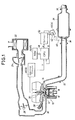
- a four-cycle internal combustion engine is denoted by 10, and has an intake valve 12 and an exhaust valve 14 which are opened and closed by valve actuating means (not shown) at predetermined timing.
- the engine 10 is further provided with a cylinder 16, a piston 18 which cooperates with the cylinder 16, and an ignition plug 20 which ignites the compressed fuel-air mixture in the cylinder 16.
- the intake system of the engine 10 includes an air cleaner 22, an air flow meter 24, a throttle valve 26 and a fuel injection valve 28. Air is sucked through the air cleaner 22 at a flow rate determined by the rotation speed of the crank shaft (not shown) of the engine 10 and the open angle of the throttle valve 26.
- the flow rate of the sucked air is measured by the air flow meter 24.
- the optimal quantity of fuel corresponding to the sucked air quantity and adapted to the operation conditions is calculated by a computer (not shown) and supplied through a fuel injection valve 28 which injects the supplied fuel into the intake pipe 30.
- the exhaust system includes a first exhaust pipe 32 having one end opened and closed by the exhaust valve 14, an expansion chamber 34 connected with the other or downstream end of the first exhaust pipe 32, and a second exhaust pipe 36 connected to the downstream end of the expansion chamber 34.
- a control valve a butterfly valve 38 in the illustrated embodiment, is disposed at a vicinity of the downstream end of the first exhaust pipe 32 to control the flow of exhaust gases.
- the control valve 38 is opened and closed by an actuator, a DC servomotor 42 in the illustrated embodiment, through a wire 40.
- the servomotor 42 is fitted with a potentiometer 44 which serves as the means A for detecting the up-to-date open angle ⁇ (i.e. the up-to-date value) of the control valve 38 by detecting the angular position of the servomotor 42.
- the ignition plug 20 is connected to an ignition circuit 46 which is utilized as the means B for detecting the operation condition of the engine 10.
- the rotation speed n of the engine 10 is detected from the ignition circuit 46.
- a central processor unit (CPU) or digital microprocessor is generally denoted by 48 and includes a processor C for calculating and setting the target value, a discriminator D , and monitor means E ' for monitoring the rotation speed of the actuator (servomotor 42).
- the processor C reads-out the data corresponding to the rotation speed n from a read-only memory (ROM) which stores a control map, and calculates the target open angle ⁇ 0 of the control valve 38.
- the ROM 50 is shown as the comparator means F for comparing with the control map in Fig. 2.
- the discriminator D discriminates the difference between the target open angle ⁇ 0 and the up-to-date open angle ⁇ to generate a control signal ⁇ which is fed to a driver 52.
- the signal ⁇ is a signal for controlling the electric current flowing through the servomotor 42, for example, by the pulse width modulating system
- the duty ratio of the current flowing through the servomotor 42 is changed depending on the difference between ⁇ 0 and ⁇ , and also depending on the change in loading applied on the servomotor 42.
- the flow direction of the electric current is determined so that the open angle of the control valve 38 is increased when ⁇ is smaller than ⁇ 0 and the open angle of the control valve 38 is decreased when ⁇ is larger than ⁇ 0 .
- the rotation speed monitor means E ' monitors the rotation speed of the servomotor. Since the rotation speed of the actuator or servomotor is determined depending to the load applied thereto, a signal is fed to the discriminator means D to increase the duty ratio stepwisely when the rotation speed is less than a programmed level.
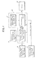
- the illustrated embodiment operates to repeat the operation sequence including the sub-routine shown in Fig. 3 within every predetermined time period, for example within 2 milliseconds.
- the duty ratio of the current may be changed stepwisely to take a value which is shifted from one to four times of 2 milliseconds.
- the duty ratio may be selected stepwisely from the four ratios D(1), D(2), D(3) and D(4).
- D(1) means that the duty ratio is 25%
- D(2) means that the duty ratio is 50%
- D(3) means that the duty ratio is 75%
- D(4) means that the duty ratio is 100%.
- CPU 48 repeats the sub-routine of Fig. 3 within every 2 millisecond cycle.
- CPU 48 discriminates whether the target value ⁇ is changed or not (Step 200). For this purpose, the target value ⁇ 0 at time T is compared with the target value ⁇ 0 (T - t) at the time before the time T by t . If the change in target value ⁇ 0 is smaller than a predetermined range, it is judged that the target value is not changed.
- This operation is the one for learning the rotation speed of the servomotor 42, since the movement within a predetermined time period is obtained thereby, the movement being represented by the following equation of: ⁇ H ⁇ (T+ ⁇ 0 )-H ⁇ (T) ⁇ / ⁇ 0
- Step 210 If the absolute value of the rotation speed is less than a programmed value a/ ⁇ 0 , it is judged that the load applied on the servomotor 42 is excessively high to raise the duty ratio of the current flowing through the servomotor 42 by one step (Step 210). For example, the duty ratio is raised from D(1) to D(2), from D(2) to D(3), and from D(3) to D(4), respectively. If the duty ratio D before this step 210 is D(4), the operation is continued at the duty ratio D(4) since no higher duty ratio is not present (Steps 212 and 214).
- the duty ratio is raised stepwisely one by one if the rotation speed of the servomotor 42 is less than the pre-set level, the current flowing through the servomotor 42 is increased to ensure the actuation thereof.
- the present invention is applied for the actuation of the exhaust gas control valve 38 disposed at the downstream end of the exhaust pipe 32 so that the valve 38 is opened when the engine is operated within its high speed range and the valve 38 is closed when the engine is operated within its medium speed range to prevent formation of trough of torque.
- the present invention may be applied to control other control valves.
- a control valve for controlling the effective pipe length of an intake pipe may be controlled within the scope and spirit of this invention.
Landscapes
- Engineering & Computer Science (AREA)
- Chemical & Material Sciences (AREA)
- Combustion & Propulsion (AREA)
- Mechanical Engineering (AREA)
- General Engineering & Computer Science (AREA)
- Control Of Throttle Valves Provided In The Intake System Or In The Exhaust System (AREA)
- Combined Controls Of Internal Combustion Engines (AREA)
- Electrical Control Of Air Or Fuel Supplied To Internal-Combustion Engine (AREA)
Applications Claiming Priority (3)
| Application Number | Priority Date | Filing Date | Title |
|---|---|---|---|
| JP45287/87 | 1987-03-02 | ||
| JP62045287A JP2614443B2 (ja) | 1987-03-02 | 1987-03-02 | 車輛の制御用モータの制御装置 |
| EP88301766A EP0281358B1 (de) | 1987-03-02 | 1988-03-01 | Steuerungssystem zur Steuerung eines Gleichstrommotors, der den Betriebszustand einer Brennkraftmaschine steuert |
Related Parent Applications (1)
| Application Number | Title | Priority Date | Filing Date |
|---|---|---|---|
| EP88301766.7 Division | 1988-03-01 |
Publications (3)
| Publication Number | Publication Date |
|---|---|
| EP0445848A2 true EP0445848A2 (de) | 1991-09-11 |
| EP0445848A3 EP0445848A3 (en) | 1991-12-18 |
| EP0445848B1 EP0445848B1 (de) | 1994-12-28 |
Family
ID=12715097
Family Applications (1)
| Application Number | Title | Priority Date | Filing Date |
|---|---|---|---|
| EP91107702A Expired - Lifetime EP0445848B1 (de) | 1987-03-02 | 1988-03-01 | Steuerungssystem zur Steuerung eines Gleichstrommotors, der den Betriebszustand einer Brennkraftmaschine steuert |
Country Status (3)
| Country | Link |
|---|---|
| EP (1) | EP0445848B1 (de) |
| JP (1) | JP2614443B2 (de) |
| DE (1) | DE3852653T2 (de) |
Families Citing this family (2)
| Publication number | Priority date | Publication date | Assignee | Title |
|---|---|---|---|---|
| JP4977903B2 (ja) * | 2007-12-26 | 2012-07-18 | 本田技研工業株式会社 | 排気バルブ制御装置 |
| JP2010223035A (ja) * | 2009-03-23 | 2010-10-07 | Mitsuba Corp | ターボチャージャーの可変ノズル制御装置 |
Family Cites Families (8)
| Publication number | Priority date | Publication date | Assignee | Title |
|---|---|---|---|---|
| JPS5743596A (en) * | 1980-08-29 | 1982-03-11 | Honda Motor Co Ltd | Drive control device for pulse motor |
| JPS57110743A (en) * | 1980-12-26 | 1982-07-09 | Fuji Heavy Ind Ltd | Engine speed controlling device |
| JPS603704A (ja) * | 1983-06-22 | 1985-01-10 | Honda Motor Co Ltd | 電磁弁制御方法 |
| JPS60131004A (ja) * | 1983-12-20 | 1985-07-12 | Suzuki Motor Co Ltd | 電動車の速度制御装置 |
| DE3510173C2 (de) * | 1984-08-16 | 1994-02-24 | Bosch Gmbh Robert | Überwachungseinrichtung für eine elektronisch gesteuerte Drosselklappe in einem Kraftfahrzeug |
| JPS61152933A (ja) * | 1984-12-27 | 1986-07-11 | Nissan Motor Co Ltd | エンジンのスロツトル制御装置 |
| JPS61232365A (ja) * | 1985-04-08 | 1986-10-16 | Mitsubishi Electric Corp | 位置制御装置 |
| GB2175643B (en) * | 1985-05-24 | 1989-08-31 | Orbital Eng Pty | Improvements relating to controlling emissions from two stroke engines |
-
1987
- 1987-03-02 JP JP62045287A patent/JP2614443B2/ja not_active Expired - Fee Related
-
1988
- 1988-03-01 EP EP91107702A patent/EP0445848B1/de not_active Expired - Lifetime
- 1988-03-01 DE DE19883852653 patent/DE3852653T2/de not_active Expired - Lifetime
Also Published As
| Publication number | Publication date |
|---|---|
| DE3852653D1 (de) | 1995-02-09 |
| JPS63212752A (ja) | 1988-09-05 |
| EP0445848B1 (de) | 1994-12-28 |
| EP0445848A3 (en) | 1991-12-18 |
| JP2614443B2 (ja) | 1997-05-28 |
| DE3852653T2 (de) | 1995-07-13 |
Similar Documents
| Publication | Publication Date | Title |
|---|---|---|
| US5881552A (en) | Control system for internal combustion engines and control system for vehicles | |
| US4583176A (en) | Method for detecting abnormality in the functioning of an electronic control system | |
| US5201173A (en) | Catalyst temperature control system for internal combustion engines | |
| US5140810A (en) | Method of detecting failure in a secondary air supply system for internal combustion engines | |
| US4491115A (en) | Method for controlling fuel supply to an internal combustion engine at deceleration | |
| EP1548255B1 (de) | Steuervorrichtung für eine Brennkraftmaschine | |
| US5698779A (en) | Apparatus for detecting intake air quantity of internal combustion engine having mechanism for continuously varying valve timing | |
| US5443547A (en) | Exhaust gas recirculation system | |
| US4933863A (en) | Control systems for internal combustion engines | |
| US6076502A (en) | Exhaust gas recirculation control system for internal combustion engines | |
| JP2964210B2 (ja) | 筒内圧センサの診断装置 | |
| US5333446A (en) | Diagnostic system for a secondary air supplier in an engine | |
| US5129228A (en) | Electronic engine control system | |
| US4696277A (en) | Engine alarm system | |
| US4450680A (en) | Air/fuel ratio control system for internal combustion engines, having secondary air supply control | |
| US6173694B1 (en) | Method and apparatus for controlling fuel injection in an in-cylinder type internal combustion engine | |
| US4718014A (en) | Apparatus for controlling ignition timing in an internal combustion engine | |
| US4771755A (en) | Abnormality detecting method for air-fuel ratio control system for internal combustion engines | |
| US4827718A (en) | Control system for controlling actuator to control operation of internal combustion engine | |
| EP0281358B1 (de) | Steuerungssystem zur Steuerung eines Gleichstrommotors, der den Betriebszustand einer Brennkraftmaschine steuert | |
| EP0445848B1 (de) | Steuerungssystem zur Steuerung eines Gleichstrommotors, der den Betriebszustand einer Brennkraftmaschine steuert | |
| EP0646709B1 (de) | Luft-Brennstoff-Verhältnisregelvorrichtung für Brennkraftmaschinen | |
| EP0162353B1 (de) | Ansaugsystem für eine Brennkraftmaschine | |
| US4407243A (en) | Air/fuel ratio control system having function of controlling supply of secondary air into intake pipe of internal combustion engine | |
| EP0787897A2 (de) | Vorrichtung zur Steuerung der Ansaugluft einer Brennkraftmaschine |
Legal Events
| Date | Code | Title | Description |
|---|---|---|---|
| PUAI | Public reference made under article 153(3) epc to a published international application that has entered the european phase |
Free format text: ORIGINAL CODE: 0009012 |
|
| 17P | Request for examination filed |
Effective date: 19910513 |
|
| AC | Divisional application: reference to earlier application |
Ref document number: 281358 Country of ref document: EP |
|
| AK | Designated contracting states |
Kind code of ref document: A2 Designated state(s): DE ES FR GB IT |
|
| PUAL | Search report despatched |
Free format text: ORIGINAL CODE: 0009013 |
|
| AK | Designated contracting states |
Kind code of ref document: A3 Designated state(s): DE ES FR GB IT |
|
| 17Q | First examination report despatched |
Effective date: 19930514 |
|
| GRAA | (expected) grant |
Free format text: ORIGINAL CODE: 0009210 |
|
| AC | Divisional application: reference to earlier application |
Ref document number: 281358 Country of ref document: EP |
|
| PG25 | Lapsed in a contracting state [announced via postgrant information from national office to epo] |
Ref country code: IT Free format text: LAPSE BECAUSE OF FAILURE TO SUBMIT A TRANSLATION OF THE DESCRIPTION OR TO PAY THE FEE WITHIN THE PRE;WARNING: LAPSES OF ITALIAN PATENTS WITH EFFECTIVE DATE BEFORE 2007 MAY HAVE OCCURRED AT ANY TIME BEFORE 2007. THE CORRECT EFFECTIVE DATE MAY BE DIFFERENT FROM THE ONE RECORDED.SCRIBED TIME-LIMIT Effective date: 19941228 Ref country code: ES Free format text: THE PATENT HAS BEEN ANNULLED BY A DECISION OF A NATIONAL AUTHORITY Effective date: 19941228 Ref country code: FR Effective date: 19941228 |
|
| REF | Corresponds to: |
Ref document number: 3852653 Country of ref document: DE Date of ref document: 19950209 |
|
| EN | Fr: translation not filed | ||
| PLBE | No opposition filed within time limit |
Free format text: ORIGINAL CODE: 0009261 |
|
| STAA | Information on the status of an ep patent application or granted ep patent |
Free format text: STATUS: NO OPPOSITION FILED WITHIN TIME LIMIT |
|
| 26N | No opposition filed | ||
| REG | Reference to a national code |
Ref country code: GB Ref legal event code: IF02 |
|
| PGFP | Annual fee paid to national office [announced via postgrant information from national office to epo] |
Ref country code: DE Payment date: 20070222 Year of fee payment: 20 |
|
| PGFP | Annual fee paid to national office [announced via postgrant information from national office to epo] |
Ref country code: GB Payment date: 20070228 Year of fee payment: 20 |
|
| REG | Reference to a national code |
Ref country code: GB Ref legal event code: PE20 |
|
| PG25 | Lapsed in a contracting state [announced via postgrant information from national office to epo] |
Ref country code: GB Free format text: LAPSE BECAUSE OF EXPIRATION OF PROTECTION Effective date: 20080229 |