EP0445902A1 - Conduite isolée thermiquement - Google Patents
Conduite isolée thermiquement Download PDFInfo
- Publication number
- EP0445902A1 EP0445902A1 EP91250058A EP91250058A EP0445902A1 EP 0445902 A1 EP0445902 A1 EP 0445902A1 EP 91250058 A EP91250058 A EP 91250058A EP 91250058 A EP91250058 A EP 91250058A EP 0445902 A1 EP0445902 A1 EP 0445902A1
- Authority
- EP
- European Patent Office
- Prior art keywords
- connectors
- insulated conduit
- heat
- inner tube
- connector
- Prior art date
- Legal status (The legal status is an assumption and is not a legal conclusion. Google has not performed a legal analysis and makes no representation as to the accuracy of the status listed.)
- Ceased
Links
- 238000009413 insulation Methods 0.000 claims abstract description 10
- 230000001788 irregular Effects 0.000 abstract description 2
- 241001484259 Lacuna Species 0.000 abstract 1
- 238000003466 welding Methods 0.000 description 8
- 238000004519 manufacturing process Methods 0.000 description 5
- 238000010276 construction Methods 0.000 description 2
- 238000000034 method Methods 0.000 description 2
- RYGMFSIKBFXOCR-UHFFFAOYSA-N Copper Chemical compound [Cu] RYGMFSIKBFXOCR-UHFFFAOYSA-N 0.000 description 1
- 238000010793 Steam injection (oil industry) Methods 0.000 description 1
- 229910052802 copper Inorganic materials 0.000 description 1
- 239000010949 copper Substances 0.000 description 1
- 230000006735 deficit Effects 0.000 description 1
- 239000012530 fluid Substances 0.000 description 1
- 238000009434 installation Methods 0.000 description 1
- 238000003754 machining Methods 0.000 description 1
- 239000011435 rock Substances 0.000 description 1
- 238000005096 rolling process Methods 0.000 description 1
- 238000010079 rubber tapping Methods 0.000 description 1
Images
Classifications
-
- F—MECHANICAL ENGINEERING; LIGHTING; HEATING; WEAPONS; BLASTING
- F16—ENGINEERING ELEMENTS AND UNITS; GENERAL MEASURES FOR PRODUCING AND MAINTAINING EFFECTIVE FUNCTIONING OF MACHINES OR INSTALLATIONS; THERMAL INSULATION IN GENERAL
- F16L—PIPES; JOINTS OR FITTINGS FOR PIPES; SUPPORTS FOR PIPES, CABLES OR PROTECTIVE TUBING; MEANS FOR THERMAL INSULATION IN GENERAL
- F16L59/00—Thermal insulation in general
- F16L59/14—Arrangements for the insulation of pipes or pipe systems
- F16L59/143—Pre-insulated pipes
-
- F—MECHANICAL ENGINEERING; LIGHTING; HEATING; WEAPONS; BLASTING
- F16—ENGINEERING ELEMENTS AND UNITS; GENERAL MEASURES FOR PRODUCING AND MAINTAINING EFFECTIVE FUNCTIONING OF MACHINES OR INSTALLATIONS; THERMAL INSULATION IN GENERAL
- F16L—PIPES; JOINTS OR FITTINGS FOR PIPES; SUPPORTS FOR PIPES, CABLES OR PROTECTIVE TUBING; MEANS FOR THERMAL INSULATION IN GENERAL
- F16L59/00—Thermal insulation in general
- F16L59/14—Arrangements for the insulation of pipes or pipe systems
- F16L59/16—Arrangements specially adapted to local requirements at flanges, junctions, valves or the like
- F16L59/18—Arrangements specially adapted to local requirements at flanges, junctions, valves or the like adapted for joints
Definitions
- the invention relates to a heat-insulated conduit according to the preamble of the main claim.
- the connectors are mechanically machined thick-walled hollow bodies, each having a threaded section at the ends, the threaded section to be screwed to the inner tube as a socket element and the threaded section to be connected to the next insulated conduit either as a pin or is designed as a sleeve element.
- thermal insulation is arranged over the entire length, which comprises an outer tube which is fixedly connected to the connectors and is penetrated by centering rings which are arranged at non-uniform intervals over the length.
- a disadvantage of this construction is that the manufacture of the connectors, each having two threaded sections, is expensive and the length of the outer tube has to be adjusted when the thread on the inner tube is cut.
- the object of the invention is to provide an improved heat-insulated conduit with which the disadvantages described are avoided.
- the proposal according to the invention is based on designing the connector so that it has a thread-free section on the inward end, which can be connected to the inner tube via a weld seam.
- the type of welded connection can be different, preferably a friction weld is proposed.
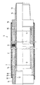
- the heat-insulated conduit 1 is shown in a longitudinal section.
- the lower half shows the non-prestressed state and the upper half shows the prestressed state.
- the heat-insulated conduit 1 consists of a smooth-ended inner tube 2, which is connected at the ends to the connectors 5, 6 via a friction welding seam 3, 4.
- the connectors 5, 6 have a thread-free section 14, 15 on the inward end.
- thermal insulation 7 is arranged, which is completely enclosed by an outer tube 8.
- centering rings 9 (only one shown here) distributed over the length are arranged at irregular intervals.
- the outer tube 8 is firmly connected to the connectors 5, 6 via a weld seam 10, 11.
- the connectors 5, 6 On the end facing away from the inner tube 2, the connectors 5, 6 have a threaded section 12, 13, which is designed once as a sleeve element 12 and once as a pin element 13.
- this type of connection is referred to as an integral connection.
- the step 16 in the outer diameter range of the connector 5 designed as a sleeve part can be omitted. Accordingly, the thickened part of the connector 6 designed as a pin part would also be reduced.
- the individual work steps that are required for the production of such a conduit 1 according to the invention are listed below.
- the hot-finished inner tube 2 produced by a conventional rolling process is tapped at the ends with a smooth end and fed to the friction welding system.
- the two connectors 5, 6 are produced from thick-walled pieces of pipe by mechanical processing.
- the connectors 5, 6 are connected to the smooth-ended inner tube 2.
- the welding bears that arise during the friction welding are eliminated by mechanical internal and external machining.
- the heat insulation 7 is applied to the outside of the inner tube 2 and the separately produced outer tube 8 is pushed over the heat insulation 7.
Landscapes
- Engineering & Computer Science (AREA)
- General Engineering & Computer Science (AREA)
- Mechanical Engineering (AREA)
- Thermal Insulation (AREA)
Applications Claiming Priority (4)
| Application Number | Priority Date | Filing Date | Title |
|---|---|---|---|
| DE4008019 | 1990-03-09 | ||
| DE4008019 | 1990-03-09 | ||
| DE9101169U | 1991-01-31 | ||
| DE9101169U DE9101169U1 (de) | 1990-03-09 | 1991-01-31 | Wärmeisoliertes Leitungsrohr |
Publications (1)
| Publication Number | Publication Date |
|---|---|
| EP0445902A1 true EP0445902A1 (fr) | 1991-09-11 |
Family
ID=25891097
Family Applications (1)
| Application Number | Title | Priority Date | Filing Date |
|---|---|---|---|
| EP91250058A Ceased EP0445902A1 (fr) | 1990-03-09 | 1991-03-06 | Conduite isolée thermiquement |
Country Status (3)
| Country | Link |
|---|---|
| EP (1) | EP0445902A1 (fr) |
| DE (1) | DE9101169U1 (fr) |
| NO (1) | NO910905L (fr) |
Cited By (4)
| Publication number | Priority date | Publication date | Assignee | Title |
|---|---|---|---|---|
| FR2693252A1 (fr) * | 1992-07-01 | 1994-01-07 | Orbey Plastiques Ind | Dispositif pour adapter un élément chaud sur un corps creux en matière thermoplastique comportant au moins une arrivée de fluide froid, et corps creux comportant un tel dispositif. |
| FR2844008A1 (fr) * | 2002-08-29 | 2004-03-05 | Siemens Vdo Automotive Inc | Assemblage de tubes egr a double etancheite |
| US7011115B1 (en) | 1999-05-27 | 2006-03-14 | Saipem, S.P.A. | Insulated pipe structure and methods of making such structures |
| GB2542271A (en) * | 2015-09-08 | 2017-03-15 | Itp Sa | A method of commissioning a subsea hydrocarbon well |
Citations (4)
| Publication number | Priority date | Publication date | Assignee | Title |
|---|---|---|---|---|
| US3574357A (en) * | 1969-02-27 | 1971-04-13 | Grupul Ind Pentru Foray Si Ext | Thermal insulating tubing |
| DE3215201A1 (de) * | 1981-04-27 | 1982-11-11 | General Electric Co., Schenectady, N.Y. | Isolierte hochtemperatur-verrohrungsbaugruppe |
| DE3318045C1 (de) * | 1983-05-18 | 1984-12-13 | BEB Gewerkschaften Brigitta und Elwerath Betriebsführungsgesellschaft mbH, 3000 Hannover | Lösbare, dichte Schraubverbindung für Verbundrohr-Leitungsstücke zum Transport erwärmter Medien |
| EP0190092A2 (fr) * | 1985-01-31 | 1986-08-06 | MANNESMANN Aktiengesellschaft | Tube pour l'exploitation pétrolière |
-
1991
- 1991-01-31 DE DE9101169U patent/DE9101169U1/de not_active Expired - Lifetime
- 1991-03-06 EP EP91250058A patent/EP0445902A1/fr not_active Ceased
- 1991-03-07 NO NO91910905A patent/NO910905L/no unknown
Patent Citations (4)
| Publication number | Priority date | Publication date | Assignee | Title |
|---|---|---|---|---|
| US3574357A (en) * | 1969-02-27 | 1971-04-13 | Grupul Ind Pentru Foray Si Ext | Thermal insulating tubing |
| DE3215201A1 (de) * | 1981-04-27 | 1982-11-11 | General Electric Co., Schenectady, N.Y. | Isolierte hochtemperatur-verrohrungsbaugruppe |
| DE3318045C1 (de) * | 1983-05-18 | 1984-12-13 | BEB Gewerkschaften Brigitta und Elwerath Betriebsführungsgesellschaft mbH, 3000 Hannover | Lösbare, dichte Schraubverbindung für Verbundrohr-Leitungsstücke zum Transport erwärmter Medien |
| EP0190092A2 (fr) * | 1985-01-31 | 1986-08-06 | MANNESMANN Aktiengesellschaft | Tube pour l'exploitation pétrolière |
Cited By (6)
| Publication number | Priority date | Publication date | Assignee | Title |
|---|---|---|---|---|
| FR2693252A1 (fr) * | 1992-07-01 | 1994-01-07 | Orbey Plastiques Ind | Dispositif pour adapter un élément chaud sur un corps creux en matière thermoplastique comportant au moins une arrivée de fluide froid, et corps creux comportant un tel dispositif. |
| US5542711A (en) * | 1992-07-01 | 1996-08-06 | Orbey Plastiques And Industries | Device for fitting a hot element to a hollow body made of thermoplastic including at least one cold fluid inlet, and hollow body including such a device |
| US7011115B1 (en) | 1999-05-27 | 2006-03-14 | Saipem, S.P.A. | Insulated pipe structure and methods of making such structures |
| FR2844008A1 (fr) * | 2002-08-29 | 2004-03-05 | Siemens Vdo Automotive Inc | Assemblage de tubes egr a double etancheite |
| GB2542271A (en) * | 2015-09-08 | 2017-03-15 | Itp Sa | A method of commissioning a subsea hydrocarbon well |
| GB2542271B (en) * | 2015-09-08 | 2021-01-27 | Itp Sa | A method of commissioning a subsea hydrocarbon well |
Also Published As
| Publication number | Publication date |
|---|---|
| NO910905L (no) | 1991-09-10 |
| DE9101169U1 (de) | 1991-04-25 |
| NO910905D0 (no) | 1991-03-07 |
Similar Documents
| Publication | Publication Date | Title |
|---|---|---|
| DE19831626C2 (de) | Rohrverbindung mit einem einem Rohrende angeformten Verbindungsabschnitt | |
| DE3834080C2 (fr) | ||
| DE2927716A1 (de) | Fluid-verbindungsstueck | |
| CH663832A5 (de) | Rohrschelle zum verbinden zweier rohrenden. | |
| DE3515169A1 (de) | Rohrverbindung zum verbinden von zwei mit gewinden versehenen rohrenden | |
| EP0445902A1 (fr) | Conduite isolée thermiquement | |
| DE3315819A1 (de) | Rohrleitung (pipeline) zur foerderung von insbesondere aggresiven medien und verfahren zum zusammensetzen bzw. verlegen der rohrleitung | |
| EP0222855B1 (fr) | Procede de fabrication d'un embout pour raccords filetes ou a emboitement soumis a des charges hydrauliques | |
| CH362890A (de) | Befestigung eines metallischen Wellrohres in einem metallischen Anschlussstück und Verfahren zur Herstellung der Befestigung | |
| EP3982025B9 (fr) | Robinetterie de raccordement, conduite de fluide surmoulée pourvue de conduite de fluide tubulaire et/ou en forme de tuyau et d'une telle robinetterie de raccordement, ainsi que procédé de production d'une telle conduite de fluide surmoulée | |
| EP0081667A1 (fr) | Tuyaux posable sans compensateurs pour système de chauffage à grande distance | |
| DE4136349C2 (de) | Schweißvorrichtung für Kunststoffrohre | |
| DE3233983A1 (de) | Verfahren und vorrichtung zum fortlaufenden ummanteln von rohren aus kunststoff mit einem schutzmantel | |
| DE824506C (de) | Kabelverbindung | |
| DE19832288B4 (de) | Verfahren zur Herstellung eines Verbindungselementes | |
| DE944481C (de) | Rotary-Bohrgestaengeverbindung | |
| DE4432199A1 (de) | Verfahren zum Verbinden eines Kunststoff-Rohres mit einer Kunststoff-Muffe | |
| EP4012240B1 (fr) | Tuyau de dérivation pour le raccordement du capteur | |
| DE3316482A1 (de) | Verfahren zum verlegen eines aus einzelnen waermeisolierten leitungsrohren bestehenden rohrstranges | |
| DE2054337B2 (de) | Halterung fuer ein regelstab-fuehrungsrohr | |
| DE19634681C2 (de) | Vorrichtung für eine Rohrschweißanlage | |
| EP0390057A1 (fr) | Ligne de tubes approprié pour le remplacement d'une pièce de tube, méthode de remplacement de cette pièce de tube et ligne de tubes produite avec cette méthode | |
| DE2426730C3 (de) | Rohrschelle für den Anschluß von Rohrstutzen an Rohrleitungen | |
| DE19635634C2 (de) | Lösungssichere Rohrverbindung und Verfahren zur Montage einer solchen Rohrverbindung | |
| DE202016001455U1 (de) | Schmelzeführender Verbindungsadapter |
Legal Events
| Date | Code | Title | Description |
|---|---|---|---|
| PUAI | Public reference made under article 153(3) epc to a published international application that has entered the european phase |
Free format text: ORIGINAL CODE: 0009012 |
|
| AK | Designated contracting states |
Kind code of ref document: A1 Designated state(s): AT DE DK GB NL |
|
| 17P | Request for examination filed |
Effective date: 19910917 |
|
| 17Q | First examination report despatched |
Effective date: 19920629 |
|
| STAA | Information on the status of an ep patent application or granted ep patent |
Free format text: STATUS: THE APPLICATION HAS BEEN REFUSED |
|
| 18R | Application refused |
Effective date: 19930816 |