EP0445916B1 - Tête d'enregistrement et appareil d'enregistrement utilisant celle-ci - Google Patents
Tête d'enregistrement et appareil d'enregistrement utilisant celle-ci Download PDFInfo
- Publication number
- EP0445916B1 EP0445916B1 EP91300803A EP91300803A EP0445916B1 EP 0445916 B1 EP0445916 B1 EP 0445916B1 EP 91300803 A EP91300803 A EP 91300803A EP 91300803 A EP91300803 A EP 91300803A EP 0445916 B1 EP0445916 B1 EP 0445916B1
- Authority
- EP
- European Patent Office
- Prior art keywords
- recording
- waveform data
- ink
- recording head
- image signal
- Prior art date
- Legal status (The legal status is an assumption and is not a legal conclusion. Google has not performed a legal analysis and makes no representation as to the accuracy of the status listed.)
- Expired - Lifetime
Links
- 238000000034 method Methods 0.000 claims description 8
- 230000004044 response Effects 0.000 claims description 8
- 230000008859 change Effects 0.000 claims description 6
- 239000003086 colorant Substances 0.000 claims description 3
- 230000000694 effects Effects 0.000 claims description 3
- 239000000463 material Substances 0.000 description 13
- 238000012546 transfer Methods 0.000 description 13
- 238000010438 heat treatment Methods 0.000 description 10
- 239000007788 liquid Substances 0.000 description 9
- 238000010586 diagram Methods 0.000 description 8
- 230000006870 function Effects 0.000 description 6
- 238000009835 boiling Methods 0.000 description 4
- 238000011084 recovery Methods 0.000 description 4
- 230000015572 biosynthetic process Effects 0.000 description 2
- 230000008602 contraction Effects 0.000 description 2
- 238000012937 correction Methods 0.000 description 2
- 238000011161 development Methods 0.000 description 2
- 238000004519 manufacturing process Methods 0.000 description 2
- 238000001454 recorded image Methods 0.000 description 2
- 238000004140 cleaning Methods 0.000 description 1
- 230000001419 dependent effect Effects 0.000 description 1
- 238000007599 discharging Methods 0.000 description 1
- 230000008020 evaporation Effects 0.000 description 1
- 238000001704 evaporation Methods 0.000 description 1
- 238000002474 experimental method Methods 0.000 description 1
- 230000010365 information processing Effects 0.000 description 1
- 230000001788 irregular Effects 0.000 description 1
- 239000011344 liquid material Substances 0.000 description 1
- 230000007774 longterm Effects 0.000 description 1
- 239000000203 mixture Substances 0.000 description 1
- 238000012986 modification Methods 0.000 description 1
- 230000004048 modification Effects 0.000 description 1
- 230000006911 nucleation Effects 0.000 description 1
- 238000010899 nucleation Methods 0.000 description 1
- 238000003825 pressing Methods 0.000 description 1
- 230000000717 retained effect Effects 0.000 description 1
- 239000007787 solid Substances 0.000 description 1
- 239000011343 solid material Substances 0.000 description 1
- 238000011144 upstream manufacturing Methods 0.000 description 1
Images


Classifications
-
- B—PERFORMING OPERATIONS; TRANSPORTING
- B41—PRINTING; LINING MACHINES; TYPEWRITERS; STAMPS
- B41J—TYPEWRITERS; SELECTIVE PRINTING MECHANISMS, i.e. MECHANISMS PRINTING OTHERWISE THAN FROM A FORME; CORRECTION OF TYPOGRAPHICAL ERRORS
- B41J2/00—Typewriters or selective printing mechanisms characterised by the printing or marking process for which they are designed
- B41J2/005—Typewriters or selective printing mechanisms characterised by the printing or marking process for which they are designed characterised by bringing liquid or particles selectively into contact with a printing material
- B41J2/01—Ink jet
- B41J2/015—Ink jet characterised by the jet generation process
- B41J2/04—Ink jet characterised by the jet generation process generating single droplets or particles on demand
- B41J2/045—Ink jet characterised by the jet generation process generating single droplets or particles on demand by pressure, e.g. electromechanical transducers
- B41J2/04501—Control methods or devices therefor, e.g. driver circuits, control circuits
- B41J2/0458—Control methods or devices therefor, e.g. driver circuits, control circuits controlling heads based on heating elements forming bubbles
-
- B—PERFORMING OPERATIONS; TRANSPORTING
- B41—PRINTING; LINING MACHINES; TYPEWRITERS; STAMPS
- B41J—TYPEWRITERS; SELECTIVE PRINTING MECHANISMS, i.e. MECHANISMS PRINTING OTHERWISE THAN FROM A FORME; CORRECTION OF TYPOGRAPHICAL ERRORS
- B41J11/00—Devices or arrangements of selective printing mechanisms, e.g. ink-jet printers or thermal printers, for supporting or handling copy material in sheet or web form
- B41J11/004—Platenless printing, i.e. conveying the printing material freely, without support on its back, through the printing zone opposite to the print head
-
- B—PERFORMING OPERATIONS; TRANSPORTING
- B41—PRINTING; LINING MACHINES; TYPEWRITERS; STAMPS
- B41J—TYPEWRITERS; SELECTIVE PRINTING MECHANISMS, i.e. MECHANISMS PRINTING OTHERWISE THAN FROM A FORME; CORRECTION OF TYPOGRAPHICAL ERRORS
- B41J2/00—Typewriters or selective printing mechanisms characterised by the printing or marking process for which they are designed
- B41J2/005—Typewriters or selective printing mechanisms characterised by the printing or marking process for which they are designed characterised by bringing liquid or particles selectively into contact with a printing material
- B41J2/01—Ink jet
- B41J2/015—Ink jet characterised by the jet generation process
- B41J2/04—Ink jet characterised by the jet generation process generating single droplets or particles on demand
- B41J2/045—Ink jet characterised by the jet generation process generating single droplets or particles on demand by pressure, e.g. electromechanical transducers
- B41J2/04501—Control methods or devices therefor, e.g. driver circuits, control circuits
- B41J2/04581—Control methods or devices therefor, e.g. driver circuits, control circuits controlling heads based on piezoelectric elements
-
- B—PERFORMING OPERATIONS; TRANSPORTING
- B41—PRINTING; LINING MACHINES; TYPEWRITERS; STAMPS
- B41J—TYPEWRITERS; SELECTIVE PRINTING MECHANISMS, i.e. MECHANISMS PRINTING OTHERWISE THAN FROM A FORME; CORRECTION OF TYPOGRAPHICAL ERRORS
- B41J2/00—Typewriters or selective printing mechanisms characterised by the printing or marking process for which they are designed
- B41J2/005—Typewriters or selective printing mechanisms characterised by the printing or marking process for which they are designed characterised by bringing liquid or particles selectively into contact with a printing material
- B41J2/01—Ink jet
- B41J2/015—Ink jet characterised by the jet generation process
- B41J2/04—Ink jet characterised by the jet generation process generating single droplets or particles on demand
- B41J2/045—Ink jet characterised by the jet generation process generating single droplets or particles on demand by pressure, e.g. electromechanical transducers
- B41J2/04501—Control methods or devices therefor, e.g. driver circuits, control circuits
- B41J2/04588—Control methods or devices therefor, e.g. driver circuits, control circuits using a specific waveform
-
- B—PERFORMING OPERATIONS; TRANSPORTING
- B41—PRINTING; LINING MACHINES; TYPEWRITERS; STAMPS
- B41J—TYPEWRITERS; SELECTIVE PRINTING MECHANISMS, i.e. MECHANISMS PRINTING OTHERWISE THAN FROM A FORME; CORRECTION OF TYPOGRAPHICAL ERRORS
- B41J2/00—Typewriters or selective printing mechanisms characterised by the printing or marking process for which they are designed
- B41J2/005—Typewriters or selective printing mechanisms characterised by the printing or marking process for which they are designed characterised by bringing liquid or particles selectively into contact with a printing material
- B41J2/01—Ink jet
- B41J2/015—Ink jet characterised by the jet generation process
- B41J2/04—Ink jet characterised by the jet generation process generating single droplets or particles on demand
- B41J2/045—Ink jet characterised by the jet generation process generating single droplets or particles on demand by pressure, e.g. electromechanical transducers
- B41J2/04501—Control methods or devices therefor, e.g. driver circuits, control circuits
- B41J2/04591—Width of the driving signal being adjusted
-
- B—PERFORMING OPERATIONS; TRANSPORTING
- B41—PRINTING; LINING MACHINES; TYPEWRITERS; STAMPS
- B41J—TYPEWRITERS; SELECTIVE PRINTING MECHANISMS, i.e. MECHANISMS PRINTING OTHERWISE THAN FROM A FORME; CORRECTION OF TYPOGRAPHICAL ERRORS
- B41J2/00—Typewriters or selective printing mechanisms characterised by the printing or marking process for which they are designed
- B41J2/005—Typewriters or selective printing mechanisms characterised by the printing or marking process for which they are designed characterised by bringing liquid or particles selectively into contact with a printing material
- B41J2/01—Ink jet
- B41J2/015—Ink jet characterised by the jet generation process
- B41J2/04—Ink jet characterised by the jet generation process generating single droplets or particles on demand
- B41J2/045—Ink jet characterised by the jet generation process generating single droplets or particles on demand by pressure, e.g. electromechanical transducers
- B41J2/04501—Control methods or devices therefor, e.g. driver circuits, control circuits
- B41J2/04598—Pre-pulse
-
- B—PERFORMING OPERATIONS; TRANSPORTING
- B41—PRINTING; LINING MACHINES; TYPEWRITERS; STAMPS
- B41J—TYPEWRITERS; SELECTIVE PRINTING MECHANISMS, i.e. MECHANISMS PRINTING OTHERWISE THAN FROM A FORME; CORRECTION OF TYPOGRAPHICAL ERRORS
- B41J2/00—Typewriters or selective printing mechanisms characterised by the printing or marking process for which they are designed
- B41J2/315—Typewriters or selective printing mechanisms characterised by the printing or marking process for which they are designed characterised by selective application of heat to a heat sensitive printing or impression-transfer material
- B41J2/32—Typewriters or selective printing mechanisms characterised by the printing or marking process for which they are designed characterised by selective application of heat to a heat sensitive printing or impression-transfer material using thermal heads
- B41J2/35—Typewriters or selective printing mechanisms characterised by the printing or marking process for which they are designed characterised by selective application of heat to a heat sensitive printing or impression-transfer material using thermal heads providing current or voltage to the thermal head
- B41J2/355—Control circuits for heating-element selection
Definitions
- the present invention relates to a recording head and a recording apparatus using thermal energy produced by heat generating element as in a thermal transfer type or ink jet type.
- thermo recording head of a heat-sensitive type or a thermal transfer type and an ink jet recording head wherein droplets of ink are ejected using thermal energy and are deposited on the recording medium the properties of the individual heat generating elements of such a recording head are not uniform due to the manufacturing variation and due to the long term use. This would result in non-uniform image density in the recorded image.
- the properties of the heat generating elements are inspected at regular intervals or as desired, that in accordance with the properties detected, the waveform of driving pulses applied is set for the respective heat generating elements, by which the quantities of the heat by the elements are corrected to avoid the non-uniformity of the image density.
- the image signal that is, the signal indicative of the application of the driving pulse or the non-application of the driving pulse, that is, formation of a record dot or non-formation of the dot on the recording sheet, is used as the driving pulse signal.
- the control of the waveform is carried out for the driving pulse for each of the heat generating elements at a signal transfer frequency which is required for the record image signal.
- the circuit structure for the waveform control is bulky and costly.
- the waveform of the driving pulse is represented with plural bits. For example, when the pulse width of the waveform is modulated, 16 pulse widths can be provided by four bits. Then, where the image signal is used as the waveform signal for the driving pulse, as described above, and it is transferred at the image signal transfer frequency, 4 bit parallel transfer is required because of the speed at which the waveform control is effected. This results in bulky and complicated structures of the recording head because of the numerous signal lines in the electric interface.
- US-A-4574293 discloses an arrangement in which electric energy to be applied to each heating element of the thermal head is controlled by taking into account the energy applied to the heating element one scan period before as well as the effect of heat accumulated in heating elements surrounding the heating element, and then the energy thus controlled is recorrected taking into consideration the temperature change in a thermal head base plate or the change in printing time between lines.
- EP-A-0318328 discloses an ink jet recording device comprising, plural energy generating means for generating energy used for discharging an ink, detecting means for detecting the number of said energy generating means actuated at the same time, adjusting means for adjusting a voltage value of the actuating pulse applied, corresponding to a result detected by said detecting means, to said energy generating means.
- US-A-4521786 discloses a drive circuit for a drop-on-demand ink jet ejector in which both drive pulse amplitude and drive pulse width are programmably controlled by utilizing simple digital circuitry.
- An object of the present invention is to provide a recording head and a recording apparatus providing images of uniform image density with simple structure.
- a recording head comprising a plurality of recording elements to eject the ink; and waveform storing means for storing waveform data for a driving signal or signals applied to said recording elements, characterised by counting means for counting a period in accordance with the waveform data; and driving signals applying means for applying to each of a predetermined number of said recording elements at least one driving signal on the basis of the period counted by said counting means, in accordance with at least one record image signal, said predetermined number being at least one, wherein the waveform data defines a width of the at least one driving signal to control the quantity of ink ejected.
- a recording apparatus incorporating the head of the present invention.
- the waveform data for the driving pulse is stored in a waveform strength circuit, and the driving pulse provided in accordance with the waveform data is applied to the corresponding heat generating element in response to the record image signal, and therefore, the drive control is easily performed with smaller structure.
- a method using a recording head having a plurality of recording elements comprising the steps of: storing waveform data for at least one driving signal applied to a predetermined number of the recording elements, the predetermined number being at least one, wherein the waveform data defines a width of the at lest one driving signal; counting a time period in accordance with the waveform data; applying to each of the predetermined number of the recording elements a record image signal; outputting a driving signal to the predetermined number of the recording elements on the basis of the time period counted in said counting step, in accordance with the applied record image signal; and repeating during a recording operation said counting step, applying step and outputting step.
- Figure 1 is a circuit diagram of a recording head driving circuit of a recording head and a recording apparatus according to an embodiment of the present invention.
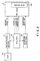
- Figure 2 is a block diagram of a control system for controlling the head driving circuit of Figure 1.
- Figure 3 is a timing chart for the signals controlling the head driving circuit of Figure 1.
- Figure 4 is a perspective view of an example of an ink jet recording head to which the present invention is applicable.
- Figure 5 is a circuit block diagram for a recording head driving circuit of a recording head or a recording apparatus according to another embodiment of the present invention.
- Figure 6 shows a waveform illustrating the principle of producing a driving pulse applied to the head driving circuit of Figure 5.
- Figure 7 shows a waveform of a driving pulse actually usable in the recording head driving circuit of Figure 5.
- Figure 8 is a block diagram of a control system for controlling the recording head driving circuit of Figure 5.
- Figure 9 shows a relation between image density non-uniformity signal and a waveform of a driving pulse for correcting the non-uniformity.
- FIG. 1 is a circuit block diagram of a driving circuit for an ink jet recording head of a so-called full-line type, according to an embodiment of the present invention.
- a heat generating element having an electrothermal transducer element is provided for each of approximately 3000 ejection or discharge outlets covering a width of the recording sheet.
- the thermal energy produced by the heat generating element 1 produces a bubble in the ink by film boiling. By the expansion of the bubble, the ink is ejected through the ejection outlet in the form of a droplet.
- the electric potential difference between the opposite ends of the heat generating element 1 is a driving voltage VH through a switching transistor 3.
- a base of the transistor 3 is connected to the output side of the associated AND gate 5.
- a shift resistor 13 functions to store one bit serial signal WD bearing waveform data supplied from a controller of the ink jet recording apparatus.
- the pulse width of the driving pulse is modulated in 16 steps. Therefore, consecutive four bits of the waveform data signal WD constitute one waveform data for the driving pulse.
- the shift resistor 13 has approximately 3000x4 bits, corresponding to the approximately 3000 heat generating elements 1.
- a counter 11 is provided for each of the heat generating elements.
- the 4 bit parallel waveform data transferred from the shift resistor 13 are set. The counter counts the clockpulses supplied from the controller the set waveform data, that is, counts as many as the clockpulses corresponding to the pulse width of the waveform, and the counter produces "H" level during the counting.
- a shift resistor 9 functions to store 1 bit serial record image signal ID. It has approximately 3000 bits, corresponding to the heat generating elements 1.
- a data buffer 7 latches in accordance with a latch signal LT the recording image signal ID produced from the shift register 9.
- Each of the AND gates 5 receives the associated output of the data buffer and receives an output of the associated counter 11.
- FIG 2 is a block diagram showing in detailed the controller for controlling the head driver circuit by transferring the above-described various signals to the head driver circuit 14A shown in Figure 1, of the recording head 14.
- a record image signal buffer 31 is effective to temporarily store the record image signal supplied from a host machine 30 such as a microcomputer.
- the buffer 31 functions to adjust the deviation between the record image signal transfer timing by the host machine 30 and the driving timing of the recording head 14 in response to the image signal.
- the machine for transferring the record image signal ID is not limited to the host machine such as computer, but it may be an original or document reader of a copying machine, facsimile machine, word processor or the like which is used with the ink jet recording apparatus of this embodiment as a printer, or it may be a simple input terminal such as keyboard in a printer.
- a wave data ROM 33 stores the waveform data WD for the driving pulse in accordance with the image density.
- the waveform data WD are stored in the ROM 33 for the individual heat generating elements when the apparatus is delivered from a plant or when a serviceman's adjusting operation is effected at regular intervals or at irregular intervals.
- a sequence controller 32 has a CPU or the like to control the record image signal transfer from the record image signal buffer 31 to the head driver circuit 14A and the waveform data WD transfer from the waveform data ROM 33 to the head driver circuit 14A. It also functions to supply the latching signal LT, the clock signal CK and the preset signal PS to the head driver circuit 14A at the proper timing.
- Figure 3 is a timing chart showing the transfer timing of each of the signals described above. Referring to Figure 3, the operational timing in the structure illustrated in Figures 1 and 2, will be described.
- the waveform data WD which have been set for the individual approximately 3000 sheet generating elements, are transferred from the waveform data ROM 33 to the shift register 13, at timing t1 in Figure 3.
- the record image signal ID is transferred from the record image signal buffer 31 to the shift register 9 in synchronism with the timing of the recording sheet feeding (timing t2).
- the record image signal ID is latched at the data buffer 7 in response to the latching signal LT having the level "L" (timing t4) and the output of the data to the AND gate 5 is set.
- the waveform data WD stored in the shift register 13 are set in the counters 11 in response to the preset signal PS having the level “L” (timing t3).
- the driving pulse having a width corresponding to the duration in which the logic "H” is produced from the counter 11 associated with the heat generating elements, so that consistent ink droplets are ejected irrespective of the variations in the heat generating elements per se.
- the recording operation is effected for one line corresponding to the length of the array of the ejection outlets of the recording head.
- the record image signal ID for the next line is supplied to the shift register 9, and the recording operation for the next line is effected in the similar manner.
- Figure 4 shows an example of an ink jet recording apparatus using the recording head and the driving system described in the foregoing. It is a perspective view of a full-color printer provided with four full-line type recording heads.
- the printer comprises pairs of rollers 201A and 201B for feeding the recording material R in a sub-scan direction Vs. It also comprises full-line type recording heads for black, yellow, magenta and cyan recording, each having approximately 3000 ejection outlets covering an entire recording width of the recording material R, as described in the foregoing. They are disposed in the order named from the upstream side with respect to the feeding direction of the recording material.
- a recovery system 200 is brought into facing relation to the recording heads 14BK - 14C in place of the recording material R upon an ejection recovery operation.
- the frequency of the ejection recovery operations can be remarkably reduced because a preliminary heating operation is carried out at proper timing.
- Figure 5 is a circuit block diagram of a recording head driving circuit of a recording head or a recording apparatus according to another embodiment of the present invention.
- two counters 11A and 11B are sequentially operated, so that the driving pulse waveform having two pulses shown in Figure 6 can be applied.
- the bit number of the shift register 15 is increased from that of Figure 1 structure, corresponding to the number of counters.
- OR gate 15 is used to obtain a logic sum of the counts of the counters 11A and 11B.
- the levels set in accordance with the waveform data stored in the shift register 13 are "4" and "8".
- the frequency of the clock pulses CKA and CKB is commonly 1 MHz, and the time difference between the first pulses of the clock pulse CKA and the clock pulse CKB is 8 micro-sec., for example.
- the driving pulse shown in Figure 7 is obtained.
- the quantity of the ink can be controlled by controlling the temperature of the ink because the viscosity of the ink is dependent on the temperature thereof.
- the first part of the two pulses may be used to control the temperature of the ink, thus permitting a long range ink ejection quantity control.
- FIG 8 is a block diagram of a controller for an ink jet recording apparatus using the recording head driver circuit shown in Figure 5.
- a sample image is recorded using the driving pulse of the waveform which has been set, and then, the provided image is optically read by a non-uniformity detector 35. By doing so, the actual image density non-uniformity can be detected.
- the image non-uniformity signal provided is transferred to a waveform data processor 34 which determines for the respective heat generating elements such drive pulse waveforms as to provide uniform image density for the picture elements provided by the ink droplets from the heat generating elements. Thereafter, the data are stored.
- the waveform data WD are constituted by 3 bits corresponding to the counter 11A and 4 bits corresponding to the counter 11B, that is, 7 bits in total. Then, it is transferred to the recording head driver circuit 140A in the form of a 1 bit serial signal.
- Figure 9 shows a relation between the waveform of the driving pulse and the image non-uniformity signal in this embodiment.
- the level of the image density non-uniformity signal increases with increase of the detected image density. Therefore, with the increase of the level of the non-uniformity signal, a pulse waveform providing smaller quantity of the ink ejection is selected in order to suppress the image density.
- the clock pulses CKA and CKB commonly had the frequency of 1 MHz, and the time difference between the clockpulses CKA and CKB was 6 micro-sec.
- the recorded images were of high quality without non-uniformity in the image density.
- the means for storing the waveform data WA for the driving pulses of the head driver circuit has been described as a shift register, but it may be in another form if it has a storing function. It may be, for example, RAM, ROM, flip-flop circuit or the like.
- the waveform data WD is not limited to the one inputted serially bit by bit.
- the present invention is not limited to the case wherein the pulse waveform is determined for each of the heat generating elements, but the pulse waveform is determined for every 8 heat generating elements, for example. With such a structure, a sufficiently high quality image can be provided.
- the present invention is applicable to a heat generating element in a thermal type recording head of a thermal transfer type or a heat sensitive type.
- the present invention is applicable to a recording element using other than thermal energy, for example, a piezoelectric element.
- the present invention is particularly suitably usable in an ink jet recording head and recording apparatus wherein thermal energy by an electrothermal transducer, laser beam or the like is used to cause a change of state of the ink to eject or discharge the ink. This is because the high density of the picture elements and the high resolution of the recording are possible.
- the typical structure and the operational principle are preferably the ones disclosed in U.S. Patent Nos. 4,723,129 and 4,740,796.
- the principle and structure are applicable to a so-called on-demand type recording system and a continuous type recording system.
- it is suitable for the on-demand type because the principle is such that at least one driving signal is applied to an electrothermal transducer disposed on a liquid (ink) retaining sheet or liquid passage, the driving signal being enough to provide such a quick temperature rise beyond a departure from nucleation boiling point, by which the thermal energy is provided by the electrothermal transducer to produce film boiling on the heating portion of the recording head, whereby a bubble can be formed in the liquid (ink) corresponding to each of the driving signals.
- the liquid (ink) is ejected through an ejection outlet to produce at least one droplet.
- the driving signal is preferably in the form of a pulse, because the development and contraction of the bubble can be effected instantaneously, and therefore, the liquid (ink) is ejected with quick response.
- the driving signal in the form of the pulse is preferably such as disclosed in U.S. Patents Nos. 4,463,359 and 4,345,262.
- the temperature increasing rate of the heating surface is preferably such as disclosed in U.S. Patent No. 4,313,124.
- the structure of the recording head may be as shown in U.S. Patent Nos. 4,558,333 and 4,459,600 wherein the heating portion is disposed at a bent portion, as well as the structure of the combination of the ejection outlet, liquid passage and the electrothermal transducer as disclosed in the above-mentioned patents.
- the present invention is applicable to the structure disclosed in Japanese Laid-Open Patent Application No. 123670/1984 wherein a common slit is used as the ejection outlet for plural electrothermal transducers, and to the structure disclosed in Japanese Laid-Open Patent Application No. 138461/1984 wherein an opening for absorbing pressure waves of the thermal energy is formed corresponding to the ejecting portion. This is because the present invention is effective to perform the recording operation with certainty and at high efficiency irrespective of the type of the recording head.
- the present invention is effectively applicable to a so-called full-line type recording head having a length corresponding to the maximum recording width.
- a recording head may comprise a single recording head and plural recording head combined to cover the maximum width.
- the present invention is applicable to a serial type recording head wherein the recording head is fixed on the main assembly, to a replaceable chip type recording head which is connected electrically with the main apparatus and can be supplied with the ink when it is mounted in the main assembly, or to a cartridge type recording head having an integral ink container.
- the provisions of the recovery means and/or the auxiliary means for the preliminary operation are preferable, because they can further stabilize the effects of the present invention.
- preliminary heating means which may be the electrothermal transducer, an additional heating element or a combination thereof.
- means for effecting preliminary ejection (not for the recording operation) can stabilize the recording operation.
- the recording head mountable may be a single head corresponding to a single color ink, or may be plural heads corresponding to the plurality of ink materials having different recording colors or densities.
- the present invention is effectively applicable to an apparatus having at least one of a monochromatic mode mainly with black, a multi-color mode with different color ink materials and/or a full-color mode using the mixture of the colors, which may be an integrally formed recording unit or a combination of plural recording heads.
- the ink has been liquid. It may be, however, an ink material which is solidified below the room temperature but liquefied at the room temperature. Since the ink is controlled within the temperature not lower than 30 °C and not higher than 70 °C to stabilize the viscosity of the ink to provide the stabilized ejection in usual recording apparatus of this type, the ink may be such that it is liquid within the temperature range when the recording signal is applied.
- the present invention is also applicable to other types of ink. In one of them, the temperature rise due to the thermal energy is positively prevented by consuming it for the state change of the ink from the solid state to the liquid state. Another ink material is solidified when it is unheated, to prevent the evaporation of the ink.
- the ink is liquefied, and the liquefied ink may be ejected.
- Another ink material may start to be solidified at the time when it reaches the recording material.
- the present invention is also applicable to such an ink material as is liquefied by the application of the thermal energy.
- Such an ink material may be retained as a liquid or solid material in through holes or recesses formed in a porous sheet as disclosed in Japanese Laid-Open Patent Application No. 56847/1979 and Japanese Laid-Open Patent Application No. 71260/1985. The sheet is faced to the electrothermal transducers.
- the most effective system for the ink materials described above is the film boiling system.
- the ink jet recording apparatus may be used as an output terminal of an information processing apparatus such as computer or the like, as a copying apparatus combined with an image reader or the like, or as a facsimile machine having information sending and receiving functions.
- the waveform data for the driving pulse is stored in a memory circuit, and the driving pulse for the waveform data can be applied to the associated heat generating elements corresponding to the record image signal.
- the waveform data signal for the driving pulse is not used also as the recording signal, and therefore, the bulky circuit for effecting the waveform data control in synchronism with the transfer of the recording image signal can be omitted. By doing so, the structure of the recording head is simplified. In addition, the correction of the property variation among the heat generating elements can be effected quickly by the waveform data.
- the size of the recording element part can be reduced in a recording apparatus particularly in the recording apparatus having plural full-line recording heads having a great number of thermal energy generating elements at a high density. Therefore, the sizes of the entire facsimile, copying, word processor machine or the like or another printer can be reduced.
Landscapes
- Particle Formation And Scattering Control In Inkjet Printers (AREA)
- Ink Jet (AREA)
- Electronic Switches (AREA)
- Color, Gradation (AREA)
- Dot-Matrix Printers And Others (AREA)
Claims (21)
- Tête d'enregistrement comportant plusieurs éléments d'enregistrement destinés à éjecter de l'encre ; et
des moyens (13) de stockage de formes d'ondes destinés à stocker des données de formes d'ondes (WD) pour un signal ou des signaux d'attaque appliqués auxdits éléments d'enregistrement, caractérisée par
des moyens de comptage (11) destinés à compter une période en conformité avec la donnée de forme d'onde ; et
des moyens (3, 5, 7, 9) d'application de signaux d'attaque destinés à appliquer à chacun d'un nombre prédéterminé desdits éléments d'enregistrement au moins un signal d'attaque sur la base de la période comptée par lesdits moyens de comptage, conformément à au moins un signal d'image d'enregistrement, ledit nombre prédéterminé étant au moins égal à un, la donnée de forme d'onde définissant une largeur dudit, au moins un, signal d'attaque pour régler la quantité d'encre éjectée. - Tête d'enregistrement selon la revendication 1, caractérisée en ce que le nombre prédéterminé est égal à un.
- Tête d'enregistrement selon la revendication 1, caractérisée en ce que le nombre prédéterminé est supérieur à un.
- Tête d'enregistrement selon la revendication 1, caractérisée en ce que ledit, au moins un, signal d'attaque comprend au moins deux signaux à impulsions.
- Tête d'enregistrement selon l'une quelconque des revendications 1-4, caractérisée en ce que lesdits éléments d'enregistrement pour éjecter de l'encre comprennent des éléments (1) de génération de chaleur destinés à produire de l'énergie thermique en réponse à des signaux d'attaque pour provoquer un changement d'état de l'encre.
- Appareil d'enregistrement comportant une tête d'enregistrement selon l'une quelconque des revendications 1-5, caractérisé par
des moyens de transfert destinés à transférer ledit, au moins un, signal d'image d'enregistrement auxdits moyens d'application de signaux d'attaque ; et
des moyens de commande destinés à commander le temps d'application dudit, au moins un, signal d'attaque. - Appareil selon la revendication 6, caractérisé en ce que des moyens d'établissement de données de formes d'ondes sont prévus pour transférer les données de formes d'ondes auxdits moyens de stockage de formes d'ondes afin de stocker les données de formes d'ondes dans lesdits moyens de stockage.
- Appareil selon la revendication 7, caractérisé en ce que lesdits moyens d'établissement comprennent un élément de stockage de formes d'ondes destiné à stocker la donnée de forme d'onde correspondant à une densité d'image.
- Appareil selon la revendication 7, dans lequel lesdits moyens d'établissement de données de formes d'ondes comprennent des moyens de lecture d'image destinés à lire une image produite par ladite tête d'enregistrement avant une opération d'enregistrement et des moyens de traitement destinés à corriger la donnée de forme d'onde sur la base de données lues par les moyens de lecture.
- Appareil selon la revendication 9, caractérisé en ce qu'un circuit (9) de stockage de signaux d'images est prévu pour stocker ledit, au moins un, signal d'image enregistré.
- Appareil selon la revendication 10, caractérisé en ce que lesdits moyens de lecture fournissent ledit, au moins un, signal d'image enregistré audit circuit de stockage de signaux d'images.
- Appareil selon la revendication 10 ou 11, caractérisé en ce que des moyens d'entrée de signaux d'images sont prévus pour fournir ledit, au moins un, signal d'image enregistré audit circuit de stockage de signaux d'images.
- Appareil selon l'une quelconque des revendications 1-12, caractérisé en ce que les éléments d'enregistrement sont disposés sur une largeur entière d'enregistrement d'un support d'enregistrement.
- Appareil selon l'une quelconque des revendications 1-13, caractérisé en ce que ladite tête d'enregistrement effectue une opération d'enregistrement en utilisant plusieurs couleurs d'encre.
- Procédé d'enregistrement utilisant une tête d'enregistrement ayant plusieurs éléments d'enregistrement, comprenant les étapes qui consistent :
à stocker des données de formes d'ondes pour au moins un signal d'attaque appliqué à un nombre prédéterminé des éléments d'enregistrement, le nombre prédéterminé étant égal à au moins à un, les données de formes d'ondes définissant une largeur dudit, au moins un, signal d'attaque ;
à compter une période de temps conforme aux données de formes d'ondes ;
à appliquer à chacun du nombre prédéterminé des éléments d'enregistrement un signal d'image d'enregistrement ;
à délivrer en sortie un signal d'attaque au nombre prédéterminé des éléments d'enregistrement sur la base de la période de temps comptée dans ladite étape de comptage, conformément au signal d'image d'enregistrement appliqué ; et
à répéter, pendant une opération d'enregistrement, lesdites étape de comptage, étape d'application et étape de délivrance en sortie. - Procédé selon la revendication 15, caractérisé en ce que ladite étape de stockage est exécutée après l'actionnement d'un interrupteur principal pour alimenter en énergie la tête d'enregistrement.
- Procédé selon la revendication 15 ou 16, caractérisé en ce que ledit, au moins un, signal d'attaque comprend au moins deux signaux à impulsions.
- Procédé selon la revendication 15, 16 ou 17, caractérisé en ce que le nombre prédéterminé est égal à un.
- Procédé selon la revendication 15, 16 ou 17, caractérisé en ce que le nombre prédéterminé est supérieur à un.
- Procédé selon l'une quelconque des revendications 15-19, caractérisé en ce que les éléments d'enregistrement comprennent des éléments de génération de chaleur qui produisent de l'énergie thermique en réponse audit, au moins un, signal d'attaque pour provoquer un changement d'état de l'encre afin d'éjecter l'encre.
- Procédé selon l'une quelconque des revendications 15-19, caractérisé en ce que les données de formes d'ondes ont pour effet de limiter la largeur dudit, au moins un, signal d'attaque afin de régler la quantité de l'encre éjectée.
Applications Claiming Priority (2)
| Application Number | Priority Date | Filing Date | Title |
|---|---|---|---|
| JP2022189A JP2857445B2 (ja) | 1990-02-02 | 1990-02-02 | 記録ヘッドおよび記録装置 |
| JP22189/90 | 1990-02-02 |
Publications (2)
| Publication Number | Publication Date |
|---|---|
| EP0445916A1 EP0445916A1 (fr) | 1991-09-11 |
| EP0445916B1 true EP0445916B1 (fr) | 1995-10-11 |
Family
ID=12075852
Family Applications (1)
| Application Number | Title | Priority Date | Filing Date |
|---|---|---|---|
| EP91300803A Expired - Lifetime EP0445916B1 (fr) | 1990-02-02 | 1991-01-31 | Tête d'enregistrement et appareil d'enregistrement utilisant celle-ci |
Country Status (4)
| Country | Link |
|---|---|
| US (2) | US5305024A (fr) |
| EP (1) | EP0445916B1 (fr) |
| JP (1) | JP2857445B2 (fr) |
| DE (1) | DE69113657T2 (fr) |
Families Citing this family (32)
| Publication number | Priority date | Publication date | Assignee | Title |
|---|---|---|---|---|
| JP2857445B2 (ja) * | 1990-02-02 | 1999-02-17 | キヤノン株式会社 | 記録ヘッドおよび記録装置 |
| DE69233179T2 (de) | 1991-01-18 | 2004-06-17 | Canon K.K. | Tintenstrahlaufzeichnungsverfahren und Vorrichtung mit thermischer Energie |
| US6076919A (en) * | 1991-08-12 | 2000-06-20 | Canon Kabushiki Kaisha | Jet recording method |
| US5438352A (en) * | 1993-08-02 | 1995-08-01 | Fuji Photo Film Co., Ltd. | Method of and apparatus for recording an image in a first direction while the recording means is being relatively moved and the images being dispersed in a second direction which is substantially paralled to the first direction |
| US5519426A (en) * | 1993-11-01 | 1996-05-21 | Lasermaster Corporation | Method for controlling a thermal printer to increase resolution |
| US6116714A (en) * | 1994-03-04 | 2000-09-12 | Canon Kabushiki Kaisha | Printing head, printing method and apparatus using same, and apparatus and method for correcting said printing head |
| JPH07290707A (ja) * | 1994-04-22 | 1995-11-07 | Canon Inc | 記録ヘッド及び該記録ヘッドを用いたプリンタ装置及びプリント方法 |
| JP3086132B2 (ja) * | 1994-07-29 | 2000-09-11 | キヤノン株式会社 | インクジェット記録装置 |
| JP3581445B2 (ja) * | 1994-08-24 | 2004-10-27 | キヤノン株式会社 | 記録方法およびその装置 |
| US5608442A (en) * | 1994-08-31 | 1997-03-04 | Lasermaster Corporation | Heating control for thermal printers |
| JP3174225B2 (ja) * | 1994-10-27 | 2001-06-11 | キヤノン株式会社 | 記録ヘッド及び該記録ヘッドを用いた記録方法及び装置 |
| JPH09109389A (ja) * | 1995-10-23 | 1997-04-28 | Rohm Co Ltd | インクジェット記録装置の記録素子駆動用集積回路 |
| US6352328B1 (en) * | 1997-07-24 | 2002-03-05 | Eastman Kodak Company | Digital ink jet printing apparatus and method |
| JP3557883B2 (ja) * | 1997-12-16 | 2004-08-25 | ブラザー工業株式会社 | インク滴噴射方法及びその装置 |
| US6270188B1 (en) | 1998-01-29 | 2001-08-07 | Fuji Photo Film Co., Ltd. | Ink jet printer and control method thereof |
| CN1103287C (zh) * | 1998-03-31 | 2003-03-19 | 财团法人工业技术研究院 | 延长热气泡式喷墨印头使用寿命的方法 |
| US6126260A (en) * | 1998-05-28 | 2000-10-03 | Industrial Technology Research Institute | Method of prolonging lifetime of thermal bubble inkjet print head |
| US6318845B1 (en) * | 1998-07-10 | 2001-11-20 | Canon Kabushiki Kaisha | Ink-jet printing apparatus and method for varying energy for ink ejection for high and low ejection duties |
| US6761434B2 (en) | 2000-07-27 | 2004-07-13 | Canon Kabushiki Kaisha | Liquid discharge head, element substrate, liquid discharging apparatus and liquid discharging method |
| DE60134929D1 (de) | 2000-09-29 | 2008-09-04 | Canon Kk | Tintenstrahldruckvorrichtung und Tintenstrahldruckverfahren |
| DE60204485T2 (de) | 2001-01-05 | 2006-03-16 | Hewlett-Packard Development Co., L.P., Houston | Integrierter programmierbarer Auslösepulsgenerator für Tintenstrahldruckkopf |
| US6585339B2 (en) | 2001-01-05 | 2003-07-01 | Hewlett Packard Co | Module manager for wide-array inkjet printhead assembly |
| US6726300B2 (en) * | 2002-04-29 | 2004-04-27 | Hewlett-Packard Development Company, L.P. | Fire pulses in a fluid ejection device |
| US6913345B2 (en) * | 2003-03-21 | 2005-07-05 | Lexmark International, Inc. | Method and apparatus for firing nozzles in an ink jet printer |
| US7281778B2 (en) * | 2004-03-15 | 2007-10-16 | Fujifilm Dimatix, Inc. | High frequency droplet ejection device and method |
| US8491076B2 (en) * | 2004-03-15 | 2013-07-23 | Fujifilm Dimatix, Inc. | Fluid droplet ejection devices and methods |
| EP1836056B1 (fr) | 2004-12-30 | 2018-11-07 | Fujifilm Dimatix, Inc. | Impression a jet d'encre |
| US7568776B2 (en) | 2005-03-01 | 2009-08-04 | Brother Kogyo Kabushiki Kaisha | Recording apparatus |
| JP4765346B2 (ja) * | 2005-03-14 | 2011-09-07 | ブラザー工業株式会社 | 記録装置 |
| US7988247B2 (en) | 2007-01-11 | 2011-08-02 | Fujifilm Dimatix, Inc. | Ejection of drops having variable drop size from an ink jet printer |
| US8393702B2 (en) * | 2009-12-10 | 2013-03-12 | Fujifilm Corporation | Separation of drive pulses for fluid ejector |
| WO2017180142A1 (fr) * | 2016-04-14 | 2017-10-19 | Hewlett-Packard Development Company, L.P. | Réglage de largeur d'impulsion d'amorçage |
Family Cites Families (24)
| Publication number | Priority date | Publication date | Assignee | Title |
|---|---|---|---|---|
| CA1127227A (fr) * | 1977-10-03 | 1982-07-06 | Ichiro Endo | Procede d'enregistrement a jet liquide et appareil d'enregistrement |
| JPS5936879B2 (ja) * | 1977-10-14 | 1984-09-06 | キヤノン株式会社 | 熱転写記録用媒体 |
| US4330787A (en) * | 1978-10-31 | 1982-05-18 | Canon Kabushiki Kaisha | Liquid jet recording device |
| US4345262A (en) * | 1979-02-19 | 1982-08-17 | Canon Kabushiki Kaisha | Ink jet recording method |
| US4463359A (en) * | 1979-04-02 | 1984-07-31 | Canon Kabushiki Kaisha | Droplet generating method and apparatus thereof |
| US4313124A (en) * | 1979-05-18 | 1982-01-26 | Canon Kabushiki Kaisha | Liquid jet recording process and liquid jet recording head |
| US4558333A (en) * | 1981-07-09 | 1985-12-10 | Canon Kabushiki Kaisha | Liquid jet recording head |
| JPS58168574A (ja) * | 1982-03-31 | 1983-10-04 | Fujitsu Ltd | インクジエツト記録装置の駆動回路 |
| US4521786A (en) * | 1982-09-20 | 1985-06-04 | Xerox Corporation | Programmable driver/controller for ink jet printheads |
| JPS59104950A (ja) * | 1982-12-07 | 1984-06-18 | Seiko Epson Corp | インクジエツトヘツド駆動方法 |
| JPS59123670A (ja) * | 1982-12-28 | 1984-07-17 | Canon Inc | インクジエツトヘツド |
| JPS59138461A (ja) * | 1983-01-28 | 1984-08-08 | Canon Inc | 液体噴射記録装置 |
| US4574293A (en) * | 1983-05-23 | 1986-03-04 | Fuji Xerox Co., Ltd. | Compensation for heat accumulation in a thermal head |
| JPS6071260A (ja) * | 1983-09-28 | 1985-04-23 | Erumu:Kk | 記録装置 |
| JPS62256667A (ja) * | 1986-04-30 | 1987-11-09 | Sony Corp | 感熱ヘツド駆動回路の補正回路 |
| JPH0785937B2 (ja) * | 1986-09-12 | 1995-09-20 | 三菱電機株式会社 | ドライバic及び記録ヘッド |
| US5264865A (en) * | 1986-12-17 | 1993-11-23 | Canon Kabushiki Kaisha | Ink jet recording method and apparatus utilizing temperature dependent, pre-discharge, meniscus retraction |
| JPS6426454A (en) * | 1987-04-17 | 1989-01-27 | Canon Kk | Ink jet recorder |
| JPH0729421B2 (ja) * | 1987-04-24 | 1995-04-05 | 松下電器産業株式会社 | インクジエツトプリンタ |
| JPS6430949A (en) * | 1987-07-23 | 1989-02-01 | Toyota Motor Corp | Planetary gear type multi stage transmission |
| DE3885238T2 (de) * | 1987-11-27 | 1994-03-03 | Canon Kk | Tintenstrahlaufzeichnungsgerät. |
| JPH0255143A (ja) * | 1988-08-18 | 1990-02-23 | Ricoh Co Ltd | インクジェット記録装置 |
| JP2690773B2 (ja) * | 1989-03-10 | 1997-12-17 | キヤノン株式会社 | インクジェット記録装置およびインクジェット記録方法 |
| JP2857445B2 (ja) * | 1990-02-02 | 1999-02-17 | キヤノン株式会社 | 記録ヘッドおよび記録装置 |
-
1990
- 1990-02-02 JP JP2022189A patent/JP2857445B2/ja not_active Expired - Fee Related
-
1991
- 1991-01-31 DE DE69113657T patent/DE69113657T2/de not_active Expired - Lifetime
- 1991-01-31 EP EP91300803A patent/EP0445916B1/fr not_active Expired - Lifetime
- 1991-02-01 US US07/649,732 patent/US5305024A/en not_active Expired - Lifetime
-
1997
- 1997-04-07 US US08/826,762 patent/US5975667A/en not_active Expired - Fee Related
Also Published As
| Publication number | Publication date |
|---|---|
| EP0445916A1 (fr) | 1991-09-11 |
| JP2857445B2 (ja) | 1999-02-17 |
| US5305024A (en) | 1994-04-19 |
| US5975667A (en) | 1999-11-02 |
| DE69113657T2 (de) | 1996-03-21 |
| JPH03227663A (ja) | 1991-10-08 |
| DE69113657D1 (de) | 1995-11-16 |
Similar Documents
| Publication | Publication Date | Title |
|---|---|---|
| EP0445916B1 (fr) | Tête d'enregistrement et appareil d'enregistrement utilisant celle-ci | |
| EP0551013B1 (fr) | Ensemble de tête d'enregistrement pour appareil d'enregistrement par jet d'encre et sa méthode de commande | |
| EP0440500B1 (fr) | Tête d'enregistrement à jet d'encre et appareil d'enregistrement à jet d'encre incorporant cette tête d'enregistrement | |
| EP0390202B1 (fr) | Tête d'enregistrement à jet d'encre, méthode d'excitation pour celle-ci et appareil d'enregistrement à jet d'encre | |
| EP0440490B1 (fr) | Procédé et appareil d'enregistrement | |
| US5880751A (en) | Ink jet recording apparatus and ink droplet amount ejection control method therefor | |
| US6224195B1 (en) | Recording head and recording apparatus using the same | |
| EP0698492B1 (fr) | Procédé et appareil pour subdiviser des blocs | |
| EP0595658A2 (fr) | Appareil d'enregistrement par jet d'encre | |
| EP0864424B1 (fr) | Dispositif d'enregistrement à jet d'encre et méthode de commande d'une quantité d'encre déchargée après une interruption dans l'enregistrement | |
| EP0747221B1 (fr) | Tête à jet d'encre, appareil à jet d'encre et méthode d'enregistrement par jet d'encre | |
| EP0440489B1 (fr) | Appareil d'enregistrement et méthode utilisant une tête d'enregistrement à jet d'encre | |
| JP3667118B2 (ja) | 記録装置および記録方法 | |
| US5988785A (en) | Recording apparatus and method for driving recording head element groups in a partially overlapped manner | |
| EP0732217B1 (fr) | Tête et appareil d'enregistrement pour la détection de contact | |
| JP2746717B2 (ja) | インクジェット記録装置 | |
| JP2986883B2 (ja) | インクジェット記録装置 | |
| US6428136B2 (en) | Ink jet recording method and ink jet recorder | |
| JP4402911B2 (ja) | インクジェット記録装置及び方法 | |
| US5808632A (en) | Recording apparatus and method using ink jet recording head | |
| JP3131104B2 (ja) | プリンタ装置 | |
| JP3133841B2 (ja) | 画像形成装置 | |
| JP2752492B2 (ja) | 記録装置 | |
| JP2001054948A (ja) | インクジェット記録装置及び記録ヘッド駆動方法 | |
| JPH08108598A (ja) | データ出力装置 |
Legal Events
| Date | Code | Title | Description |
|---|---|---|---|
| PUAI | Public reference made under article 153(3) epc to a published international application that has entered the european phase |
Free format text: ORIGINAL CODE: 0009012 |
|
| AK | Designated contracting states |
Kind code of ref document: A1 Designated state(s): DE FR GB IT |
|
| 17P | Request for examination filed |
Effective date: 19920128 |
|
| 17Q | First examination report despatched |
Effective date: 19930915 |
|
| GRAA | (expected) grant |
Free format text: ORIGINAL CODE: 0009210 |
|
| AK | Designated contracting states |
Kind code of ref document: B1 Designated state(s): DE FR GB IT |
|
| REF | Corresponds to: |
Ref document number: 69113657 Country of ref document: DE Date of ref document: 19951116 |
|
| ITF | It: translation for a ep patent filed | ||
| ET | Fr: translation filed | ||
| PLBE | No opposition filed within time limit |
Free format text: ORIGINAL CODE: 0009261 |
|
| STAA | Information on the status of an ep patent application or granted ep patent |
Free format text: STATUS: NO OPPOSITION FILED WITHIN TIME LIMIT |
|
| 26N | No opposition filed | ||
| REG | Reference to a national code |
Ref country code: GB Ref legal event code: IF02 |
|
| PGFP | Annual fee paid to national office [announced via postgrant information from national office to epo] |
Ref country code: IT Payment date: 20090119 Year of fee payment: 19 |
|
| PGFP | Annual fee paid to national office [announced via postgrant information from national office to epo] |
Ref country code: FR Payment date: 20090121 Year of fee payment: 19 |
|
| PGFP | Annual fee paid to national office [announced via postgrant information from national office to epo] |
Ref country code: DE Payment date: 20100131 Year of fee payment: 20 Ref country code: GB Payment date: 20100126 Year of fee payment: 20 |
|
| REG | Reference to a national code |
Ref country code: FR Ref legal event code: ST Effective date: 20100930 |
|
| PG25 | Lapsed in a contracting state [announced via postgrant information from national office to epo] |
Ref country code: FR Free format text: LAPSE BECAUSE OF NON-PAYMENT OF DUE FEES Effective date: 20100201 |
|
| REG | Reference to a national code |
Ref country code: GB Ref legal event code: PE20 Expiry date: 20110130 |
|
| PG25 | Lapsed in a contracting state [announced via postgrant information from national office to epo] |
Ref country code: IT Free format text: LAPSE BECAUSE OF NON-PAYMENT OF DUE FEES Effective date: 20100131 |
|
| PG25 | Lapsed in a contracting state [announced via postgrant information from national office to epo] |
Ref country code: GB Free format text: LAPSE BECAUSE OF EXPIRATION OF PROTECTION Effective date: 20110130 |
|
| PG25 | Lapsed in a contracting state [announced via postgrant information from national office to epo] |
Ref country code: DE Free format text: LAPSE BECAUSE OF EXPIRATION OF PROTECTION Effective date: 20110131 |