EP0445946A1 - Dauereinsatzteil zur Belüftung des Mittelohrraumes - Google Patents
Dauereinsatzteil zur Belüftung des Mittelohrraumes Download PDFInfo
- Publication number
- EP0445946A1 EP0445946A1 EP91301488A EP91301488A EP0445946A1 EP 0445946 A1 EP0445946 A1 EP 0445946A1 EP 91301488 A EP91301488 A EP 91301488A EP 91301488 A EP91301488 A EP 91301488A EP 0445946 A1 EP0445946 A1 EP 0445946A1
- Authority
- EP
- European Patent Office
- Prior art keywords
- tube
- flange
- base portion
- tube according
- middle ear
- Prior art date
- Legal status (The legal status is an assumption and is not a legal conclusion. Google has not performed a legal analysis and makes no representation as to the accuracy of the status listed.)
- Granted
Links
- 210000000959 ear middle Anatomy 0.000 title abstract description 18
- 238000009423 ventilation Methods 0.000 claims abstract description 20
- 239000000560 biocompatible material Substances 0.000 claims description 6
- RTAQQCXQSZGOHL-UHFFFAOYSA-N Titanium Chemical compound [Ti] RTAQQCXQSZGOHL-UHFFFAOYSA-N 0.000 claims description 2
- 229910052719 titanium Inorganic materials 0.000 claims description 2
- 239000010936 titanium Substances 0.000 claims description 2
- 239000011148 porous material Substances 0.000 claims 1
- 238000000034 method Methods 0.000 abstract description 14
- 239000000463 material Substances 0.000 abstract description 10
- 210000003454 tympanic membrane Anatomy 0.000 description 23
- 210000000883 ear external Anatomy 0.000 description 7
- 210000000988 bone and bone Anatomy 0.000 description 6
- 238000003780 insertion Methods 0.000 description 6
- 230000037431 insertion Effects 0.000 description 6
- 239000007943 implant Substances 0.000 description 5
- 210000001519 tissue Anatomy 0.000 description 5
- 238000001125 extrusion Methods 0.000 description 4
- 230000014759 maintenance of location Effects 0.000 description 4
- 238000002513 implantation Methods 0.000 description 3
- 238000005553 drilling Methods 0.000 description 2
- 230000001815 facial effect Effects 0.000 description 2
- 239000012530 fluid Substances 0.000 description 2
- 229920002379 silicone rubber Polymers 0.000 description 2
- 238000001356 surgical procedure Methods 0.000 description 2
- 206010033081 Otitis media chronic Diseases 0.000 description 1
- 239000004699 Ultra-high molecular weight polyethylene Substances 0.000 description 1
- 201000000946 adhesive otitis media Diseases 0.000 description 1
- 230000015572 biosynthetic process Effects 0.000 description 1
- 238000003486 chemical etching Methods 0.000 description 1
- 201000010354 chronic purulent otitis media Diseases 0.000 description 1
- 238000004891 communication Methods 0.000 description 1
- 230000003247 decreasing effect Effects 0.000 description 1
- 210000000613 ear canal Anatomy 0.000 description 1
- 210000003027 ear inner Anatomy 0.000 description 1
- 210000000256 facial nerve Anatomy 0.000 description 1
- 229910052588 hydroxylapatite Inorganic materials 0.000 description 1
- 208000015181 infectious disease Diseases 0.000 description 1
- 210000001595 mastoid Anatomy 0.000 description 1
- 208000005923 otitis media with effusion Diseases 0.000 description 1
- XYJRXVWERLGGKC-UHFFFAOYSA-D pentacalcium;hydroxide;triphosphate Chemical compound [OH-].[Ca+2].[Ca+2].[Ca+2].[Ca+2].[Ca+2].[O-]P([O-])([O-])=O.[O-]P([O-])([O-])=O.[O-]P([O-])([O-])=O XYJRXVWERLGGKC-UHFFFAOYSA-D 0.000 description 1
- 230000002085 persistent effect Effects 0.000 description 1
- 229920001296 polysiloxane Polymers 0.000 description 1
- 230000000717 retained effect Effects 0.000 description 1
- 231100000241 scar Toxicity 0.000 description 1
- 208000024036 serous otitis media Diseases 0.000 description 1
- 239000004945 silicone rubber Substances 0.000 description 1
- 230000008467 tissue growth Effects 0.000 description 1
- 229920000785 ultra high molecular weight polyethylene Polymers 0.000 description 1
Images

Classifications
-
- A—HUMAN NECESSITIES
- A61—MEDICAL OR VETERINARY SCIENCE; HYGIENE
- A61F—FILTERS IMPLANTABLE INTO BLOOD VESSELS; PROSTHESES; DEVICES PROVIDING PATENCY TO, OR PREVENTING COLLAPSING OF, TUBULAR STRUCTURES OF THE BODY, e.g. STENTS; ORTHOPAEDIC, NURSING OR CONTRACEPTIVE DEVICES; FOMENTATION; TREATMENT OR PROTECTION OF EYES OR EARS; BANDAGES, DRESSINGS OR ABSORBENT PADS; FIRST-AID KITS
- A61F11/00—Methods or devices for treatment of the ears or hearing sense; Non-electric hearing aids; Methods or devices for enabling ear patients to achieve auditory perception through physiological senses other than hearing sense; Protective devices for the ears, carried on the body or in the hand
- A61F11/20—Ear surgery
- A61F11/202—Surgical middle-ear ventilation or drainage, e.g. permanent; Implants therefor
Definitions
- the present invention relates to an apparatus and method for permanent ventilation of the middle ear.
- Ventilation tubes through the tympanic membrane has disadvantages because tissue growth and other factors cause movement and eventual extrusion of the tube from the tympanic membrane. Extrusion of a ventilation tube enhances the risk of perforation of the tympanic membrane which can require surgery to repair and could result in the formation of scar tissue on the tympanic membrane.
- Ventilation tubes have been designed for longer retention in the tympanic membrane. These tubes generally have enlarged flanges and are formed of compressible materials such as silicon rubber. In such tubes, the flanges are compressed for insertion through an incision in the tympanic membrane and released in the middle ear cavity. These large flanges operate to anchor the ventilation tube and inhibit easy extrusion. While large-flanged ventilation tubes may be retained for a longer period of time, they suffer from the same extrusion and perforation problems discussed above and generally are extruded within three to four years after insertion.
- the compressible materials used such as the silicone rubber are not suitable for permanent implantation.
- the materials have been described as having a "tacky" surface, which is somewhat porous and causes retention of fluid on the implant, impeding drainage and increasing risk of infection. More suitable biocompatible materials are not useful in these large-flanged implants because of their rigid structure.
- US Patent 3982545 describes another type of ventilation tube deemed to be permanent, which is inserted through a specific region of the bony external ear canal. Although this tube is designed to be permanent, it also has problems. As described in United States Patent 3982545, the tube is installed by the relatively complicated surgical procedure of first exposing the middle ear structure by cutting a flap in the tympanic membrane to determine whether the patient's facial recess and bony overhang are adequate for the procedure. This procedure opens the tympanic membrane and requires drainage of the middle ear during the procedure. This procedure also requires drilling through the facial ridge or alternatively through the mastoid air cells, with the concomitant risk of damage to the facial nerve. The implant described in United States Patent 3982545 is also formed of a compressible material such as silicone to facilitate its insertion and retention in the drilled canal, which has the problems discussed above.
- the present invention provides a permanent ventilation tube for the middle ear, which solves the problems discussed above.
- a permanent ear ventilation tube comprising
- the longitudinal opening extends through the flange
- the base portion and flange are formed of a non-compressible, biocompatible material.
- the ventilation tube of the present invention is formed of a biocompatible material which may be porous or dense and is preferably non-compressible.
- the ventilation tube of the present invention includes a tubal base portion with an eccentric flange at the proximal end of the base portion for insertion and permanent retention in the middle ear cavity.
- the distal end can be beveled on the side opposite the flange to facilitate drainage.
- the tube is installed by separating the fibrous annulus of the tympanic membrane from the bony canal wall and forming a groove in the bone of the external canal.
- the ventilation tube is then inserted into the drilled canal.
- the implant is then rotated and pushed to rest the length of the tubular base portion in the groove in the bone of the external canal. In its final position, the flange of the implant rests along the vertical wall of the middle ear chamber while the opposite end of the tubular base portion projects into the outer ear cavity.
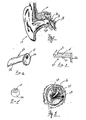
- FIG. 1 illustrates a typical ear 10 which includes an outer ear cavity 12 and middle ear cavity 14 separated by a tympanic membrane 16. Vibrations caused by sound waves impinging on the tympanic membrane 16 are transmitted in the form of vibrations through a chain of three movable bones known as ossicles 18 to the internal ear (not shown).
- a ventilation tube 20 of the present invention is shown inserted under the tympanic membrane 16 in order to provide communication between the outer and middle ear cavities 12, 14, respectively, for the reasons discussed above.
- the method of insertion is described in greater below.
- the tube 20, shown in detail in Figs. 2-4, includes an elongated tubular base portion 22 with an opening or lumen 24 extending throughout the length of the base portion 22.
- a flange 26 is formed at the proximal end of the base portion 22. As shown best in Fig. 4, the flange 26 is circular in shape and eccentrically arranged so that it is flush against one side of the tubular member 22.
- the flange 26 extends perpendicularly away from the opposite side of the tubular member 22 so that the outer wall of the base portion member 22, see Fig. 4, is tangential to the outer edge of the circular flange 26.
- This structure of the tube with what is called an eccentric flange allows the tube to be inserted easily into an opening formed in the tympanic membrane through a "buttoning" process as described below.
- the distal end of the tube 22 is preferably beveled at an angle A greater than 20°, preferably about 45°.
- This beveled surface 28 is at the opposite end of the bod 20 to the extended edge of the flange 26 so that as shown in Fig.1, the beveled end faces away from the wall that defines the outer ear canal 12 to allow ventilation between the middle ear cavity 14 and outer ear cavity 12.
- the ventilation tube 20 is formed of a non-compressible biocompatible material.
- the material can be formed with a porous outer surface or one which encourages surface adhesion of surrounding material.
- suitable known materials with a porous outer surface to encourage tissue ingrowth are porous ultra-high molecular weight polyethylene.
- Other known biocompatible materials designed to allow for surface adhesion of surrounding tissue are dense hydroxylapatite which encourages osteointegration or surface adhesion of surrounding tissue to the outer surface of the tube 20.
- Another suitable material is titanium with a matte surface formed by chemical etching which has also been found to provide suitable surface adhesion of surrounding tissue.
- the tube 20 is implanted at the outer perimeter of the tympanic membrane 16 under a fibrous ring 30 which connects the tympanic membrane 16 to surrounding bone 32.
- An advantage of the tube and method of the present invention is that the tube 20 can be implanted at any desired point around the periphery of the tympanic membrane 16.
- the method of implanting the tube 20 includes drilling an notch with a suitable microsurgical drill bit 34 into the bony annulus of the tympanic membrane ring 30 preferably forming a small notch in the surrounding bone 32.
- the beveled or distal end 28 of the tube 20 is grasped by a pair of standard microsurgical forceps 36 so that eccentric flange 26 is inserted through the opening formed in the bony annulus 32. After the flange 26 is inserted in the position shown in Fig. 7, the tube is moved so that it rests in the preformed notch of the body annulus.
- the flange 26 When the tube 20 is in the position shown in Fig. 8, the flange 26 is facing toward the tympanic membrane and the beveled distal end 28 is facing the surrounding bone 32, which are opposite the way the tube should be oriented.
- the forceps 36 are manipulated to rotate the tube 20 in the direction of an arrow C shown in Fig. 8 to the position shown in Fig. 9 where the flange rests adjacent to a ridge 38 located in the middle ear cavity which tends to hold the tube 20 in place and prevents it from extruding out of the tympanic membrane 16.
- the distal end In this position, the distal end is facing upwardly so that free ventilation from the middle ear cavity 14 to the outer ear cavity 12 is no impeded.
- the tube of the design described above By providing the tube of the design described above, a permanent implantation can be made which will remain in place indefinitely. With the tube being formed with an eccentric flange, the tube can easily be button-holed in place as described then rotated so that the flange rests against a naturally occuring ridge to prevent it from being extruded from the ear.
- This implantation method is desirable because the tube is formed of a non-compressible material. By beveling the distal end of the tube, the cross sectional area is increased for better ventilation and decreased likelihood of clogging.
Landscapes
- Health & Medical Sciences (AREA)
- Life Sciences & Earth Sciences (AREA)
- Heart & Thoracic Surgery (AREA)
- Vascular Medicine (AREA)
- Acoustics & Sound (AREA)
- Biophysics (AREA)
- Otolaryngology (AREA)
- Psychology (AREA)
- Engineering & Computer Science (AREA)
- Biomedical Technology (AREA)
- Surgery (AREA)
- Physics & Mathematics (AREA)
- Animal Behavior & Ethology (AREA)
- General Health & Medical Sciences (AREA)
- Public Health (AREA)
- Veterinary Medicine (AREA)
- Prostheses (AREA)
- Eye Examination Apparatus (AREA)
- Helmets And Other Head Coverings (AREA)
- Toys (AREA)
- Materials For Medical Uses (AREA)
Applications Claiming Priority (2)
| Application Number | Priority Date | Filing Date | Title |
|---|---|---|---|
| US07/485,642 US5047053A (en) | 1990-02-27 | 1990-02-27 | Permanent middle ear vent tube and method of insertion |
| US485642 | 1990-02-27 |
Publications (2)
| Publication Number | Publication Date |
|---|---|
| EP0445946A1 true EP0445946A1 (de) | 1991-09-11 |
| EP0445946B1 EP0445946B1 (de) | 1994-05-25 |
Family
ID=23928913
Family Applications (1)
| Application Number | Title | Priority Date | Filing Date |
|---|---|---|---|
| EP91301488A Expired - Lifetime EP0445946B1 (de) | 1990-02-27 | 1991-02-25 | Dauereinsatzteil zur Belüftung des Mittelohrraumes |
Country Status (10)
| Country | Link |
|---|---|
| US (1) | US5047053A (de) |
| EP (1) | EP0445946B1 (de) |
| JP (1) | JPH05148A (de) |
| AT (1) | ATE106005T1 (de) |
| AU (1) | AU643977B2 (de) |
| CA (1) | CA2037032A1 (de) |
| DE (1) | DE69102086T2 (de) |
| DK (1) | DK0445946T3 (de) |
| ES (1) | ES2055528T3 (de) |
| ZA (1) | ZA911391B (de) |
Cited By (2)
| Publication number | Priority date | Publication date | Assignee | Title |
|---|---|---|---|---|
| EP0542367A1 (de) * | 1991-11-14 | 1993-05-19 | Marinus Johannes Hageman | Belüftungsröhrchen |
| US7510541B2 (en) * | 2002-09-11 | 2009-03-31 | Khalil Hanna | Closure cap for lachrymal canaliculus |
Families Citing this family (20)
| Publication number | Priority date | Publication date | Assignee | Title |
|---|---|---|---|---|
| US5254120A (en) * | 1992-02-11 | 1993-10-19 | Cinberg James Z | Myringotomy ventilliation tube, method, applicator and kit |
| US5178623A (en) * | 1992-02-11 | 1993-01-12 | Cinberg James Z | Tympanic ventilation tube, applicator, and related technique |
| US5207685A (en) * | 1992-02-11 | 1993-05-04 | Cinberg James Z | Tympanic ventilation tube and related technique |
| US5489286A (en) * | 1992-07-28 | 1996-02-06 | Cinberg; James Z. | Antibiotic impregnated myringotomy ventilation tube |
| US5645584A (en) * | 1996-02-21 | 1997-07-08 | Suyama Dental Laboratory Inc. | Tympanostomy tube and method for producing the same |
| US5951601A (en) * | 1996-03-25 | 1999-09-14 | Lesinski; S. George | Attaching an implantable hearing aid microactuator |
| SE510152C2 (sv) * | 1996-09-02 | 1999-04-26 | Nobel Biocare Ab | Anordning för ventilation av mellanörat |
| JP3992434B2 (ja) * | 1997-09-12 | 2007-10-17 | ノベル バイオケアー アーベー (パブル) | 中耳を換気するための装置 |
| US6027532A (en) * | 1998-01-13 | 2000-02-22 | Hobeika; Claude P. | Ear vent device and method of inserting the same |
| US6042574A (en) * | 1998-03-11 | 2000-03-28 | O'halloran; Gerard | Oval ventilation ear tube |
| US6589286B1 (en) | 2001-09-12 | 2003-07-08 | Jason Litner | Eustachian tube stent |
| TR200403298A1 (tr) * | 2004-12-03 | 2006-02-21 | Kutluhan Ahmet | Mastoid antral ventilasyon tüpü |
| AU2007221150B2 (en) * | 2006-02-27 | 2012-09-20 | Ahm Technologies, Inc. | Eustachian tube device and method |
| WO2008079476A2 (en) * | 2006-12-21 | 2008-07-03 | Choi George Y | Eustachian tube treatment systems |
| JP5415238B2 (ja) * | 2009-11-26 | 2014-02-12 | 株式会社パイロットコーポレーション | 外耳道および鼓膜の再建部材 |
| US9907699B2 (en) | 2012-07-05 | 2018-03-06 | Domestic Legacy Limited Partnership | One step tympanostomy tube and method of inserting same |
| US10687982B2 (en) | 2012-07-05 | 2020-06-23 | Domestic Legacy Limited Partnership | One-step tympanostomy tube and method for inserting same |
| AT14668U1 (de) * | 2014-07-08 | 2016-03-15 | Mrn Medical Res Network Gmbh | Instrument zur Tonerzeugung, insbesondere zur Behandlung von Muskelschwäche, Spasmen und Muskellähmungen |
| US10127227B1 (en) | 2017-05-15 | 2018-11-13 | Google Llc | Providing access to user-controlled resources by automated assistants |
| US11752020B2 (en) * | 2019-06-19 | 2023-09-12 | Michael J. Spearman | Tool for placement of degradable ostial stent |
Citations (4)
| Publication number | Priority date | Publication date | Assignee | Title |
|---|---|---|---|---|
| US4468218A (en) * | 1982-09-24 | 1984-08-28 | Armstrong Beverly W | Ventilation tube for the middle ear and method of implanting same |
| US4744792A (en) * | 1985-01-22 | 1988-05-17 | Richards Medical Company | Middle ear ventilating tube |
| US4764168A (en) * | 1987-08-28 | 1988-08-16 | Suh Ku W | Tympanic membrane implant |
| EP0309431A1 (de) * | 1987-09-25 | 1989-03-29 | DENSERT, Barbara | Belüftungsrohr und Verfahren zur Belüftung des Mittelohres mittels demselben |
Family Cites Families (5)
| Publication number | Priority date | Publication date | Assignee | Title |
|---|---|---|---|---|
| US3982545A (en) * | 1974-08-22 | 1976-09-28 | Herbert Silverstein | Middle ear aeration and implant |
| US4094303A (en) * | 1977-02-16 | 1978-06-13 | Glasrock Products, Inc. | Tympanic membrane vent |
| CH644261A5 (de) * | 1979-02-10 | 1984-07-31 | Friedrichsfeld Gmbh | Gehoerknoechelchen-prothese. |
| US4676796A (en) * | 1985-05-24 | 1987-06-30 | University Of Florida | Middle ear prosthesis |
| FR2627079B1 (fr) * | 1988-02-11 | 1990-08-24 | Disant Francois | Procede pour la fabrication d'une prothese biologique de tympan, et prothese biologique ainsi obtenue |
-
1990
- 1990-02-27 US US07/485,642 patent/US5047053A/en not_active Expired - Lifetime
-
1991
- 1991-02-25 EP EP91301488A patent/EP0445946B1/de not_active Expired - Lifetime
- 1991-02-25 ES ES91301488T patent/ES2055528T3/es not_active Expired - Lifetime
- 1991-02-25 AT AT91301488T patent/ATE106005T1/de not_active IP Right Cessation
- 1991-02-25 DE DE69102086T patent/DE69102086T2/de not_active Expired - Fee Related
- 1991-02-25 DK DK91301488.2T patent/DK0445946T3/da active
- 1991-02-25 CA CA002037032A patent/CA2037032A1/en not_active Abandoned
- 1991-02-26 ZA ZA911391A patent/ZA911391B/xx unknown
- 1991-02-27 JP JP3033185A patent/JPH05148A/ja active Pending
- 1991-02-27 AU AU71937/91A patent/AU643977B2/en not_active Ceased
Patent Citations (4)
| Publication number | Priority date | Publication date | Assignee | Title |
|---|---|---|---|---|
| US4468218A (en) * | 1982-09-24 | 1984-08-28 | Armstrong Beverly W | Ventilation tube for the middle ear and method of implanting same |
| US4744792A (en) * | 1985-01-22 | 1988-05-17 | Richards Medical Company | Middle ear ventilating tube |
| US4764168A (en) * | 1987-08-28 | 1988-08-16 | Suh Ku W | Tympanic membrane implant |
| EP0309431A1 (de) * | 1987-09-25 | 1989-03-29 | DENSERT, Barbara | Belüftungsrohr und Verfahren zur Belüftung des Mittelohres mittels demselben |
Cited By (2)
| Publication number | Priority date | Publication date | Assignee | Title |
|---|---|---|---|---|
| EP0542367A1 (de) * | 1991-11-14 | 1993-05-19 | Marinus Johannes Hageman | Belüftungsröhrchen |
| US7510541B2 (en) * | 2002-09-11 | 2009-03-31 | Khalil Hanna | Closure cap for lachrymal canaliculus |
Also Published As
| Publication number | Publication date |
|---|---|
| US5047053A (en) | 1991-09-10 |
| JPH05148A (ja) | 1993-01-08 |
| ES2055528T3 (es) | 1994-08-16 |
| AU7193791A (en) | 1991-08-29 |
| DE69102086D1 (de) | 1994-06-30 |
| CA2037032A1 (en) | 1991-08-28 |
| AU643977B2 (en) | 1993-12-02 |
| DK0445946T3 (da) | 1994-09-05 |
| EP0445946B1 (de) | 1994-05-25 |
| ATE106005T1 (de) | 1994-06-15 |
| ZA911391B (en) | 1992-10-28 |
| DE69102086T2 (de) | 1994-10-27 |
Similar Documents
| Publication | Publication Date | Title |
|---|---|---|
| EP0445946B1 (de) | Dauereinsatzteil zur Belüftung des Mittelohrraumes | |
| US6599297B1 (en) | Device for ventilating the middle ear | |
| US6893424B2 (en) | Drain catheters | |
| US10376416B2 (en) | System and method for treatment of non-ventilating middle ear by providing a gas pathway through the nasopharynx | |
| DK2160162T3 (en) | Implant and method for its manufacture | |
| US3807409A (en) | Medical ventilation tube | |
| US4015607A (en) | Eustachian tube prosthesis and method for its implantion | |
| CN101027016B (zh) | 软组织隔离件 | |
| EP0309431A1 (de) | Belüftungsrohr und Verfahren zur Belüftung des Mittelohres mittels demselben | |
| EP0592441B1 (de) | Implantat mit durchgangsöffnung | |
| US9072626B2 (en) | System and method for treatment of non-ventilating middle ear by providing a gas pathway through the nasopharynx | |
| US4764168A (en) | Tympanic membrane implant | |
| Wehrs | Incus interposition and ossiculoplasty with hydroxyapatite prostheses | |
| US6027532A (en) | Ear vent device and method of inserting the same | |
| EP2417932B1 (de) | Lippenimplantat | |
| WO1993024058A1 (en) | Electrode insertion tool | |
| Choie | Ossiculoplasty with presculpted banked cartilage | |
| US20240307231A1 (en) | Tympanostomy tube insertion device | |
| AU739770B2 (en) | Device for ventilating the middle ear | |
| WO1993010729A1 (en) | Middle ear ventilation tube | |
| CN213312221U (zh) | 慢性硬膜下血肿引流管置入钳 | |
| Wehrs | The Silverstein permanent aeration tube in tympanoplasty | |
| TYMPANIC | 18 Tympanoplasty—Staging and Use of Plastic | |
| HK1107248A (en) | Quasi-spherical orbital implant |
Legal Events
| Date | Code | Title | Description |
|---|---|---|---|
| PUAI | Public reference made under article 153(3) epc to a published international application that has entered the european phase |
Free format text: ORIGINAL CODE: 0009012 |
|
| 17P | Request for examination filed |
Effective date: 19910308 |
|
| AK | Designated contracting states |
Kind code of ref document: A1 Designated state(s): AT BE CH DE DK ES FR GB IT LI NL SE |
|
| 17Q | First examination report despatched |
Effective date: 19930302 |
|
| GRAA | (expected) grant |
Free format text: ORIGINAL CODE: 0009210 |
|
| ITF | It: translation for a ep patent filed | ||
| AK | Designated contracting states |
Kind code of ref document: B1 Designated state(s): AT BE CH DE DK ES FR GB IT LI NL SE |
|
| REF | Corresponds to: |
Ref document number: 106005 Country of ref document: AT Date of ref document: 19940615 Kind code of ref document: T |
|
| REF | Corresponds to: |
Ref document number: 69102086 Country of ref document: DE Date of ref document: 19940630 |
|
| REG | Reference to a national code |
Ref country code: ES Ref legal event code: FG2A Ref document number: 2055528 Country of ref document: ES Kind code of ref document: T3 |
|
| REG | Reference to a national code |
Ref country code: DK Ref legal event code: T3 |
|
| ET | Fr: translation filed | ||
| EAL | Se: european patent in force in sweden |
Ref document number: 91301488.2 |
|
| PLBE | No opposition filed within time limit |
Free format text: ORIGINAL CODE: 0009261 |
|
| STAA | Information on the status of an ep patent application or granted ep patent |
Free format text: STATUS: NO OPPOSITION FILED WITHIN TIME LIMIT |
|
| 26N | No opposition filed | ||
| PGFP | Annual fee paid to national office [announced via postgrant information from national office to epo] |
Ref country code: DK Payment date: 19960207 Year of fee payment: 6 |
|
| PGFP | Annual fee paid to national office [announced via postgrant information from national office to epo] |
Ref country code: AT Payment date: 19960213 Year of fee payment: 6 |
|
| PGFP | Annual fee paid to national office [announced via postgrant information from national office to epo] |
Ref country code: SE Payment date: 19960215 Year of fee payment: 6 |
|
| PGFP | Annual fee paid to national office [announced via postgrant information from national office to epo] |
Ref country code: ES Payment date: 19960227 Year of fee payment: 6 |
|
| PGFP | Annual fee paid to national office [announced via postgrant information from national office to epo] |
Ref country code: CH Payment date: 19960315 Year of fee payment: 6 |
|
| PGFP | Annual fee paid to national office [announced via postgrant information from national office to epo] |
Ref country code: BE Payment date: 19960412 Year of fee payment: 6 |
|
| PG25 | Lapsed in a contracting state [announced via postgrant information from national office to epo] |
Ref country code: DK Effective date: 19970225 Ref country code: AT Effective date: 19970225 |
|
| REG | Reference to a national code |
Ref country code: DK Ref legal event code: EBP |
|
| PG25 | Lapsed in a contracting state [announced via postgrant information from national office to epo] |
Ref country code: SE Effective date: 19970226 Ref country code: ES Free format text: LAPSE BECAUSE OF NON-PAYMENT OF DUE FEES Effective date: 19970226 |
|
| PG25 | Lapsed in a contracting state [announced via postgrant information from national office to epo] |
Ref country code: LI Effective date: 19970228 Ref country code: CH Effective date: 19970228 Ref country code: BE Effective date: 19970228 |
|
| BERE | Be: lapsed |
Owner name: SMITH & NEPHEW RICHARDS INC. Effective date: 19970228 |
|
| REG | Reference to a national code |
Ref country code: CH Ref legal event code: PL |
|
| EUG | Se: european patent has lapsed |
Ref document number: 91301488.2 |
|
| REG | Reference to a national code |
Ref country code: FR Ref legal event code: TP |
|
| NLS | Nl: assignments of ep-patents |
Owner name: SMITH & NEPHEW, INC. |
|
| REG | Reference to a national code |
Ref country code: ES Ref legal event code: FD2A Effective date: 19990201 |
|
| NLS | Nl: assignments of ep-patents |
Owner name: ENT, L.L.C. |
|
| REG | Reference to a national code |
Ref country code: FR Ref legal event code: TP |
|
| REG | Reference to a national code |
Ref country code: GB Ref legal event code: IF02 |
|
| PGFP | Annual fee paid to national office [announced via postgrant information from national office to epo] |
Ref country code: FR Payment date: 20030210 Year of fee payment: 13 |
|
| PGFP | Annual fee paid to national office [announced via postgrant information from national office to epo] |
Ref country code: GB Payment date: 20030219 Year of fee payment: 13 |
|
| PGFP | Annual fee paid to national office [announced via postgrant information from national office to epo] |
Ref country code: NL Payment date: 20030226 Year of fee payment: 13 |
|
| PGFP | Annual fee paid to national office [announced via postgrant information from national office to epo] |
Ref country code: DE Payment date: 20030306 Year of fee payment: 13 |
|
| PG25 | Lapsed in a contracting state [announced via postgrant information from national office to epo] |
Ref country code: GB Free format text: LAPSE BECAUSE OF NON-PAYMENT OF DUE FEES Effective date: 20040225 |
|
| PG25 | Lapsed in a contracting state [announced via postgrant information from national office to epo] |
Ref country code: NL Free format text: LAPSE BECAUSE OF NON-PAYMENT OF DUE FEES Effective date: 20040901 Ref country code: DE Free format text: LAPSE BECAUSE OF NON-PAYMENT OF DUE FEES Effective date: 20040901 |
|
| GBPC | Gb: european patent ceased through non-payment of renewal fee |
Effective date: 20040225 |
|
| PG25 | Lapsed in a contracting state [announced via postgrant information from national office to epo] |
Ref country code: FR Free format text: LAPSE BECAUSE OF NON-PAYMENT OF DUE FEES Effective date: 20041029 |
|
| NLV4 | Nl: lapsed or anulled due to non-payment of the annual fee |
Effective date: 20040901 |
|
| REG | Reference to a national code |
Ref country code: FR Ref legal event code: ST |
|
| PG25 | Lapsed in a contracting state [announced via postgrant information from national office to epo] |
Ref country code: IT Free format text: LAPSE BECAUSE OF NON-PAYMENT OF DUE FEES;WARNING: LAPSES OF ITALIAN PATENTS WITH EFFECTIVE DATE BEFORE 2007 MAY HAVE OCCURRED AT ANY TIME BEFORE 2007. THE CORRECT EFFECTIVE DATE MAY BE DIFFERENT FROM THE ONE RECORDED. Effective date: 20050225 |