EP0445960A1 - NMR-Abbildung - Google Patents
NMR-Abbildung Download PDFInfo
- Publication number
- EP0445960A1 EP0445960A1 EP91301603A EP91301603A EP0445960A1 EP 0445960 A1 EP0445960 A1 EP 0445960A1 EP 91301603 A EP91301603 A EP 91301603A EP 91301603 A EP91301603 A EP 91301603A EP 0445960 A1 EP0445960 A1 EP 0445960A1
- Authority
- EP
- European Patent Office
- Prior art keywords
- signal
- gradient
- amplitude
- ripple
- magnetic field
- Prior art date
- Legal status (The legal status is an assumption and is not a legal conclusion. Google has not performed a legal analysis and makes no representation as to the accuracy of the status listed.)
- Ceased
Links
- 238000003384 imaging method Methods 0.000 title claims description 14
- 238000000034 method Methods 0.000 claims abstract description 17
- 230000015556 catabolic process Effects 0.000 claims abstract description 9
- 238000006731 degradation reaction Methods 0.000 claims abstract description 9
- 230000003321 amplification Effects 0.000 claims description 7
- 238000003199 nucleic acid amplification method Methods 0.000 claims description 7
- 230000005540 biological transmission Effects 0.000 claims description 3
- 230000015572 biosynthetic process Effects 0.000 claims 1
- 238000005481 NMR spectroscopy Methods 0.000 description 15
- 230000005415 magnetization Effects 0.000 description 8
- 230000000694 effects Effects 0.000 description 5
- 238000010586 diagram Methods 0.000 description 4
- 230000002939 deleterious effect Effects 0.000 description 3
- 238000001914 filtration Methods 0.000 description 3
- 230000003068 static effect Effects 0.000 description 3
- 238000012544 monitoring process Methods 0.000 description 2
- 230000010363 phase shift Effects 0.000 description 2
- 238000012935 Averaging Methods 0.000 description 1
- 230000001934 delay Effects 0.000 description 1
- 238000001514 detection method Methods 0.000 description 1
- 238000009434 installation Methods 0.000 description 1
- 230000001052 transient effect Effects 0.000 description 1
Images


Classifications
-
- G—PHYSICS
- G01—MEASURING; TESTING
- G01R—MEASURING ELECTRIC VARIABLES; MEASURING MAGNETIC VARIABLES
- G01R33/00—Arrangements or instruments for measuring magnetic variables
- G01R33/20—Arrangements or instruments for measuring magnetic variables involving magnetic resonance
- G01R33/28—Details of apparatus provided for in groups G01R33/44 - G01R33/64
- G01R33/38—Systems for generation, homogenisation or stabilisation of the main or gradient magnetic field
- G01R33/385—Systems for generation, homogenisation or stabilisation of the main or gradient magnetic field using gradient magnetic field coils
-
- G—PHYSICS
- G01—MEASURING; TESTING
- G01R—MEASURING ELECTRIC VARIABLES; MEASURING MAGNETIC VARIABLES
- G01R33/00—Arrangements or instruments for measuring magnetic variables
- G01R33/20—Arrangements or instruments for measuring magnetic variables involving magnetic resonance
- G01R33/44—Arrangements or instruments for measuring magnetic variables involving magnetic resonance using nuclear magnetic resonance [NMR]
- G01R33/48—NMR imaging systems
- G01R33/54—Signal processing systems, e.g. using pulse sequences ; Generation or control of pulse sequences; Operator console
- G01R33/56—Image enhancement or correction, e.g. subtraction or averaging techniques, e.g. improvement of signal-to-noise ratio and resolution
- G01R33/565—Correction of image distortions, e.g. due to magnetic field inhomogeneities
- G01R33/56518—Correction of image distortions, e.g. due to magnetic field inhomogeneities due to eddy currents, e.g. caused by switching of the gradient magnetic field
-
- G—PHYSICS
- G01—MEASURING; TESTING
- G01R—MEASURING ELECTRIC VARIABLES; MEASURING MAGNETIC VARIABLES
- G01R33/00—Arrangements or instruments for measuring magnetic variables
- G01R33/20—Arrangements or instruments for measuring magnetic variables involving magnetic resonance
- G01R33/28—Details of apparatus provided for in groups G01R33/44 - G01R33/64
- G01R33/32—Excitation or detection systems, e.g. using radio frequency signals
- G01R33/36—Electrical details, e.g. matching or coupling of the coil to the receiver
- G01R33/3607—RF waveform generators, e.g. frequency generators, amplitude-, frequency- or phase modulators or shifters, pulse programmers, digital to analog converters for the RF signal, means for filtering or attenuating of the RF signal
-
- G—PHYSICS
- G01—MEASURING; TESTING
- G01R—MEASURING ELECTRIC VARIABLES; MEASURING MAGNETIC VARIABLES
- G01R33/00—Arrangements or instruments for measuring magnetic variables
- G01R33/20—Arrangements or instruments for measuring magnetic variables involving magnetic resonance
- G01R33/28—Details of apparatus provided for in groups G01R33/44 - G01R33/64
- G01R33/38—Systems for generation, homogenisation or stabilisation of the main or gradient magnetic field
- G01R33/385—Systems for generation, homogenisation or stabilisation of the main or gradient magnetic field using gradient magnetic field coils
- G01R33/3852—Gradient amplifiers; means for controlling the application of a gradient magnetic field to the sample, e.g. a gradient signal synthesizer
Definitions
- the present application relates to nuclear magnetic resonance (NMR) imaging.
- An illustrative embodiment of the invention relates to a method of, and apparatus for, performing slice selection while utilizing a switch-mode gradient power amplifier in the NMR system.
- a method of reducing slice profile degradation due to gradient signal amplitude ripple comprises the steps of: sensing the gradient signal ripple amplitude; normalizing the sensed ripple signal amplitude responsive to the gradient amplitude commanded; and modulating the RF signal amplitude with the adjusted-amplitude ripple signal, to cause the effective magnetic field (i.e. that magnetic field, in a reference frame rotating about the static magnetic field, here Z, axis at the NMR resonance frequency, with a Z component caused by the gradient fields and with X and Y components caused by the RF field) to point substantially in the same direction, during the slice-selection interval, as would the effective magnetic field vector formed with a gradient field devoid of ripple.
- the effective magnetic field i.e. that magnetic field, in a reference frame rotating about the static magnetic field, here Z, axis at the NMR resonance frequency, with a Z component caused by the gradient fields and with X and Y components caused by the RF field
- apparatus for reducing the slice profile degradation modulates the RF signal with the ripple envelope obtained from the output of the gradient signal amplifier, by a current-monitoring sensor providing an input signal to an attenuator controlled by the gradient amplifier input signal; the controlled-amplitude ripple signal and the RF signal pulse are applied to a modulator means, prior to RF power amplification.
- FIGS 1 and 1′ show a simplified block diagram of the major components of an NMR imaging system suitable in which is used the invention described herein.
- the system 1 is made up of a general purpose mini-computer 2 which is functionally coupled to a disk storage unit 2a and an interface unit 2b.
- An RF transmitter 3, signal averager 4, and gradient power supplies 5a, 5b and 5c for respectively energizing X, Y and Z gradient coils 12-1, 12-2 and 12-3, are all coupled to computer 2 through interface unit 2b.
- RF transmitter 3 is gated with pulse envelopes from computer 2 to generate RF pulses having the required modulation to excite nuclear resonance in the object under study.
- the RF pulses are amplified in an RF power amplifier 6 to levels varying from 100 watts to several kilowatts, depending on the imaging method, and applied to a transmitter coil 14-1.
- the higher power levels are necessary for large sample volumes, such as in whole body imaging, and where short duration pulses are required to excite large NMR frequency bandwidths.
- the NMR signal is sensed by a receiver coil 14-2, amplified in a low noise preamplifier 9 and applied for further amplification, detection, and filtering to receiver 10.
- the signal is then digitized for averaging by signal averager 4 and for processing by computer 2.
- Pre-amplifier 9 and receiver 10 are protected from the RF pulses during transmission by active gating or by passive filtering.
- Computer 2 provides gating and envelope modulation for the NMR pulses, blanking for the preamplifier and RF power amplifier, and voltage waveforms for the gradient power supplies.
- the computer also performs data processing such as Fourier transforms, image reconstruction, data filtering, imaging display, and storage functions (all of which are beyond the scope of the present invention).
- the transmitter and receiver RF coils may comprise a single coil 14.
- two separate coils that are electrically orthogonal may be used.
- the latter configuration has the advantage of reduced RF pulse breakthrough into the receiver during pulse transmission.
- the coils are orthogonal to the direction of a static magnetic field B o produced by a magnet means 30.
- the coils may be isolated from the remainder of the system by enclosure in an RF shielded cage.
- Magnetic field gradient coils 12-1, 12-2 and 12-3 are necessary to provide gradients G x , G y , and G z , respectively, as monotonic and linear over the sample volume.
- Multivalued gradient fields cause a degradation in the NMR signal data, known as aliasing, which leads to severe image artifacts.
- Nonlinear gradients cause geometric distortions of the image.
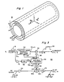
- main magnet 11 has a central cylindrical bore 11a in which is generated a static magnetic field B0, typically in the axial, or Z Cartesian coordinate direction.
- the set of coils 12, such as 3 coils 12-1 to 12-3, receiving electrical signals via input connections 12a, provides at least one gradient magnetic field G within the volume of bore 11.
- a RF coil 14 receiving RF energy via at least one input cable 14a, to provide a RF magnetic field B1, typically in the X-Y plane.
- MRI NMR imaging
- a 90° slice-selective pulse signal is utilized in many MRI procedures.
- the pulse signal consists of a magnetic field gradient G portion 16 and a RF magnetic field B1 portion 18, which is present while the substantially-constant amplitude portion 16a of the gradient pulse is generated, between initial time t0 and time t1.
- the RF magnetic field pulse 18 can be of any selected shape, such as the truncated sin(x)/x RF signal pulse 18 shown, with its reduced-amplitude precedent and subsequent lobes 18a/18b.
- the RF pulse signal has a substantially constant (substantially zero-amplitude) portion 18c after time t1; the gradient magnetic field G pulse requires a finite time (from time t1 to time t2) to return to zero, with trailing edge 16b; the actual slice-selection gradient portion 16 may be followed by a compensation portion 20, of opposite amplitude, and with leading edge 20a (ending at time t3) leading into a substantially constant amplitude portion 20b (ending at time t4), and followed by a trailing edge 20c (ending at time t5 when the zero-amplitude portion 20d is reached).
- the excited transverse magnetization has a normalized amplitude (M tr /M0) with respect to position which is a relatively narrow spatial slice 22 ( Figure 1b) and has a phase ⁇ versus position function 24 as shown in Figure 1c.
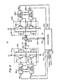
- Switch-mode power amplifier 30 has first and second outputs 30a and 30b between which an existing one of gradient coils 12 is connected.
- the gradient magnetic field G of coil 12 is formed responsive to a flow of a gradient current I g therethrough, which current is responsive to the presence of an input signal, at input 30c, and an enable-gate signal at another input 30d.
- the input and gate signals are provided to separate inputs 34a and 34b, respectively, of a drive means 34, which may also receive a feedback signal, at an input 34c, from a current-monitoring sensor 36.
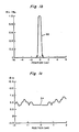
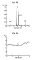
- a ripple amplitude typically on the order of 1% to 10% of the total gradient amplitude, is provided in the pulse top portion 16a′ of the slice selection gradient signal pulse 16′ ( Figure 2a).
- the ripple acts to produce modulation sidebands 44a and 44b ( Figure 2b) at spatial positions removed from the central slice-selective profile 22′; the spatial sidebands are located away from central pulse 22′ by a distance proportional to the ripple frequency (e.g. 20 cycles over 1.2 milliseconds). It is the deleterious sidebands 44 in the spatial profile which provides undesired aliasing responses which must be removed.
- the deleterious aliasing-spatial-sideband effects of amplitude ripple upon the gradient magnetic field signal pulse of a slice-selective pulse signal is removed by modulating the RF magnetic field B1 signal to cause the effective field vector to point in the same direction, throughout the pulse trajectory, as the field vector would point in the normal (non-ripple) pulse.
- the amplitude of the RF waveform signal is modulated with the same ripple as the magnetic field gradient signal, so that the amplitude of the effective field vector is still also modulated, but does not have a noticeable effect on the relative transverse magnetization profile for ripple amplitudes less than about 20%. If absolute control over the gradient waveform were provided, then the phase and duration of the time increments of the pulse could be varied to compensate for the changing amplitude of the effective field vector, to result in an exact compensation on resonance.
- Apparatus 50 operates with switch-mode gradient power amplifier 30, and an existing RF power amplifier 52.
- the flat-topped gradient drive signal pulse 16 is applied to the input 30c of the gradient amplifier to provide the desired gradient coil current I g flowing from the output thereof, with waveform 56 having the undesired ripple at the top of the signal pulse.
- the amplitude of the gradient coil current pulse 56 is sensed by current sensor 36, which provides (with optional amplification and/or processing in means 36′) a sampled gradient current signal I g ′.
- This signal is fed back to the gradient amplifier feedback input 30f and is further applied to the signal input 58a of a variable attenuator means 58.
- the output 58b of the variable attenuator means 58 provides a normalized gradient output signal, of amplitude determined by the amplitude of a control XTRL signal at a control input 58c.
- the normalized gradient signal can be applied directly, or through a variable-phase-setting means 60, to a first input 62a of a RF modulation means 62.
- Modulation means 62 has a second input 62b receiving the input RF signal pulse 18; additional RF amplification means 64 may be utilized.
- the phase-adjusted, normalized-amplitude gradient ripple signal modulates the RF signal and the ripple-modulated RF signal appears at a modulation means output 62c, for amplification in power amplifier PA means 52, to provide a ripple-modulated RF power signal pulse 66 for application to RF coil 14.
- the variable-attenuator control XTRL signal is provided at the output of a full-wave rectifier (FWR) means 48, which receives the gradient input signal pulse 16; additional amplification of the gradient signal pulse 16 may be provided by amplifier means 70, if required.
- FWR full-wave rectifier
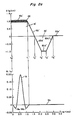
- the switch-mode power amplifier 30 causes the slice selection gradient signal pulse 16′ to have a pulse top portion 16a" with an amplitude ripple 56′, the amplitude of the RF signal pulse 66, and its sidelobes 66a/66b (if any), is modulated with a ripple portion 66′ of controlled amplitude and phase.
- the RF signal amplitude causes a tip angle of 90° (shown) or less, or is even large enough to cause a 180° tip for inversion or refocusing.
- the attenuation applied to the ripple signal I g ′ is proportional to the amplitude of the commanded (desired) gradient signal; the use of a full-wave rectifier means insures that the amplitude attenuation is independent of the gradient signal pulse polarity.
- circuit delays are sufficiently small, relative to the ripple period, so that no significant phase shift is introduced between the gradient and RF ripple waveforms, and phase shift means 60 may not be required. If the ripple delay is, in fact, sufficiently small, the modulated RF magnetic field will in fact cause the affected field vector to be maintained in the same direction throughout the pulse trajectory as that field vector would point in a non-ripple gradient pulse situation.
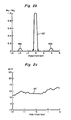
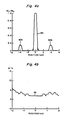
- the resulting normalized spatial magnetization profile 75 is shown in Figure 3b; note that the deleterious spatial-aliasing sidebands 76a/76b are of substantially zero amplitude. An acceptable phase function (Figure 3c) is achieved.
- the normalized spatial magnetization profile has the desired central slice-selective peak 80, but aliasing sidebands 82a and 82b are present.
- the amplitude of undesired sidebands 82a and 82b could be as much as twice the amplitude of the sidebands 44a/44b ( Figure 2b) provided without modulation of the RF signal, i.e. in the original situation.
- provision for the variable phasing means 60 is desirable, and adjustment thereof may be required for a particular configuration of apparatus 50 (as by preliminary imaging of a phantom object) to minimize the spatial sidebands and thus minimize aliasing artifacts.
Landscapes
- Physics & Mathematics (AREA)
- Condensed Matter Physics & Semiconductors (AREA)
- General Physics & Mathematics (AREA)
- Radiology & Medical Imaging (AREA)
- General Health & Medical Sciences (AREA)
- Nuclear Medicine, Radiotherapy & Molecular Imaging (AREA)
- Health & Medical Sciences (AREA)
- Engineering & Computer Science (AREA)
- Signal Processing (AREA)
- High Energy & Nuclear Physics (AREA)
- Magnetic Resonance Imaging Apparatus (AREA)
- Image Processing (AREA)
- Image Analysis (AREA)
Applications Claiming Priority (2)
| Application Number | Priority Date | Filing Date | Title |
|---|---|---|---|
| US07/489,124 US5027071A (en) | 1990-03-05 | 1990-03-05 | Method of, and apparatus for, NMR slice selection |
| US489124 | 1990-03-05 |
Publications (1)
| Publication Number | Publication Date |
|---|---|
| EP0445960A1 true EP0445960A1 (de) | 1991-09-11 |
Family
ID=23942509
Family Applications (1)
| Application Number | Title | Priority Date | Filing Date |
|---|---|---|---|
| EP91301603A Ceased EP0445960A1 (de) | 1990-03-05 | 1991-02-27 | NMR-Abbildung |
Country Status (3)
| Country | Link |
|---|---|
| US (1) | US5027071A (de) |
| EP (1) | EP0445960A1 (de) |
| JP (1) | JPH0618562B2 (de) |
Cited By (2)
| Publication number | Priority date | Publication date | Assignee | Title |
|---|---|---|---|---|
| EP1353192A2 (de) | 2002-04-09 | 2003-10-15 | Esaote S.p.A. | Verfahren und Gerät zur Kompensierung von magnetischen Rauschfeldern in räumlichen Volumina und Kernspintomograph |
| EP0797290B1 (de) * | 1996-03-23 | 2006-05-03 | Siemens Magnet Technology Limited | Geregelter Resonanzwandler |
Families Citing this family (7)
| Publication number | Priority date | Publication date | Assignee | Title |
|---|---|---|---|---|
| NL9100138A (nl) * | 1991-01-28 | 1992-08-17 | Philips Nv | Magnetische resonantie werkwijze en inrichting ter reductie van beeldfouten in een magnetisch resonantiebeeld. |
| US6930483B2 (en) * | 2003-08-01 | 2005-08-16 | General Electric Company | Method/system for switched frequency ripple reduction in MRI gradient coils |
| EP2933225A1 (de) * | 2004-07-23 | 2015-10-21 | The Regents of The University of California | Metamaterialien |
| US20070031156A1 (en) * | 2005-07-29 | 2007-02-08 | Robotham W S Jr | Amplification of TTL RF oscillator signals with digital logic and power switching technology for CO2 laser RF power supplies |
| US9594144B2 (en) | 2014-04-23 | 2017-03-14 | General Electric Company | Low-noise magnetic resonance imaging using low harmonic pulse sequences |
| US10634744B2 (en) | 2017-09-19 | 2020-04-28 | General Electric Company | Magnetic resonance imaging gradient driver systems and methods |
| US10557901B2 (en) * | 2018-02-21 | 2020-02-11 | General Electric Company | Systems and methods for providing gradient power for an MRI system |
Citations (2)
| Publication number | Priority date | Publication date | Assignee | Title |
|---|---|---|---|---|
| GB2041537A (en) * | 1979-01-25 | 1980-09-10 | Emi Ltd Nmr | Improvements in or relating to NMR imaging systems |
| EP0240319A2 (de) * | 1986-03-31 | 1987-10-07 | Kabushiki Kaisha Toshiba | Bilderzeugungssystem mittels magnetischer Resonanz |
Family Cites Families (1)
| Publication number | Priority date | Publication date | Assignee | Title |
|---|---|---|---|---|
| IL86231A (en) * | 1988-04-29 | 1991-07-18 | Elscint Ltd | Correction for eddy current caused phase degradation |
-
1990
- 1990-03-05 US US07/489,124 patent/US5027071A/en not_active Expired - Lifetime
-
1991
- 1991-02-27 EP EP91301603A patent/EP0445960A1/de not_active Ceased
- 1991-02-28 JP JP3055629A patent/JPH0618562B2/ja not_active Expired - Lifetime
Patent Citations (2)
| Publication number | Priority date | Publication date | Assignee | Title |
|---|---|---|---|---|
| GB2041537A (en) * | 1979-01-25 | 1980-09-10 | Emi Ltd Nmr | Improvements in or relating to NMR imaging systems |
| EP0240319A2 (de) * | 1986-03-31 | 1987-10-07 | Kabushiki Kaisha Toshiba | Bilderzeugungssystem mittels magnetischer Resonanz |
Cited By (4)
| Publication number | Priority date | Publication date | Assignee | Title |
|---|---|---|---|---|
| EP0797290B1 (de) * | 1996-03-23 | 2006-05-03 | Siemens Magnet Technology Limited | Geregelter Resonanzwandler |
| EP1353192A2 (de) | 2002-04-09 | 2003-10-15 | Esaote S.p.A. | Verfahren und Gerät zur Kompensierung von magnetischen Rauschfeldern in räumlichen Volumina und Kernspintomograph |
| EP1353192A3 (de) * | 2002-04-09 | 2004-07-14 | Esaote S.p.A. | Verfahren und Gerät zur Kompensierung von magnetischen Rauschfeldern in räumlichen Volumina und Kernspintomograph |
| US6844732B2 (en) | 2002-04-09 | 2005-01-18 | Esaote S.P.A. | Method and device for compensating for magnetic noise fields in spatial volumes, and nuclear magnetic resonance imaging apparatus |
Also Published As
| Publication number | Publication date |
|---|---|
| JPH0618562B2 (ja) | 1994-03-16 |
| US5027071A (en) | 1991-06-25 |
| JPH04220237A (ja) | 1992-08-11 |
Similar Documents
| Publication | Publication Date | Title |
|---|---|---|
| US4585995A (en) | Nuclear magnetic resonance eddy field suppression apparatus | |
| US5471140A (en) | Magnetic field generating assembly | |
| US7183770B2 (en) | High-frequency system for an MR apparatus with multiple transmit channels | |
| US5227728A (en) | Gradient driver control in magnetic resonance imaging | |
| US5027071A (en) | Method of, and apparatus for, NMR slice selection | |
| CN101297212A (zh) | Mri中发射器的主动去耦 | |
| US6362623B1 (en) | Gradient coil for MRI apparatus using shielding coil disposed in a high winding density zone | |
| US6154030A (en) | Digital eddy current compensation | |
| EP1570285A1 (de) | Magnetresonanzabbildungssystem mit mehreren sendespulen | |
| GB2366387A (en) | Electron paramagnetic resonance imaging device using microwave bridge translator | |
| US6777939B2 (en) | Coil system with current regulation based on emitted heat | |
| US5675256A (en) | Magnetic resonance methods and apparatus | |
| KR100413904B1 (ko) | 자기 공명 촬상용 여기 방법과 원자핵 스핀 여기 장치 및 자기 공명 촬상 장치 | |
| US6510035B2 (en) | Coil driving method, coil driving apparatus and MRI apparatus | |
| US4862084A (en) | Method and system for controlling characteristics of gradient magnetic fields in magnetic resonance imaging apparatus | |
| US4549138A (en) | Apparatus and method for examining an object by nuclear magnetic resonance | |
| DE102020211606A1 (de) | Verfahren und Vorrichtung zur Unterdrückung von Störemissionen in Magnetresonanzsystemen | |
| JPH03210237A (ja) | 磁気共鳴装置 | |
| JPH05277087A (ja) | 室温のシムコイルとの勾配コイル相互作用を減じるための方法及び装置 | |
| JP3112866B2 (ja) | Mrイメージング方法およびmri装置 | |
| JP3337712B2 (ja) | 磁気共鳴イメージング装置 | |
| DE102020211602A1 (de) | Vorrichtung und Verfahrten zur frequenzkompensierten Störunterdrückung in Magnetresonanzsystemen | |
| US12504492B2 (en) | System including magnetic resonance tomography units operated with limited bandwidth | |
| JPH0670903A (ja) | Mri装置 | |
| WO2004008169A1 (en) | Mr method utilizing multi-dimensional rf pulses |
Legal Events
| Date | Code | Title | Description |
|---|---|---|---|
| PUAI | Public reference made under article 153(3) epc to a published international application that has entered the european phase |
Free format text: ORIGINAL CODE: 0009012 |
|
| AK | Designated contracting states |
Kind code of ref document: A1 Designated state(s): DE FR GB NL |
|
| 17P | Request for examination filed |
Effective date: 19911220 |
|
| 17Q | First examination report despatched |
Effective date: 19950119 |
|
| GRAG | Despatch of communication of intention to grant |
Free format text: ORIGINAL CODE: EPIDOS AGRA |
|
| STAA | Information on the status of an ep patent application or granted ep patent |
Free format text: STATUS: THE APPLICATION HAS BEEN REFUSED |
|
| 18R | Application refused |
Effective date: 19960803 |