EP0445989B1 - Flüssigkeitsreinigungszubehör mit Druckbeaufschlagungskolben - Google Patents
Flüssigkeitsreinigungszubehör mit Druckbeaufschlagungskolben Download PDFInfo
- Publication number
- EP0445989B1 EP0445989B1 EP91301738A EP91301738A EP0445989B1 EP 0445989 B1 EP0445989 B1 EP 0445989B1 EP 91301738 A EP91301738 A EP 91301738A EP 91301738 A EP91301738 A EP 91301738A EP 0445989 B1 EP0445989 B1 EP 0445989B1
- Authority
- EP
- European Patent Office
- Prior art keywords
- liquid
- piston
- cylinder
- container
- cylinder chamber
- Prior art date
- Legal status (The legal status is an assumption and is not a legal conclusion. Google has not performed a legal analysis and makes no representation as to the accuracy of the status listed.)
- Expired - Lifetime
Links
- 239000007788 liquid Substances 0.000 title claims description 203
- 239000003570 air Substances 0.000 claims description 68
- 239000012510 hollow fiber Substances 0.000 claims description 31
- 239000012080 ambient air Substances 0.000 claims description 16
- 238000011144 upstream manufacturing Methods 0.000 claims description 16
- 239000012982 microporous membrane Substances 0.000 claims description 15
- 239000012530 fluid Substances 0.000 claims description 14
- 238000001914 filtration Methods 0.000 claims description 11
- 238000004891 communication Methods 0.000 claims description 9
- 238000005192 partition Methods 0.000 claims description 9
- 229920001971 elastomer Polymers 0.000 claims description 7
- 239000011148 porous material Substances 0.000 claims description 7
- 239000013013 elastic material Substances 0.000 claims description 3
- 230000002401 inhibitory effect Effects 0.000 claims description 3
- 241000894006 Bacteria Species 0.000 description 11
- 239000002245 particle Substances 0.000 description 8
- 239000000835 fiber Substances 0.000 description 6
- 238000007789 sealing Methods 0.000 description 6
- 238000004140 cleaning Methods 0.000 description 5
- 238000010276 construction Methods 0.000 description 5
- 239000000463 material Substances 0.000 description 5
- 229920000098 polyolefin Polymers 0.000 description 5
- 230000002829 reductive effect Effects 0.000 description 5
- 239000002689 soil Substances 0.000 description 5
- XLYOFNOQVPJJNP-UHFFFAOYSA-N water Substances O XLYOFNOQVPJJNP-UHFFFAOYSA-N 0.000 description 5
- 241000700605 Viruses Species 0.000 description 4
- 238000000034 method Methods 0.000 description 4
- 239000000356 contaminant Substances 0.000 description 3
- 239000003651 drinking water Substances 0.000 description 3
- 235000020188 drinking water Nutrition 0.000 description 3
- 239000000428 dust Substances 0.000 description 3
- 239000008223 sterile water Substances 0.000 description 3
- 206010052428 Wound Diseases 0.000 description 2
- 208000027418 Wounds and injury Diseases 0.000 description 2
- 239000007864 aqueous solution Substances 0.000 description 2
- POIUWJQBRNEFGX-XAMSXPGMSA-N cathelicidin Chemical compound C([C@@H](C(=O)N[C@@H](CCCNC(N)=N)C(=O)N[C@@H](CCCCN)C(=O)N[C@@H](CO)C(=O)N[C@@H](CCCCN)C(=O)N[C@@H](CCC(O)=O)C(=O)N[C@@H](CCCCN)C(=O)N[C@@H]([C@@H](C)CC)C(=O)NCC(=O)N[C@@H](CCCCN)C(=O)N[C@@H](CCC(O)=O)C(=O)N[C@@H](CC=1C=CC=CC=1)C(=O)N[C@@H](CCCCN)C(=O)N[C@@H](CCCNC(N)=N)C(=O)N[C@@H]([C@@H](C)CC)C(=O)N[C@@H](C(C)C)C(=O)N[C@@H](CCC(N)=O)C(=O)N[C@@H](CCCNC(N)=N)C(=O)N[C@@H]([C@@H](C)CC)C(=O)N[C@@H](CCCCN)C(=O)N[C@@H](CC(O)=O)C(=O)N[C@@H](CC=1C=CC=CC=1)C(=O)N[C@@H](CC(C)C)C(=O)N[C@@H](CCCNC(N)=N)C(=O)N[C@@H](CC(N)=O)C(=O)N[C@@H](CC(C)C)C(=O)N[C@@H](C(C)C)C(=O)N1[C@@H](CCC1)C(=O)N[C@@H](CCCNC(N)=N)C(=O)N[C@@H]([C@@H](C)O)C(=O)N[C@@H](CCC(O)=O)C(=O)N[C@@H](CO)C(O)=O)NC(=O)[C@H](CC=1C=CC=CC=1)NC(=O)[C@H](CC(O)=O)NC(=O)CNC(=O)[C@H](CC(C)C)NC(=O)[C@@H](N)CC(C)C)C1=CC=CC=C1 POIUWJQBRNEFGX-XAMSXPGMSA-N 0.000 description 2
- 230000000249 desinfective effect Effects 0.000 description 2
- 230000002209 hydrophobic effect Effects 0.000 description 2
- 244000005700 microbiome Species 0.000 description 2
- 229910000838 Al alloy Inorganic materials 0.000 description 1
- 241000702673 Bovine rotavirus Species 0.000 description 1
- 241000589539 Brevundimonas diminuta Species 0.000 description 1
- 241000991587 Enterovirus C Species 0.000 description 1
- 241000700721 Hepatitis B virus Species 0.000 description 1
- 239000004952 Polyamide Substances 0.000 description 1
- 239000004372 Polyvinyl alcohol Substances 0.000 description 1
- 239000000853 adhesive Substances 0.000 description 1
- 230000001070 adhesive effect Effects 0.000 description 1
- 229920002301 cellulose acetate Polymers 0.000 description 1
- 239000003814 drug Substances 0.000 description 1
- 229940079593 drug Drugs 0.000 description 1
- 239000011521 glass Substances 0.000 description 1
- 230000002452 interceptive effect Effects 0.000 description 1
- 239000011499 joint compound Substances 0.000 description 1
- 239000004006 olive oil Substances 0.000 description 1
- 235000008390 olive oil Nutrition 0.000 description 1
- 238000012856 packing Methods 0.000 description 1
- 230000002093 peripheral effect Effects 0.000 description 1
- 239000004033 plastic Substances 0.000 description 1
- 229920003023 plastic Polymers 0.000 description 1
- 229920003229 poly(methyl methacrylate) Polymers 0.000 description 1
- 229920002492 poly(sulfone) Polymers 0.000 description 1
- 229920002239 polyacrylonitrile Polymers 0.000 description 1
- 229920002647 polyamide Polymers 0.000 description 1
- 229920000642 polymer Polymers 0.000 description 1
- 239000004926 polymethyl methacrylate Substances 0.000 description 1
- 229920005749 polyurethane resin Polymers 0.000 description 1
- 229920002451 polyvinyl alcohol Polymers 0.000 description 1
- 230000002441 reversible effect Effects 0.000 description 1
- 239000004576 sand Substances 0.000 description 1
- 239000000243 solution Substances 0.000 description 1
- 239000007921 spray Substances 0.000 description 1
- 230000001954 sterilising effect Effects 0.000 description 1
- 229920003002 synthetic resin Polymers 0.000 description 1
- 239000000057 synthetic resin Substances 0.000 description 1
- 241000712461 unidentified influenza virus Species 0.000 description 1
Images




Classifications
-
- C—CHEMISTRY; METALLURGY
- C02—TREATMENT OF WATER, WASTE WATER, SEWAGE, OR SLUDGE
- C02F—TREATMENT OF WATER, WASTE WATER, SEWAGE, OR SLUDGE
- C02F1/00—Treatment of water, waste water, or sewage
- C02F1/001—Processes for the treatment of water whereby the filtration technique is of importance
- C02F1/002—Processes for the treatment of water whereby the filtration technique is of importance using small portable filters for producing potable water, e.g. personal travel or emergency equipment, survival kits, combat gear
-
- B—PERFORMING OPERATIONS; TRANSPORTING
- B01—PHYSICAL OR CHEMICAL PROCESSES OR APPARATUS IN GENERAL
- B01D—SEPARATION
- B01D35/00—Filtering devices having features not specifically covered by groups B01D24/00 - B01D33/00, or for applications not specifically covered by groups B01D24/00 - B01D33/00; Auxiliary devices for filtration; Filter housing constructions
- B01D35/02—Filters adapted for location in special places, e.g. pipe-lines, pumps, stop-cocks
- B01D35/027—Filters adapted for location in special places, e.g. pipe-lines, pumps, stop-cocks rigidly mounted in or on tanks or reservoirs
-
- B—PERFORMING OPERATIONS; TRANSPORTING
- B01—PHYSICAL OR CHEMICAL PROCESSES OR APPARATUS IN GENERAL
- B01D—SEPARATION
- B01D61/00—Processes of separation using semi-permeable membranes, e.g. dialysis, osmosis or ultrafiltration; Apparatus, accessories or auxiliary operations specially adapted therefor
- B01D61/14—Ultrafiltration; Microfiltration
- B01D61/18—Apparatus therefor
-
- B—PERFORMING OPERATIONS; TRANSPORTING
- B01—PHYSICAL OR CHEMICAL PROCESSES OR APPARATUS IN GENERAL
- B01D—SEPARATION
- B01D63/00—Apparatus in general for separation processes using semi-permeable membranes
- B01D63/02—Hollow fibre modules
- B01D63/024—Hollow fibre modules with a single potted end
- B01D63/0241—Hollow fibre modules with a single potted end being U-shaped
-
- B—PERFORMING OPERATIONS; TRANSPORTING
- B05—SPRAYING OR ATOMISING IN GENERAL; APPLYING FLUENT MATERIALS TO SURFACES, IN GENERAL
- B05B—SPRAYING APPARATUS; ATOMISING APPARATUS; NOZZLES
- B05B9/00—Spraying apparatus for discharge of liquids or other fluent material, without essentially mixing with gas or vapour
- B05B9/03—Spraying apparatus for discharge of liquids or other fluent material, without essentially mixing with gas or vapour characterised by means for supplying liquid or other fluent material
- B05B9/04—Spraying apparatus for discharge of liquids or other fluent material, without essentially mixing with gas or vapour characterised by means for supplying liquid or other fluent material with pressurised or compressible container; with pump
- B05B9/08—Apparatus to be carried on or by a person, e.g. of knapsack type
- B05B9/0805—Apparatus to be carried on or by a person, e.g. of knapsack type comprising a pressurised or compressible container for liquid or other fluent material
- B05B9/0811—Apparatus to be carried on or by a person, e.g. of knapsack type comprising a pressurised or compressible container for liquid or other fluent material comprising air supplying means actuated by the operator to pressurise or compress the container
- B05B9/0816—Apparatus to be carried on or by a person, e.g. of knapsack type comprising a pressurised or compressible container for liquid or other fluent material comprising air supplying means actuated by the operator to pressurise or compress the container the air supplying means being a manually actuated air pump
- B05B9/0822—Apparatus to be carried on or by a person, e.g. of knapsack type comprising a pressurised or compressible container for liquid or other fluent material comprising air supplying means actuated by the operator to pressurise or compress the container the air supplying means being a manually actuated air pump a discharge device being fixed to the container
-
- B—PERFORMING OPERATIONS; TRANSPORTING
- B01—PHYSICAL OR CHEMICAL PROCESSES OR APPARATUS IN GENERAL
- B01D—SEPARATION
- B01D2313/00—Details relating to membrane modules or apparatus
- B01D2313/18—Specific valves
-
- B—PERFORMING OPERATIONS; TRANSPORTING
- B01—PHYSICAL OR CHEMICAL PROCESSES OR APPARATUS IN GENERAL
- B01D—SEPARATION
- B01D2313/00—Details relating to membrane modules or apparatus
- B01D2313/20—Specific housing
- B01D2313/201—Closed housing, vessels or containers
-
- B—PERFORMING OPERATIONS; TRANSPORTING
- B01—PHYSICAL OR CHEMICAL PROCESSES OR APPARATUS IN GENERAL
- B01D—SEPARATION
- B01D2313/00—Details relating to membrane modules or apparatus
- B01D2313/24—Specific pressurizing or depressurizing means
-
- B—PERFORMING OPERATIONS; TRANSPORTING
- B01—PHYSICAL OR CHEMICAL PROCESSES OR APPARATUS IN GENERAL
- B01D—SEPARATION
- B01D2315/00—Details relating to the membrane module operation
- B01D2315/06—Submerged-type; Immersion type
-
- C—CHEMISTRY; METALLURGY
- C02—TREATMENT OF WATER, WASTE WATER, SEWAGE, OR SLUDGE
- C02F—TREATMENT OF WATER, WASTE WATER, SEWAGE, OR SLUDGE
- C02F1/00—Treatment of water, waste water, or sewage
- C02F1/44—Treatment of water, waste water, or sewage by dialysis, osmosis or reverse osmosis
Definitions
- the present invention relates to a liquid purifying attachment which is installed on or attached to a container that accommodates a certain liquid therein, and which is capable of delivering or dispensing the liquid while removing undesired particulate matters, such as soil particles, dust, microorganisms, bacteria, and virus.
- the invention is concerned with such a liquid purifying attachment which is simple and compact in construction, and which may be handled or manipulated with ease.
- liquid purifying devices as disclosed in laid-open Publication Nos. 62-125804 and 62-90706 of unexamined Japanese Patent Application and unexamined Japanese Utility Model Application, respectively.
- These devices use a container for accommodating a liquid, and a micro-porous membrane disposed in a liquid delivery path.
- the container is formed of a suitable elastic material so that the container body is elastically contracted by squeezing hand pressure, to deliver the liquid, and is elastically restored to its original shape upon releasing of the hand pressure.
- the micro-porous membrane permits the liquid to flow therethrough but inhibits passage of undesired particles or bacteria therethrough.
- the bacteria for example, contained in the liquid are removed or filtered out by the micro-porous membrane provided in the liquid delivery path, when the liquid is delivered or dispensed from the container.
- the thus constructed liquid purifying device is not able to employ an elastically non-deformable or non-yieldable or relatively rigid container, such as a canteen formed of hard plastics, aluminum alloys, or other hard material, or a pressure-intolerant glass bottle containing a pharmaceutical liquid.
- an elastically non-deformable or non-yieldable or relatively rigid container such as a canteen formed of hard plastics, aluminum alloys, or other hard material, or a pressure-intolerant glass bottle containing a pharmaceutical liquid.
- the proposed device has some room for improvements.
- the liquid purifying device when carried over in the outdoors for providing sterile water or emergency drinking water, for example, the device is required to be compact and handy to carry, while assuring excellent durability.
- the features of the first part of claim 1 are disclosed in US-A-4714550.
- the present invention was made in view of the prior art situations described above. It is accordingly an object of the invention to provide a liquid purifying attachment which is suitably installed on or attached to a pressure-intolerant, elastically non-deformable or relatively rigid container formed of a hard material, for purifying a liquid accommodated in the container, and which is simple and compact in construction and highly durable.
- the present invention provides a liquid purifying attachment for attachment to a bottleneck of a container, as set out in claim 1.
- the liquid purifying attachment constructed according to the present invention is adapted to be attached to a container which accommodates a mass of a liquid therein.
- a container which accommodates a mass of a liquid therein.
- the container body need not be elastically contracted by squeezing hand pressure, to deliver the liquid out of the container, since the relatively higher pressure required for delivering the liquid can be easily obtained by the reciprocating movements of the piston.
- the present attachment may be considerably suitable for use with a pressure-intolerant, rigid or elastically non-deformable container made of a hard material.
- the present liquid purifying attachment may be made simple and compact in construction, since the liquid delivery path extends through the inner bores in the cylinder and piston, and is thereby protected by these members. Accordingly, the present attachment may be suitably used with a relatively small-sized container, and is considerably handy to carry in the open air, for example.
- the liquid delivery path may include: (a) an upstream liquid passage formed through a bottom wall of the cylinder, such that the upstream liquid passage is open at one end thereof for communication with the mass of liquid in the container, and located at the other end in the cylinder chamber; (b) a downstream liquid passage extending through the piston, such that the downstream liquid passage is open at one end thereof to the exterior space, and located at the other end in the cylinder chamber; and (c) a variable-length connecting passage disposed in the cylinder chamber, for connecting the upstream and downstream liquid passages with each other, while allowing for reciprocating movements of the piston in the cylinder chamber.
- the cylinder may include an inner tube portion which protrudes from a bottom wall of the cylinder into the cylinder bore of the cylinder.
- the piston is fluid-tightly fitted on an outer circumferential surface of the inner tube portion such that the piston is longitudinally slidable relative to the inner tube portion, so that the inner tube portion extends through the cylinder chamber and an inner bore of the piston.
- the above-indicated liquid delivery path is formed within and defined by the inner tube portion of the cylinder.
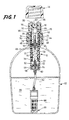
- FIG. 1 which shows a liquid purifying attachment of one embodiment of the invention as installed for use on a container 22
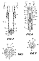
- reference numeral 10 denotes a cylinder having a generally cylindrical shape which is open at one end thereof and closed at the other end. More specifically described referring also to Figs. 2 and 3, the cylinder 10 has a cylinder bore 12 which is open at one longitudinal end thereof, and is formed at the open end integrally with an annular mounting portion 14 having an internally threaded inner surface. On an end face of the mounting portion 14, there are formed a pair of protection walls 16, 16 as integral parts of the cylinder 10.
- the protection walls 16 have a generally arcuate shape as viewed in transverse cross section of Fig. 3, and extend axially (longitudinally) outwardly from the open end of the cylinder 10.
- the protection walls 16 are externally threaded, for engagement with an internally threaded cap 18, so that the opening of the cylinder 10 is closed by the cap 18.
- the container 22 in the form of a bottle accommodates a mass of a desired liquid 20.
- the cylinder 10 is inserted through an opening of an externally threaded cylindrical bottleneck 24 formed at the upper end of the container 22, and is threaded or screwed at the mounting portion 14 on the bottleneck 24 of the container 22, such that the lower part of the cylinder 10 is accommodated in the container 22.
- the opening of the bottleneck 24 of the container 22 is pressure- or fluid-tightly closed by the cylinder 10 thus mounted on the container 22.
- the cylinder bore 12 of the cylinder 10 receives a piston 26 having an outside diameter substantially equal to the diameter of the bore 12, such that the piston 26 is axially slidably reciprocable within the cylinder 10.
- the piston 26 has a cylindrical portion 28 which is closed at the upper end thereof by a lid 30 secured thereto.
- the piston 26 as a whole is formed as a generally cylindrical member which is closed at the upper end thereof and is open at the lower end, as shown in Figs. 4 and 5.
- the piston 26 is inserted into and disposed in the cylinder bore 12 of the cylinder 10, such that an opening of an inner bore 32 of the piston 26 is located at the lower part of the cylinder bore 12.
- An annular packing 34 is fixed to the open end portion of the piston 26, so that the piston 26 is axially slidable relative to the inner surface of the cylinder 10 while maintaining fluid-tightness between the piston 26 and the cylinder 10.
- the piston 26 is formed at its closed or upper end portion with an annular protrusion 36, which protrudes radially outwardly from the outer circumferential surface of the piston 26.
- This annular protrusion 36 is adapted to abut on the end face of the mounting portion 14 of the cylinder 10, so as to determine the fully retracted position of the piston 26, which is established when the piston 26 is pushed down into the cylinder bore 12.
- the fully retracted position of the piston 26 is determined such that the volume of the cylinder chamber 37 in the cylinder bore 12 is sufficiently large even when the piston 26 is placed in the fully retracted position as described above.
- the lid 30 of the piston 26 has a pair of generally arcuate guiding walls 38, 38 formed so as to extend outwardly from the peripheral portion of the outer surface thereof. These guiding walls 38, 38 are manually- or finger-operated to readily permit the piston 26 to be reciprocated in the cylinder bore 12 of the cylinder 10.
- the piston 26 is provided with a disc-like partition plate 42 secured thereto, which is located in an intermediate portion of the inner bore 32 of the piston 26.
- the interior space of the inner bore 32 is divided by the partition plate 42 into an upper region 44 on the side of the lid 30, and a lower region 46 on the side of the open end of the piston 26.
- the lower region 46 is open to the cylinder bore 12, and thus provides a part of the cylinder chamber 37 formed in the cylinder bore 12.
- the upper region 44 communicates with the ambient air, through an air inlet 40 formed through the cylindrical wall of the piston 26 at its upper portion adjacent to and below the annular protrusion 36.
- the upper region 44 also communicates with the cylinder chamber 37 (lower region 46), through a plurality of through-holes 48 formed through the partition plate 42.
- the partition plate 42 is provided with a first check valve 50 in the form of a thin-walled rubber disc, which is fixed to the lower surface of the partition plate 42 so as to close the open ends of the through holes 48 which are open toward the cylinder chamber 37.
- This first check valve 50 permits a flow of the air from the upper region 44 into the cylinder chamber 37, but inhibits a flow of the air from the cylinder chamber 37 into the upper region 44.
- the pressure in the cylinder chamber 37 is reduced to be lower than the external atmospheric pressure, whereby the ambient air in the exterior space is introduced into the cylinder chamber 37, through the air inlet 40, the upper region 44 and the through-holes 48.
- the air inlet 40, the upper region 44 and the through holes 48 constitute an air inlet passage for introducing the ambient air into the cylinder chamber 37.
- the cylinder chamber 37 including the lower region 46 indicated above communicates with the interior storage space of the container 22, through a plurality of air-feed holes 52 formed through the bottom wall of the cylinder 10.
- a second check valve 54 in the form of a thin-walled rubber disc is fixed to the lower surface of the bottom wall of the cylinder 10 so as to cover and close the open ends of the air-feed holes 52 which are open toward the interior of the container 22.
- This second check valve 54 permits a flow of the air from the cylinder chamber 37 into the interior of the container 22, but inhibits a flow of the air from the interior space of the container 22 into the cylinder chamber 37.
- reference numeral 56 denotes a valve support which is threaded on an annular extension formed on the lower end of the cylinder 10 so as to retain the second check valve 54 in position.
- the air-feed holes 52 formed in the cylinder 10 communicates with the interior space of the container 22, via an annular space 58 defined by the valve support 56 and the annular extension of the cylinder 10.
- the air-feed holes 52 and the annular space 58 constitute a compressed-air supply passage through which the compressed air in the cylinder chamber 37 is fed into the container 22.
- the piston 26 is reciprocatingly moved in the longitudinal direction within the cylinder bore 12, so that the ambient air is sucked into the cylinder chamber 37 through the air inlet passage, and then compressed in the chamber 37, and so that the thus compressed air is fed into the interior space of the container 22, through the compressed-air supply passage. In this manner, the pressure in the interior storage space of the container 22 is elevated.
- the valve support 56 threaded to the lower end of the cylinder 10 has a center hole 60 formed through the radially central portion thereof.
- This center hole 60 is open at one end thereof in the cylinder chamber 37 and at the other end in the interior storage space of the container 22.
- a flexible feed tube 62 which is submerged in the liquid 20 accommodated in the container 22.
- the center hole 60 and the feed tube 62 constitute an upstream liquid passage which is open in the liquid 20 at one end thereof, and is located in the cylinder chamber 37 at the other end.
- a protecting cover 65 which accommodates a micro-porous membrane filter in the form of a hollow or macaroni fiber module 66.
- the hollow fiber module 62 accommodated in the protecting cover 65 includes a U-shaped array of a plurality of hollow fibers 68 each having a micro-porous wall structure, and a header 70 to which the end portions of the U-shaped array consisting of the opposite open ends of the fibers 68 are bonded with a suitable adhesive such as polyurethane resin.
- the module 66 is disposed in the protecting cover 65, with the header 70 fixedly or removably supported by the cover 65.
- the opposite open ends of the micro-porous hollow fibers 68 of the module 66 are open to the feed tube 62 through an enclosed space within the protecting cover 65, such that the enclosed space is fluid-tightly sealed by the header 70 with respect to the liquid mass 20 accommodated in the container 22. Accordingly, the liquid 22 is permitted to flow into the feed tube 62 only through the wall of the hollow fibers 68 of the module 66.
- the micro-porous wall structure of each of the multiple hollow fibers 68 of the module 66 has pores whose diameters are large enough to permit the molecules of the the liquid 20 in the container 22 to pass therethrough, but are small enough to inhibit the passage of soil particles, bacteria or other contaminants (undesired particulate matters) in the liquid 20, thereby filtering out these contaminants.
- the diameters of the pores of the hollow fibers 68 are determined so that the micro-porous structure may remove or trap pseudomonas diminuta ATCC19146. Namely, a typical micro-porous structure of the fibers 68 should prevent the passage of particles having a diameter of 0.2-0.3 ⁇ m.
- the micro-porous structure of the hollow fibers 68 should have smaller pores.
- the diameters of the pores should be determined so as to prevent the passage of particles of at least 0.08 ⁇ m, 0.07 ⁇ m, and 0.025 ⁇ m, for the micro-porous structure to be able to remove influenza virus, Bovinerota virus, and polio virus and/or hepatitis B virus, respectively.
- the micro-porous hollow fibers 68 may be made of high-molecule polymers, preferably, such as polyolefin, polyvinyl alcohol, polysulfone, polyacrylonitrile, cellulose acetate, polymethyl methacrylate and polyamide, by a suitable known method such as micro phase separating method or drawing method.
- the micro-porous hollow fibers made of polyolefin by a drawing technique are preferably used since the polyolefin hollow fibers are highly water-permeable but are highly capable of filtering out minute particles, and have at the same time a relatively high strength. Accordingly, the hollow polyolefin fibers are easily processed into the module 66 and are highly resistant to mechanical stresses during use.
- the micro-porous hollow fibers 68 preferably have a porous structure which exhibits sufficiently high hydrophilic property.
- the hollow fibers should preferably be processed to give the porous structure hydrophilic property.
- the liquid 20 is an olive oil or other oily liquid, it is desirable that the porous hollow fibers 68 exhibit hydrophobic property.
- the partition plate 42 disposed in the inner bore 32 of the piston 26 has a center hole 72 formed through the central portion thereof in the longitudinal direction of the piston 26.
- the center hole 72 is located at one end thereof in the upper region 44 of the bore 32, and at the other end in the cylinder chamber 37 (the lower region 46).
- a dispenser 78 of a push-operated type To the one open end of the center hole 72 located in the upper region 44, there is connected a dispenser 78 of a push-operated type, through a tube 76.
- the dispenser 78 has a fluid passage formed therethrough and through the lid 30 of the piston 26, so that the passage is open to the atmosphere. It will be understood from the above description that the center hole 72, the tube 76 and the fluid passage formed through the dispenser 78 constitute a downstream liquid passage which is open at one end thereof in the cylinder chamber 37, and is open at the other end to the atmosphere.
- the push-operated type dispenser 78 partially defining the downstream liquid passage incorporates a check valve (not shown), and is adapted to dispense liquid under pressure.
- the fluid passage in the dispenser 78 is normally closed, that is, the dispenser 78 is normally placed in its closed position, against the pressure of the liquid 20 flowing through the center hole 72 toward the dispenser 78.
- the dispenser 78 has an operating head 80 fixedly fitted on the upper end portion thereof, as shown in Figs. 1 and 4. This head 80 is finger-operated to place the dispenser 78 in its open position so that the fluid passage in the dispenser 78 communicates with the center hole 72 of the partition plate 42.
- the check valve incorporated in the dispenser 78 serves as third valve means for selectively opening or closing the downstream liquid passage as described above.
- the lower open end of the center hole 72 on the side of the cylinder chamber 37 is connected to the center hole 60 formed through the bottom wall of the cylinder 10, by a connecting tube 74 which is accommodated in the cylinder chamber 37 to define a connecting passage for fluid communication between the center holes 72, 60.
- the connecting tube 74 is formed of an elastic material such as rubber, and is normally folded several times in the cylinder chamber 37 (i.e., in the lower region 46 of the inner bore 32 of the piston 26). Accordingly, when the piston 26 is reciprocatingly moved in the cylinder bore 12 of the cylinder 10, the connecting tube 74 is elastically deformed to permit a change in the distance between the open ends of the center holes 60, 72 connected to the tube 74, while maintaining fluid communication between the central holes 60, 72.
- the upstream liquid passage 60, 62 is connected to and communicates with the downstream liquid passage 72, 76, 78, through the connecting passage defined by the connecting tube 74.
- the present embodiment has a liquid delivery path consisting of these upstream and downstream liquid passages and the connecting tube 74, through which the liquid 20 accommodated in the container 22 is delivered out of the container 22.
- the pressure in the container 22 is elevated by reciprocating the piston 26 in the cylinder bore 12 relative to the cylinder 10, between the fully retracted and fully advanced positions.
- the liquid 20 is delivered out of the container 22 through the above-described liquid delivery path, due to the higher pressure in the interior space of the container 22 than the external atmospheric pressure.
- the instant liquid purifying attachment is capable of filtering or sterilizing the liquid 20 when it passes through the porous hollow fibers 68 of the hollow fiber module 66 connected to the lower open end of the flexible feed tube 62 which partially defines the upstream liquid passage.
- the hollow fibers 68 are adapted to remove undesired particulate matters contained in the liquid 20, such as soil particles, bacteria and virus, depending on the diameters of the pores in the micro-porous wall structure of the hollow fibers 68. It is to be understood that after the required amount of the liquid 20 is delivered out of the container 22, the delivery of the liquid 20 is stopped by releasing a finger pressure from the operating head 80.
- the liquid delivery path through which the liquid 20 flows is normally closed by the check valve disposed in the dispenser 78 while the instant attachment is not in use. Further, while the liquid 20 is being delivered out of the container 22 with the dispenser 78 placed in the open position, the liquid 20 is forced to flow through the open dispenser 78, always in the direction toward the external open end of the liquid delivery path which is open to the atmosphere, due to the higher pressure in the container 22 than the external atmospheric pressure. Namely, in the open position of the dispenser 78, there may arise no flow of the liquid 20 and air in the reverse direction, through the liquid delivery path toward the interior space of the container 22. Accordingly, the liquid delivery path and the hollow fiber module 66 are effectively protected against dust and bacteria which would otherwise enter the instant liquid purifying attachment through the liquid delivery path.
- the liquid 20 is delivered out of the container 22 by utilizing the air pressure which is developed in the container 22 by the reciprocating movements of the piston 26.
- the container 22 may be made of a hard material since the container 22 need not be elastically contracted by squeezing hand pressure, to deliver the liquid.
- the instant liquid purifying attachment having all the necessary functions to purify the liquid is easily attached to the container 22, by simply screwing the mounting portion 14 of the cylinder 10 on the externally threaded cylindrical bottleneck 24 of the container 22.
- This favorably provides significant improvements in ease of handling and carrying of the attachment, and permits easy use of the attachment with high efficiency.
- the liquid delivery path of the instant attachment is formed through the cylinder chamber 37 which is used to compress the air introduced from the exterior of the attachment, and to compress the air in the interior space of the container 22. Since both the compressed-air supply passage for feeding the compressed air into the container 22, and the liquid delivery path for delivering the liquid 20 out of the container 22 are substantially located in the same cylinder 10, the instant liquid purifying attachment may be made compact and small-sized. Accordingly, the instant attachment may be used with a relatively small-sized container, and assures considerably high portability in the outdoors.
- the liquid delivery path formed through the cylinder chamber 37 is effectively protected by the cylinder 10 which surrounds the most part of the path. Accordingly, the instant liquid purifying attachment can be carried from one place to another, without suffering from undesirable damages to the liquid delivery path, assuring a high degree of durability.
- the hollow fiber module 66 which serves as the micro-porous membrane filter for filtering the liquid 20 has a relatively large filtering surface area, since the module 66 consists of an array of the multiple hollow fibers 68. Accordingly, the instant attachment permits a sufficiently large amount of the liquid 20 purified per unit time, i.e., a sufficiently high rate of delivery of the purified liquid 20, even when the liquid 20 is a comparatively viscous liquid. This favorably results in reducing the size of the attachment, and provides improvements in ease of handling or manipulation of the attachment.
- FIGs. 7 through 9 another embodiment of the liquid purifying attachment will be described.
- This embodiment uses a modified form of the air inlet passage through which the air is introduced from the exterior space into the cylinder chamber, and a modified form of the first valve means disposed in the air inlet passage.
- the same reference numerals as used with respect to the preceding embodiment will be used in Figs. 7-9, to identify the functionally corresponding elements, and redundant description of these elements will not be provided.
- the cylindrical portion 28 of the piston 26 has an outside diameter slightly smaller than the inside diameter of the cylinder 10.
- a clearance 82 between the cylindrical portion 28 of the piston 26 and the cylindrical wall of the cylinder 10 which defines the cylinder bore 12.
- an O-ring 86 is fitted in a circumferential groove 84 formed in the outer circumferential surface of the lower open end portion of the piston 26. The O-ring 86 functions to close the clearance 82, to thereby maintain air- or gas-tightness of the cylinder chamber 37.
- the piston 26 has a window 88 formed at a circumferential part of the lower open end portion thereof which provides a bottom wall of the circumferential groove 84.
- the window 88 extends in the radial direction through the thickness of the bottom wall of the groove 84, and communicates with the groove 84 and the inner bore 32 of the piston 26.
- the pressure in the cylinder chamber 37 acts on the O-ring 86 fitted in the groove 84, through the window 88.
- the clearance 82 serves as the air-inlet passage for introducing the ambient air into the cylinder chamber 37
- the O-ring 86 and window 88 serve as the first valve means for permitting a flow of the air from the clearance 82 into the cylinder chamber 37, and for inhibiting a flow of the air from the cylinder chamber 37 into the clearance 82.
- the first valve means is provided by using only the O-ring 86 for securing an air-tight sealing between the outer surface of the piston 26 and the inner surface of the cylindrical wall of the cylinder 10. Accordingly, the present liquid purifying attachment may be made relatively compact and small-sized owing to a reduced number of components required, as compared with the preceding embodiment.
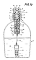
- FIG. 10 shows a further embodiment of the liquid purifying attachment, which employs a connecting passage as a part of liquid delivery path, which passage is different from that of the preceding second embodiment of Figs. 7-9.
- the same reference numerals as used in the second embodiment will be used to identify the corresponding elements, and redundant description thereof will not be provided.
- the present liquid purifying attachment has a cylindrical connecting sleeve 90 which is inserted in the inner bore 32 of the piston 26.
- This connecting sleeve 90 is connected to one open end of the center hole 60 (upstream liquid passage) formed through the valve support 56, which end is located in the cylinder chamber 37.
- the piston 26 is slidably movable in the longitudinal direction thereof relative to the connecting sleeve 90, and thus cooperates with the sleeve 90 to provide a variable-length connecting passage as described below.
- the fluid passage formed through the dispenser 78 is open in the upper closed end portion of the inner bore 32 of the piston 26 which receives the connecting sleeve 90, such that the fluid passage in the dispenser 78 communicates with the inner bore 32.
- the center hole 60 of the valve support 56 as the upstream liquid passage is held in fluid communication with the fluid passage of the dispenser 78 as the downstream liquid passage, through an inner bore of the connecting sleeve 90 and the inner bore 32 of the piston 26.
- the connecting sleeve 90 and the piston 26 which are slidably movable relative to each other cooperate to define the variable-length connecting passage for connecting the upstream and downstream liquid passages, such that the length of the connecting passage is varied upon longitudinal reciprocating movements of the piston 26 within the cylinder bore 12 of the cylinder 10.
- the connecting passage of the liquid delivery path is provided by using the sleeve 90 made of a hard material such as synthetic resin, assuring a comparatively high degree of durability compared to the case where the connecting passage is provided by an elastic member as in the preceding embodiments.
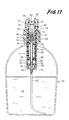
- FIG. 11 a still further embodiment (fourth embodiment) of the liquid purifying attachment will be described.
- This embodiment is similar to the preceding third embodiment, except the position of the hollow fiber module 66 as the micro-porous membrane filter.
- the same reference numerals as used in the third embodiment will be used to identify the corresponding elements, and redundant description thereof will not be provided.
- the hollow fiber module 66 as the micro-porous membrane filter as shown in Fig. 6 is disposed in the upper closed end portion of the inner bore 32 of the piston 26, such that the header 70 for fixing the porous hollow fibers 68 together is fitted in the inner bore 32, and secured to the inner circumferential surface of the piston 26.
- the inner bore 32 of the piston 26 is divided by the header 70 of the fiber module 66 into two fluid-tight sections.
- the liquid 20 which flows into the inner bore 32 of the piston 26 passes through the porous hollow fibers 68 of the fiber module 66, and then flows into the fluid passage of the dispenser 78 as the downstream liquid passage.
- the present liquid purifying attachment may be made more compact or small-sized than the preceding embodiments, without suffering from damages to the module 66. Accordingly, the present attachment may be conveniently or readily carried from one place to another.
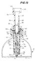
- FIG. 12 through 15 another embodiment (fifth embodiment) of the liquid purifying attachment will be described.
- This embodiment employs a liquid delivery path through which the liquid 20 is delivered out of the container 22, which liquid delivery path is different from those of all the preceding embodiments.
- the same reference numerals as used in the first embodiment will be used to identify the corresponding elements, and redundant description thereof will not be provided.
- reference numeral 100 denotes a cylinder which has a generally cylindrical sleeve 102, and a cap-like member 104 that is fixedly threaded on the lower end portion of the sleeve 102.
- the cylinder 100 has a cylinder bore 106 formed therein, which is open at the upper end of the sleeve 102.
- the sleeve 102 is formed at its upper end portion (on the side of the open end of the cylinder bore 106) with an annular mounting portion 108. With this mounting portion 108 being threaded on the bottleneck 24 of the container 22, the cylinder 100 is installed in place on the container 22.
- reference numerals 110, 112 designate a sealing member provided between the cylinder 100 and the bottleneck 24, and a sealing member provided between the sleeve 102 and the cap-like member 104, respectively.
- the cap-like member 104 of the cylinder 100 has an inner tube 120 fixed thereto, which extends through a central portion of the bottom wall of the member 104, in the longitudinal direction of the cylinder 100.
- This inner tube 120 is located within the cylinder bore 106, such that the inner tube 120 protrudes from the bottom wall of the cap-like member 104 toward the upper open end of the bore 106.
- the cylinder 100 receives a piston 114 slidably in the cylinder bore 106.
- the piston 114 includes a generally cylindrical sleeve 116 which is formed at one open end thereof with a generally annular plate 118.
- the piston 114 is received in the cylinder bore 106, such that the annular plate 118 is located at the lower part of the bore 106 when the piston 114 is in the fully retracted position, and such that the piston 114, more precisely, the annular plate 118 is slidably fitted on the inner tube 120.
- the annular plate 118 is accommodated in the cylinder bore 106 such that the inner and outer circumferential surfaces of the plate 118 is air-tightly slidable with respect to the outer circumferential surface of the inner tube 120 and the inner circumferential surface of the cylinder 100, respectively.
- a cylinder chamber 122 which is air-tightly formed within the cylinder bore 106.
- the piston 114 includes as an integral part thereof a cylindrical larger-diameter head portion 123 formed at the upper open end of the sleeve 116.
- the piston 114 may be reciprocated in the cylinder bore 106 by holding the head portion 123 between one's fingers.
- the head portion 123 is adapted to abut on the upper end face of the cylinder 100, and thereby serves to determine the fully retracted position of the piston 114.
- the annular plate 118 of the piston 114 has a plurality of air inlets 124 formed therethrough, which permits the cylinder chamber 122 to communicate with the ambient air in the exterior space, through an inner bore of the sleeve 116.
- the piston 114 has a first check valve 126 in the form of an annular rubber disc, which is fixed to the lower surface of the annular plate 118 so as to close the open ends of the air inlets 124 which are open to the cylinder chamber 122.
- This first check valve 126 permits a flow of the air from the exterior space into the cylinder chamber 112, but inhibits a flow of the air from the cylinder chamber 112 into the exterior space.
- an air inlet passage of the instant embodiment is constituted by the air inlets 124, and the inner bore of the sleeve 116 which communicates with the air inlets 124 and the exterior space.
- the annular plate 118 and the first check valve 126 are adapted to establish respective air-tight seals between the slidable inner and outer surfaces of the plate 118 and the inner tube 120, and between the slidable outer and inner surfaces of the plate 118 and the cylinder 100.
- the cap-like member 104 of the cylinder 100 has an air-feed hole 128 formed therethrough so as to communicate with the cylinder chamber 122 and the interior storage space of the container 22.
- a second check valve 130 which consists of a thin-walled rubber plate. The second check valve 130 permits a flow of the compressed air from the cylinder chamber 122 into the container 22, but inhibits a flow of the air from the container 22 into the cylinder chamber 122.
- reference numeral 132 denotes a valve support which is secured to the lower surface of the cap-like member 104, and has a central protrusion adapted to press the second check valve 130 against the above-indicated open end of the air-feed hole 128.
- the piston 114 is reciprocatingly moved in the longitudinal direction within the cylinder bore 106, so that the ambient air is sucked into the cylinder chamber 122 through the air inlet passage 116, 124, and compressed in the cylinder chamber 122, and so that the thus compressed air in the chamber 122 is fed to the interior space of the container 22 through the compressed-air supply passage 128.
- the cylinder chamber 122 accommodates two coil springs 134, 134 which are disposed in series with each other. Between these coil springs 134, there is interposed a slider 136 which is slidably fitted on the inner tube 120.
- the piston 114 is biased in the direction away from the bottom wall of the cylinder bore 106, i.e., toward the fully advanced position, under the biasing force of the coil springs 134.
- the piston 114 automatically returns to its fully advanced position in which a substantial portion of the piston 114 protrudes upwards from the open end of the cylinder bore 106, as shown in Fig. 13.
- the piston 114 has an inverted L-shaped groove 138 formed in the outer circumferential surface of the sleeve 116 in the longitudinal direction thereof, as shown in Fig. 15.
- This L-shaped groove 138 consists of a longitudinally extending vertical portion 141, and a terminal portion 142 which extends in the circumferential direction from the upper longitudinal end of the vertical portion 141 on the upper side of the piston 114.
- the sleeve 102 of the cylinder 100 has an integrally formed engaging boss 140 which protrudes from the inner surface of the sleeve 102 into the L-shaped groove 138 formed in the piston 114.
- the piston 114 With the engaging boss 140 slidably engaging the vertical portion 141 of the groove 138, the piston 114 is allowed to be reciprocated in the longitudinal direction relative to the cylinder 100.
- the piston 114 When the piston 114 is not in use, the piston 114 is pushed down to the fully retracted position, and is rotated in the circumferential direction, so that the engaging boss 140 is brought into engagement with the terminal portion 142 of the groove 138.
- the piston 114 is held in its fully retracted position against the biasing force of the coil springs 134.
- the inner tube 120 is fixed to the cylinder 100 so as to protrude into the cylinder bore 106.
- This inner tube 120 has a passage 144 formed therethrough, which communicates with the interior storage space of the container 22 in which the liquid 20 is accommodated, and the exterior space in which the ambient atmosphere is present.
- the flexible feed tube 62 is connected at one end thereof to one open end of the passage 144 on the side of the interior space of the container 22, such that the passage 144 is open in the liquid 20 in the container 22, through the hollow fiber module 66 attached to the other end of the feed tube 62.
- the push-operated type dispenser 78 which includes the third check valve for selectively opening and closing the fluid passage formed therethrough.
- the dispenser 78 is suitably dimensioned such that the dispenser 78 may be accommodated in an inner bore of the sleeve 116 of the piston 114. Further, the dispenser 78 does not protrude from the upper open end of the sleeve 116 (or piston 114) even when the piston 114 is moved to the fully retracted position as shown in Fig. 12. Namely, the dispenser 78 is always located within the inner bore of the sleeve 116, without interfering with the reciprocating movements of the piston 114. With the piston 114 being moved to the fully retracted position, the liquid 20 in the container 20 is delivered from the dispenser 78, through a window 146 formed through the head portion 123 of the sleeve 116.
- the passage 144 extending through the inner tube 120 cooperates with the flexible feed tube 62 and dispenser 78 connected to its opposite ends to constitute a liquid delivery path through which the liquid 20 is delivered out of the container 22.
- the liquid delivery path is defined by a considerably simple structure which does not include a flexible connecting member or other variable-length connecting means as used in the preceding embodiments.
- liquid purifying attachment of the instant embodiment may be produced with high efficiency, at a reduced cost, assuring significantly improved durability.
- the coil springs 134 for biasing the piston 114 in the direction away from the bottom wall of the cylinder 100 facilitate the operation of reciprocating the piston 114 relative to the cylinder 100. This favorably results in an improvement in ease of manipulation of the attachment.
- the piston 26 may be provided with an operating head portion having a proper configuration, other than the guiding walls 38 and the head portion 123 as employed in the illustrated embodiments.
- the piston may include a collapsible or a removable operating head portion.
- the pressure of the compressed air may be utilized as biasing means for biasing the piston 26 in the direction away from the fully retracted position, instead of the coil springs as used in the fifth embodiment.
- the structure for defining the connecting passage is not limited to the connecting tube of a folding type as used in the first embodiment, or the connecting sleeve and the piston which are slidably movable relative to each other as in the second and third embodiments.
- the connecting passage may be defined by any structure which can maintain the fluid communication between the upstream and downstream liquid passages while permitting the longitudinal movement of the piston 26 in the cylinder bore 12 during the operation of the piston 26.
- a bellows type structure, an elastically expandible and contractible tube, a flexible curled, spiral, helical or similarly formed pipe, and various other structures may be employed.
- the flexible feed tube 62 provides a portion of the liquid delivery path which is open in the interior storage space of the container 22.
- the location of the hollow fiber module 66 is not limited to those of the illustrated embodiments, but may be selected as desired along the liquid delivery path.
- micro-porous hollow fibers are used in the illustrated embodiments as a micro-porous membrane filter disposed in the liquid delivery path, for removing bacteria and other contaminants from a flow of the liquid dispensed from the container, other filters such as a planar micro- porous membrane may be used.
- the micro-porous membrane filter used in the invention has pores whose diameters are suitably determined so as to inhibit the passage of undesired matters, such as mud, sand, soil and dust, and microorganisms, bacteria and virus, for assuring sufficient filtering capability depending upon the application or utility of the purified liquid, for example.
- first, second and third valve means are not limited to those of the illustrated embodiments.
- the third valve means may be provided by various other known valves, provided that the valve can be manually placed in its open and closed positions.
- the liquid purifying attachment constructed according to the present invention is capable of dispensing drinking water for use in an emergency, sterile water or liquid that is used for: cleaning hands of people in the open air; cleaning wounds of a body; preparing a drug; cleaning human eyes; cleaning medical goods or facilities or instruments in the open air; and other liquids used in the field of medical treatment.
- the present attachment is also capable of dispensing warm water which is favorably used for cleaning a body of a wounded person (patient).
- the container equipped with the instant liquid purifying attachment is suitably used as a container for dispensing and/or storing a pharmaceutical liquid, for example, as a spray bomb for a sterile disinfecting solution used for disinfecting wounds, or as a feeding or spout cup for a patient.
Landscapes
- Chemical & Material Sciences (AREA)
- Chemical Kinetics & Catalysis (AREA)
- Engineering & Computer Science (AREA)
- Water Supply & Treatment (AREA)
- Life Sciences & Earth Sciences (AREA)
- Hydrology & Water Resources (AREA)
- Environmental & Geological Engineering (AREA)
- Organic Chemistry (AREA)
- Separation Using Semi-Permeable Membranes (AREA)
- Reciprocating Pumps (AREA)
- Closures For Containers (AREA)
Claims (21)
- Flüssigkeitsreinigungszubehör zur Befestigung an einem Flaschenhals eines Behälters zum Abgeben einer im genannten Behälter befindlichen Flüssigkeit, wobei das genannte Zubehör umfaßt:
einen Zylinder (10, 100), der am genannten Flaschenhals des genannten Behälters befestigt ist, um sich teilweise in einen Innenraum des genannten Behälters hinein zu erstrecken und den genannten Innenraum fluiddicht abzuschließen;
einen Kolben (26, 114), der im genannten Zylinder fluiddicht aufgenommen ist, um mit dem genannten Zylinder zusammenzuwirken, um eine Zylinderkammer (37, 122) zu definieren, wobei der genannte Kolben zwischen einer vollständig eingezogenen und einer vollständig ausgefahrenen Position hin- und herbewegbar ist, um Umgebungsluft bei Bewegung des genannten Kolbens zur genannten vollständig ausgefahrenen Position in die genannte Zylinderkammer einzulassen und um die eingeführte Luft in der genannten Zylinderkammer zu komprimieren und bei Bewegung des genannten Kolbens zur genannten vollständig eingezogenen Position in den genannten Innenraum zu leiten;
erste Luftventilmittel (50, 86, 88, 126) zum Ermöglichen des Flusses der genannten Umgebungsluft in die genannte Zylinderkammer und zur Unterbindung des Flusses der genannten komprimierten Luft aus der genannten Zylinderkammer; und
Flüssigkeitsabgabemittel, welche einen Flüssigkeitsabgabeweg (60, 62, 66, 72, 74, 76, 78, 32, 90, 144) definieren, um die genannte Flüssigkeit in Folge des Drucks der genannten komprimierten Luft im genannten Innenraum vom genannten Innenraum aus dem genannten Behälter zu befördern,
wobei die genannten Flüssigkeitsabgabemittel Filtermittel (66) zum Ausfiltern von Fremdkörpern in der genannten Flüssigkeit enthalten, bevor die genannte Flüssigkeit aus dem genannten Behälter abgegeben wird,
dadurch gekennzeichnet, daß zweite Luftventilmittel (54, 130) den Fluß der genannten komprimierten Luft in den genannten Innenraum aus der genannten Zylinderkammer ermöglichen und den Fluß der genannten komprimierten Luft aus dem genannten Innenraum in die genannte Zylinderkammer unterbinden, und daß der genannte Flüssigkeitsabgabeweg zumindest einen Abschnitt enthält, der sich durch die genannte Zylinderkammer und den genannten Kolben hindurch erstreckt. - Flüssigkeitsreinigungszubehör nach Anspruch 1, worin das genannte Flüssigkeitsabgabemittel ein Flüssigkeitsventilmittel (78) enthält, das zwischen einer offenen Position zum Ermöglichen der Abgabe der genannten Flüssigkeit aus dem Behälter und einer geschlossenen Position zum Unterbinden der Abgabe der genannten Flüssigkeit aus dem genannten Behälter händisch betreibbar ist.
- Flüssigkeitsreinigungszubehör nach Anspruch 2, worin das genannte Flüssigkeitsabgabemittel eine Ausgabevorrichtung (78) enthält, welche das genannte Flüssigkeitsventilmittel umfaßt und am genannten Kolben befestigt ist, um zum Betrieb des genannten Flüssigkeitsventilmittels zwischen der genannten offenen und geschlossenen Position den Zugriff darauf zu ermöglichen.
- Flüssigkeitsreinigungszubehör nach einem der Ansprüche 1 bis 3, worin der genannte Flüssigkeitsabgabeweg umfaßt:
einen stromaufwärtigen Flüssigkeitsdurchgang (60, 62), der durch ein Bodenloch des genannten Zylinders hindurch ausgebildet ist, sodaß der genannte stromaufwärtige Flüssigkeitsdurchgang an einem Ende davon zur Kommunikation mit der genannten Flüssigkeitsmenge im genannten Behälter offen ist, und der am anderen Ende in der genannten Zylinderkammer angeordnet ist;
einen stromabwärtigen Flüssigkeitsdurchgang (72, 76, 78), der sich durch den genannten Kolben hindurch erstreckt, sodaß der genannte stromabwärtige Flüssigkeitsdurchgang an einem Ende davon zum genannten Außenraum offen ist, und der am anderen Ende in der genannten Zylinderkammer angeordnet ist; und
einen in der genannten Zylinderkammer befindlichen Verbindungsdurchgang variabler Länge (74, 32, 90) zum Verbinden des genannten stromaufwärtigen und stromabwärtigen Flüssigkeitsdurchgangs miteinander und zum Ermöglichen der Hin- und Herbewegung des genannten Kolbens in der genannten Zylinderkammer. - Flüssigkeitsreinigungszubehör nach Anspruch 4, worin der genannte stromaufwärtige Flüssigkeitsdurchgang zumindest teilweise durch ein flexibles Rohr (62) definiert ist, das an einem Ende davon mit dem genannten Zylinder verbunden ist und am anderen Ende in die genannte Flüssigkeitsmenge im genannten Behälter eingetaucht ist.
- Flüssigkeitsreinigungszubehör nach Anspruch 5, worin das genannte Filtermittel eine mikroporöse Membran ist, die mit dem anderen Ende des genannten flexiblen Rohrs verbunden ist, sodaß das flexible Rohr durch den genannten mikroporösen Membranfilter mit der genannten Flüssigkeitsmenge kommuniziert.
- Flüssigkeitsreinigungszubehör nach einem der Ansprüche 4 bis 6, weiters umfassend eine Abgabevorrichtung (78) mit einem Absperrventil im genannten Flüssigkeitsabgabeweg und einem dadurch hindurch ausgebildeten und mit der genannten Umgebungsluft kommunizierenden Fluiddurchgang.
- Flüssigkeitsreinigungszubehör nach einem der Ansprüche 4 bis 7, weiters umfassend ein Verbindungsrohr (74) aus einem elastischen Material, welches den genannten Verbindungsdurchgang variabler Länge definiert.
- Flüssigkeitsreinigungszubehör nach einem der Ansprüche 4 bis 7, weiters umfassend eine Verbindungsbuchse (90), die an der Bodenwand des genannten Zylinders befestigt ist, um sich in den genannten Zylinder hinein zu erstrecken, und die gleitend in den genannten Kolben eingepaßt ist, um mit diesem zusammenzuwirken, um den genannten Verbindungsdurchgang variabler Länge zu definieren.
- Flüssigkeitsreinigungszubehör nach Anspruch 9, worin der genannte mikroporöse Membranfilter in einer Innenbohrung (32) des genannten Kolbens angeordnet ist, die den genannten Verbindungsdurchgang variabler Länge teilweise definiert.
- Flüssigkeitsreinigungszubehör nach einem der Ansprüche 1 bis 10, worin der genannte Zylinder (100) einen inneren Rohrabschnitt (120) enthält, der aus der Bodenwand (104) des genannten Zylinders in den genannten Zylinder ragt, wobei der genannte Kolben (114) fluiddicht auf einer äußeren Umfangsoberfläche des genannten inneren Rohrabschnitts angebracht ist, sodaß der genannte Kolben relativ zum genannten inneren Rohrabschnitt längsseitig verschiebbar ist, sodaß sich der genannte innere Rohrabschnitt durch die genannte Zylinderkammer und eine Innenbohrung des genannten Kolbens hindurch erstreckt, wobei der genannte Flüssigkeitsabgabeweg innerhalb des genannten inneren Rohrabschnitts ausgebildet und durch diesen definiert ist.
- Flüssigkeitsreinigungszubehör nach Anspruch 11, worin der genannte Lufteinlaßdurchgang die genannte Innenbohrung des genannten Kolbens (114) und eine Vielzahl an durch eine Bodenwand (118) des genannten Kolbens ausgebildeten Ansauglöchern (124) umfaßt, und worin das erste Ventilmittel (126) an offenen Enden der genannten Ansauglöcher vorgesehen ist, die zur genannten Zylinderkammer offen sind.
- Flüssigkeitsreinigungszubehör nach Anspruch 1, weiters umfassend ein im genannten Kolben befindliches Teilungselement (42) zum Teilen einer Innenbohrung des genannten Kolbens in einen oberen Bereich (44) und einen unteren Bereich (46), wobei der genannte obere Bereich mit der Umgebungsluft durch zumindest ein erstes Loch (40) kommuniziert, das durch den genannten Kolben hindurch ausgebildet ist, und mit dem genannten unteren Bereich und der genannten Zylinderkammer durch zumindest ein zweites Loch (48) kommuniziert, das durch das genannte Teilungselement hindurch ausgebildet ist, wodurch ein Lufteinlaßdurchgang geschaffen wird, der zumindest ein genanntes erstes Loch, den genannten oberen Bereich und zumindest ein genanntes zweites Loch umfaßt, um die genannte Umgebungsluft in die genannte Zylinderkammer einzuleiten.
- Flüssigkeitsreinigungszubehör nach Anspruch 13, worin das erste Luftventilmittel eine dünne Kautschukscheibe (50) umfaßt, die an einem offenen Ende des zumindest einen genannten zweiten Lochs angeordnet ist, das zur genannten Zylinderkammer offen ist.
- Flüssigkeitsreinigungszubehör nach einem der Ansprüche 1 bis 14, worin ein Zuleitungsdurchgang zum Zuleiten von komprimierter Luft aus der genannten Zylinderkammer in den genannten Behälter zumindest ein drittes Loch (52) umfaßt, das durch eine Bodenwand des genannten Zylinders hindurch ausgebildet ist, und worin das zweite Luftventilmittel (54) eine dünne Kautschukscheibe umfaßt, die an einem offenen Ende des zumindest einen genannten dritten Lochs angeordnet ist, das zum genannten Innenraum des genannten Behälters offen ist.
- Flüssigkeitsreinigungszubehör nach einem der Ansprüche 1 bis 15, worin das genannte Filtermittel ein mikroporöser Membranfilter ist, der eine Anordnung an mikroporösen Hohlfasern (68) umfaßt, von denen jede eine mikroporöse Wandstruktur mit einer Porengröße aufweist, die so bestimmt ist, daß das Hindurchfließen der genannten Flüssigkeit dadurch ermöglicht, das Hindurchtreten von in der genannten Flüssigkeit enthaltenen Fremdkörpern jedoch unterbunden wird.
- Flüssigkeitsreinigungszubehör nach einem der Ansprüche 1 bis 16, worin die genannte Umgebungsluft über einen zwischen einer Außenfläche des genannten Kolbens und einer Innenfläche des genannten Zylinders ausgebildeten Zwischenraum (82) strömt.
- Flüssigkeitsreinigungszubehör nach Anspruch 16, worin das erste Luftventilmittel einen O-Ring (86) zum selektiven Öffnen und Schließen des genannten Zwischenraums zur selektiven Kommunikation mit der genannten Zylinderkammer enthält.
- Flüssigkeitsreinigungszubehör nach Anspruch 1, weiters zumindest eine Schraubenfeder (134) umfassend, die den genannten Kolben in die genannte vollständig ausgefahrene Position vorspannt.
- Flüssigkeitsreinigungszubehör nach Anspruch 1, worin der genannte Kolben (114) eine in einer äußeren Umfangsoberfläche davon ausgebildete L-förmige Nut (138) aufweist, wobei die genannte L-förmige Nut aus einem vertikalen Abschnitt (141), der sich in eine Längsrichtung des genannten Kolbens erstreckt, und einem Endabschnitt (142) besteht, der in einer Umfangsrichtung des genannten Kolbens ausgebildet und mit einem der gegenüberliegenden Enden des genannten vertikalen Abschnitts verbunden ist, der näher zu einem ersten Ende des genannten Flüssigkeitsabgabewegs (62, 66, 78, 144), das zum Außenraum hin offen ist, als zu einem anderen Ende des genannten Flüssigkeitsabgabewegs ist, das in die Flüssigkeit des Behälters eingetaucht ist, wobei der genannte Zylinder (100) einen auf einer inneren Umfangsfläche davon ausgebildeten Eingriffsabschnitt (140) aufweist, der in die genannte vertikale Nut eingreift, wenn der genannte Kolben zwischen der genannten vollständig eingezogenen und der vollständig ausgefahrenen Position bewegt wird, und der in den genannten Endabschnitt eingreift, wenn der genannte Kolben in der genannten vollständig eingezogenen Position verriegelt ist.
- Flüssigkeitsreinigungszubehör nach Anspruch 20, weiters umfassend Vorspannmittel (134) zum Vorspannen des genannten Kolbens (114) in die genannte vollständig ausgefahrene Position, wobei der genannte Eingriffsabschnitt (140) des genannten Zylinders (100) und der genannte Endabschnitt (142) der genannten L-förmigen Nut (138) miteinander in Eingriff stehen, um den genannten Kolben gegen eine Vorspannwirkung des genannten Vorspannmittels in der genannten vollständig eingezogenen Position zu halten.
Applications Claiming Priority (2)
| Application Number | Priority Date | Filing Date | Title |
|---|---|---|---|
| JP52167/90 | 1990-03-03 | ||
| JP2052167A JP2888902B2 (ja) | 1990-03-03 | 1990-03-03 | 簡易液体浄化用アタッチメント |
Publications (3)
| Publication Number | Publication Date |
|---|---|
| EP0445989A2 EP0445989A2 (de) | 1991-09-11 |
| EP0445989A3 EP0445989A3 (en) | 1991-12-27 |
| EP0445989B1 true EP0445989B1 (de) | 1994-11-02 |
Family
ID=12907271
Family Applications (1)
| Application Number | Title | Priority Date | Filing Date |
|---|---|---|---|
| EP91301738A Expired - Lifetime EP0445989B1 (de) | 1990-03-03 | 1991-03-01 | Flüssigkeitsreinigungszubehör mit Druckbeaufschlagungskolben |
Country Status (4)
| Country | Link |
|---|---|
| US (1) | US5130015A (de) |
| EP (1) | EP0445989B1 (de) |
| JP (1) | JP2888902B2 (de) |
| DE (1) | DE69104871T2 (de) |
Families Citing this family (30)
| Publication number | Priority date | Publication date | Assignee | Title |
|---|---|---|---|---|
| US5266196A (en) * | 1991-07-19 | 1993-11-30 | Mountain Safety Research, Inc. | Water filter |
| JPH0636813B2 (ja) * | 1992-04-17 | 1994-05-18 | 大研医器株式会社 | 体液を含む廃液の処理方法および処理容器 |
| CA2102589C (en) * | 1993-11-05 | 2003-02-11 | Garth T. Webb | Method and apparatus for removing air locks within manually operated micro-filtration devices |
| US6019899A (en) * | 1993-11-05 | 2000-02-01 | Garth T. Webb | Method and apparatus for removing air locks within manually operated micro-filtration devices |
| US6207052B1 (en) | 1996-07-26 | 2001-03-27 | Garth T. Webb | Method and apparatus for removing air locks within manually operated micro-filtration devices |
| RU2129902C1 (ru) * | 1997-12-23 | 1999-05-10 | Ратников Виктор Иванович | Устройство для фильтрования и залива в герметичные емкости с больших глубин различных жидкостей |
| US6139739A (en) * | 1998-10-08 | 2000-10-31 | Cuno Incorporated | Composite filter element |
| USD429312S (en) * | 1999-08-31 | 2000-08-08 | Kimberly-Clark Worldwide, Inc. | Travel filtration bottle |
| WO2001016029A1 (en) | 1999-08-31 | 2001-03-08 | Kimberly-Clark Worldwide, Inc. | Portable purification system |
| USD433729S (en) * | 1999-08-31 | 2000-11-14 | Kimberly-Clark Worldwide, Inc. | Filtration bottle with cap |
| AU777071B2 (en) * | 2000-09-01 | 2004-09-30 | Dennis Craven | Bottle with liquid dispenser |
| BR8201175U (pt) * | 2002-06-11 | 2004-02-25 | Fernando Salemi | Dispositivo para gelar, armazenar e transportar latas de bebidas e similares |
| US7300569B2 (en) * | 2004-05-10 | 2007-11-27 | New Aqua, Llc D/B/A Agua Systems | Water treatment system |
| WO2006021966A1 (en) * | 2004-08-24 | 2006-03-02 | Mon Chatrath | Improvement in or relating to personal filter bottle |
| US7862720B2 (en) * | 2006-08-09 | 2011-01-04 | Aquamira Technologies, Inc. | Portable filtration system |
| GB2442113B (en) | 2006-09-25 | 2009-01-14 | Michael Pritchard | A water purifying device |
| US8091741B2 (en) | 2006-09-25 | 2012-01-10 | Michael Pritchard | Fluid dispenser |
| RU2352625C1 (ru) * | 2007-07-04 | 2009-04-20 | Общество С Ограниченной Ответственностью "Евростандарт" | Устройство для обработки и очистки жидкого продукта |
| US7488426B1 (en) * | 2008-01-23 | 2009-02-10 | Sohail Zaiter | Scalable immersed-filtration method and apparatus |
| US7789329B2 (en) * | 2008-04-29 | 2010-09-07 | Chapin Manufacturing, Inc. | Filtering apparatus for inlet fluid into a pressure chamber of a sprayer |
| US7824546B1 (en) | 2008-05-07 | 2010-11-02 | Sandra Saunders Jones | Canteen |
| US8313644B2 (en) * | 2010-01-13 | 2012-11-20 | OZOlab | Bottle with an integrated filtration assembly that is manually operated using a plunger |
| US8323490B1 (en) * | 2012-08-02 | 2012-12-04 | Instapure Brands, Inc. | Pressurized water filtration system |
| US9415410B2 (en) | 2013-03-15 | 2016-08-16 | Chapin Manufacturing, Inc. | Clog retarding filtering apparatus for inlet fluid into a pressure chamber of a sprayer |
| DE202014103960U1 (de) * | 2014-08-25 | 2015-08-27 | Sk Anlagen- Und Immobilienverwaltung Gmbh | Tragbarer Notfall-Wasseraufbereitungskoffer |
| CN112034134B (zh) * | 2020-08-20 | 2025-12-02 | 河南理工大学 | 一种煤样自燃特性智能在线测试系统及方法 |
| CN112067782B (zh) * | 2020-08-20 | 2025-03-21 | 河南理工大学 | 一种煤样自燃特性检测用滤水式驱动活塞结构及方法 |
| CN112697852B (zh) * | 2020-12-31 | 2023-03-24 | 苏州联点数据技术有限公司 | 一种感应装置 |
| CH718417B1 (de) * | 2021-03-10 | 2024-02-29 | Alpla Werke Alwin Lehner Gmbh & Co Kg | Abgabevorrichtung zur Abgabe einer Flüssigkeit aus einem unter Überdruck stehenden Behälter |
| CN119016416A (zh) * | 2023-09-13 | 2024-11-26 | 南通睿沣新材料技术有限公司 | 一种新材料用过滤装置 |
Family Cites Families (8)
| Publication number | Priority date | Publication date | Assignee | Title |
|---|---|---|---|---|
| US629387A (en) * | 1899-02-24 | 1899-07-25 | August Giese | Filter-pump. |
| US703654A (en) * | 1900-08-30 | 1902-07-01 | Almon Hall | Canteen. |
| US2436077A (en) * | 1944-05-13 | 1948-02-17 | Titeflex Inc | Portable liquid filtering apparatus |
| DE3530678A1 (de) * | 1985-08-28 | 1987-03-12 | Festo Kg | Verfahren und vorrichtung zur speicherprogrammierten steuerung bewegbarer vorrichtungen |
| US4714550A (en) * | 1985-09-23 | 1987-12-22 | Water Systems Development Corporation | Canteen carried water purifier system |
| JPS62125804A (ja) * | 1985-11-27 | 1987-06-08 | Toomee Sangyo Kk | 簡易液体浄化装置 |
| JPS62136293U (de) * | 1986-02-20 | 1987-08-27 | ||
| US4975185A (en) * | 1989-05-08 | 1990-12-04 | Separation Dynamics, Inc. | Portable water purification system |
-
1990
- 1990-03-03 JP JP2052167A patent/JP2888902B2/ja not_active Expired - Lifetime
-
1991
- 1991-02-28 US US07/662,036 patent/US5130015A/en not_active Expired - Fee Related
- 1991-03-01 DE DE69104871T patent/DE69104871T2/de not_active Expired - Fee Related
- 1991-03-01 EP EP91301738A patent/EP0445989B1/de not_active Expired - Lifetime
Also Published As
| Publication number | Publication date |
|---|---|
| DE69104871T2 (de) | 1995-05-24 |
| EP0445989A2 (de) | 1991-09-11 |
| JPH03254884A (ja) | 1991-11-13 |
| DE69104871D1 (de) | 1994-12-08 |
| EP0445989A3 (en) | 1991-12-27 |
| JP2888902B2 (ja) | 1999-05-10 |
| US5130015A (en) | 1992-07-14 |
Similar Documents
| Publication | Publication Date | Title |
|---|---|---|
| EP0445989B1 (de) | Flüssigkeitsreinigungszubehör mit Druckbeaufschlagungskolben | |
| US4940542A (en) | Liquid purifying device | |
| US5733448A (en) | Manually pressurized water filtering container | |
| US5167819A (en) | Canteen having a removably mounted filter device | |
| US6344146B1 (en) | Portable water purification device | |
| US6193886B1 (en) | Sub-micron sport bottle with ceramic filtering element | |
| US5151180A (en) | Radial and axial flow stage filter device | |
| US6478956B2 (en) | Manually pressurized water filtering container | |
| US5122272A (en) | Drinking water supply container having a removably mounted filter device | |
| US5268093A (en) | Portable water purification system | |
| US4477347A (en) | Portable water purifier | |
| US5534145A (en) | Compact water filtration pump | |
| US20050279768A1 (en) | Method and apparatus for dispensing a filtered liquid | |
| US20050035041A1 (en) | Hollow fiber membrane filters in various containers | |
| US6402949B1 (en) | Portable water filtration system | |
| US20080087596A1 (en) | Universal water purifier unit assembly device | |
| US5433848A (en) | Water filtration pump with disposable filter cartridges | |
| WO1994013954A1 (en) | Compact water filtration and purification pump | |
| US20040144711A1 (en) | Portable drinking device | |
| US5431816A (en) | Prefilter for a water purification pump | |
| AU7245591A (en) | Device for storing and dispensing sterile liquids | |
| WO1993018837A1 (en) | Water purification system | |
| CA2102589C (en) | Method and apparatus for removing air locks within manually operated micro-filtration devices | |
| WO2016187230A1 (en) | Water-treating bottle | |
| US20250128963A1 (en) | Portable Water Filtration Apparatus and Method |
Legal Events
| Date | Code | Title | Description |
|---|---|---|---|
| PUAI | Public reference made under article 153(3) epc to a published international application that has entered the european phase |
Free format text: ORIGINAL CODE: 0009012 |
|
| 17P | Request for examination filed |
Effective date: 19910417 |
|
| AK | Designated contracting states |
Kind code of ref document: A2 Designated state(s): DE FR GB |
|
| PUAL | Search report despatched |
Free format text: ORIGINAL CODE: 0009013 |
|
| AK | Designated contracting states |
Kind code of ref document: A3 Designated state(s): DE FR GB |
|
| 17Q | First examination report despatched |
Effective date: 19930622 |
|
| GRAA | (expected) grant |
Free format text: ORIGINAL CODE: 0009210 |
|
| AK | Designated contracting states |
Kind code of ref document: B1 Designated state(s): DE FR GB |
|
| REF | Corresponds to: |
Ref document number: 69104871 Country of ref document: DE Date of ref document: 19941208 |
|
| ET | Fr: translation filed | ||
| PLBE | No opposition filed within time limit |
Free format text: ORIGINAL CODE: 0009261 |
|
| STAA | Information on the status of an ep patent application or granted ep patent |
Free format text: STATUS: NO OPPOSITION FILED WITHIN TIME LIMIT |
|
| 26N | No opposition filed | ||
| PGFP | Annual fee paid to national office [announced via postgrant information from national office to epo] |
Ref country code: GB Payment date: 19970219 Year of fee payment: 7 |
|
| PGFP | Annual fee paid to national office [announced via postgrant information from national office to epo] |
Ref country code: FR Payment date: 19970313 Year of fee payment: 7 |
|
| PGFP | Annual fee paid to national office [announced via postgrant information from national office to epo] |
Ref country code: DE Payment date: 19970315 Year of fee payment: 7 |
|
| PG25 | Lapsed in a contracting state [announced via postgrant information from national office to epo] |
Ref country code: GB Free format text: LAPSE BECAUSE OF NON-PAYMENT OF DUE FEES Effective date: 19980301 |
|
| PG25 | Lapsed in a contracting state [announced via postgrant information from national office to epo] |
Ref country code: FR Free format text: THE PATENT HAS BEEN ANNULLED BY A DECISION OF A NATIONAL AUTHORITY Effective date: 19980331 |
|
| GBPC | Gb: european patent ceased through non-payment of renewal fee |
Effective date: 19980301 |
|
| PG25 | Lapsed in a contracting state [announced via postgrant information from national office to epo] |
Ref country code: DE Free format text: LAPSE BECAUSE OF NON-PAYMENT OF DUE FEES Effective date: 19981201 |
|
| REG | Reference to a national code |
Ref country code: FR Ref legal event code: ST |