EP0445996A1 - Perfectionnements concernant des systèmes pour la purification de l'air - Google Patents
Perfectionnements concernant des systèmes pour la purification de l'air Download PDFInfo
- Publication number
- EP0445996A1 EP0445996A1 EP91301754A EP91301754A EP0445996A1 EP 0445996 A1 EP0445996 A1 EP 0445996A1 EP 91301754 A EP91301754 A EP 91301754A EP 91301754 A EP91301754 A EP 91301754A EP 0445996 A1 EP0445996 A1 EP 0445996A1
- Authority
- EP
- European Patent Office
- Prior art keywords
- purification
- clean
- pressure
- air
- contaminated
- Prior art date
- Legal status (The legal status is an assumption and is not a legal conclusion. Google has not performed a legal analysis and makes no representation as to the accuracy of the status listed.)
- Withdrawn
Links
- 238000004887 air purification Methods 0.000 title claims description 7
- 238000000746 purification Methods 0.000 claims abstract description 30
- 230000003068 static effect Effects 0.000 claims abstract description 7
- 239000000356 contaminant Substances 0.000 claims abstract description 5
- 239000010425 asbestos Substances 0.000 description 12
- 229910052895 riebeckite Inorganic materials 0.000 description 12
- 239000002245 particle Substances 0.000 description 10
- 238000011045 prefiltration Methods 0.000 description 7
- 239000000428 dust Substances 0.000 description 4
- 239000007787 solid Substances 0.000 description 4
- 238000001914 filtration Methods 0.000 description 1
- 238000004079 fireproofing Methods 0.000 description 1
- 239000012530 fluid Substances 0.000 description 1
- -1 for example Substances 0.000 description 1
- 239000013056 hazardous product Substances 0.000 description 1
- 231100000206 health hazard Toxicity 0.000 description 1
- 238000009434 installation Methods 0.000 description 1
- 210000004072 lung Anatomy 0.000 description 1
- 239000000463 material Substances 0.000 description 1
- 230000004048 modification Effects 0.000 description 1
- 238000012986 modification Methods 0.000 description 1
- 230000029058 respiratory gaseous exchange Effects 0.000 description 1
Images
Classifications
-
- B—PERFORMING OPERATIONS; TRANSPORTING
- B01—PHYSICAL OR CHEMICAL PROCESSES OR APPARATUS IN GENERAL
- B01D—SEPARATION
- B01D46/00—Filters or filtering processes specially modified for separating dispersed particles from gases or vapours
- B01D46/0084—Filters or filtering processes specially modified for separating dispersed particles from gases or vapours provided with safety means
- B01D46/0097—Special means for preventing bypass around the filter, i.e. in addition to usual seals
-
- B—PERFORMING OPERATIONS; TRANSPORTING
- B01—PHYSICAL OR CHEMICAL PROCESSES OR APPARATUS IN GENERAL
- B01D—SEPARATION
- B01D46/00—Filters or filtering processes specially modified for separating dispersed particles from gases or vapours
- B01D46/10—Particle separators, e.g. dust precipitators, using filter plates, sheets or pads having plane surfaces
-
- B—PERFORMING OPERATIONS; TRANSPORTING
- B01—PHYSICAL OR CHEMICAL PROCESSES OR APPARATUS IN GENERAL
- B01D—SEPARATION
- B01D46/00—Filters or filtering processes specially modified for separating dispersed particles from gases or vapours
- B01D46/52—Particle separators, e.g. dust precipitators, using filters embodying folded corrugated or wound sheet material
- B01D46/521—Particle separators, e.g. dust precipitators, using filters embodying folded corrugated or wound sheet material using folded, pleated material
-
- B—PERFORMING OPERATIONS; TRANSPORTING
- B01—PHYSICAL OR CHEMICAL PROCESSES OR APPARATUS IN GENERAL
- B01D—SEPARATION
- B01D46/00—Filters or filtering processes specially modified for separating dispersed particles from gases or vapours
- B01D46/56—Filters or filtering processes specially modified for separating dispersed particles from gases or vapours with multiple filtering elements, characterised by their mutual disposition
- B01D46/62—Filters or filtering processes specially modified for separating dispersed particles from gases or vapours with multiple filtering elements, characterised by their mutual disposition connected in series
-
- B—PERFORMING OPERATIONS; TRANSPORTING
- B01—PHYSICAL OR CHEMICAL PROCESSES OR APPARATUS IN GENERAL
- B01D—SEPARATION
- B01D2273/00—Operation of filters specially adapted for separating dispersed particles from gases or vapours
- B01D2273/30—Means for generating a circulation of a fluid in a filtration system, e.g. using a pump or a fan
Definitions
- the present invention relates to gas purification systems and particularly, but not exclusively, to systems which remove small solid particles such as, for example, asbestos from air.
- the filter unit may comprise a first pre-filter for removing large particles which are situated within the isolated area, a second pre-filter which removes 95% of particles down to 5 ⁇ n in diameter and finally, a high efficiency particulate arrest or HEPA filter which removes 99.997% of the particles down to 0.3 ⁇ n in size.
- the particles which are damaging to the lungs are from 3 to 20 ⁇ n in diameter.
- Both the second pre-filter and the HEPA filter have in the past been situated outside the isolated area.
- the filters have been contained in a sealed unit with air being able to pass from the contaminated side to the clean side only through the filters.
- this system is not wholly satisfactory since in the event of a failure of the seals, asbestos dust can pass to the clean side of the system and be expelled into the air.
- a gas purification duct system having in sequence a contaminated side, a purification means and a clean side, said purification means being embodied in the duct system by a joint means, means is also provided for supplying to the region of the joint clean air at a higher pressure than that of either the clean side or the contaminated side characterised in that the joint is sealed to form a static seal which prevents leakage of contaminants from the contaminated side to the clean side in the event of failure of the joint.
- the clean air is supplied from the clean side of the system.
- said purification means comprises a filter.
- said contaminated side is maintained at a higher pressure than said clean side.
- the pressure within the joint is maintained by a pump which may or may not be capable of overcoming a leakage.
- the system may have a control panel having behind it a second region into which clean air is supplied from the clean side at a higher pressure than that of either the clean side or the contaminated side to prevent leakage of contaminants through said control panel.
- the said pressure gauges will be adapted to monitor extremely small changes in pressure within the seal joint so that even the slightest leakage may be detected.
- the pressure gauge when detecting a leakage will be coupled to a means for deactivating the purification system, so that when the pressure in the seal joint falls below a predefined level the purification system will be deactivated.
- the pressure gauge will be coupled to a warning means.
- a control panel for a gas purification system having in sequence a contaminated side, a purification means and a clean side, characterised in that a region behind said control panel contains clean gas supplied from the clean side of the system but at a higher pressure than the pressure of the remainder of said system
- the invention may be applied to other air purification systems such as for example those used in the dismantling of nuclear installations.
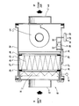
- An air purification system 10 comprises a contaminated side 16 and a clean side 18. The two sides are separated by a high efficiency particulate arrest (HEPA) filter 20 which removes from the air solid particles such as asbestos dust.
- HEPA high efficiency particulate arrest
- the contaminated side 16 of the system comprises an inlet duct 12 and a first pre-filter 14 which separates-out from the incoming air the largest of the solid particles.
- the first pre-filter 14 may be followed by a second pre-filter (not shown) which is sufficiently efficient to remove from the air 95% of the particles having a diameter of 5 ⁇ n or greater.
- a second pre-filter not shown
- one or both of these filters may be omitted.
- the HEPA filter 20 removes from the air 99.997% of particles having a diameter of 0.3 ⁇ n or more.
- the filters 14 and 20 are contained in a duct 50 and a space 27 is defined between the HEPA filter 20 and a wall 24 of the duct 50. Space 27 is sealed from the contaminated side by a seal 26 and from the clean side by a seal 28.
- a pump 30 positioned at the clean side of the system is connected by a first branch 32 of a duct 34 with the space 27 between the HEPA filter 20 and the duct wall 24.
- the pump 30 is connected by a second branch 36 of the duct 34 to a chamber 38 situated behind a control panel 40 which controls the operation of the system.
- a pressure gauge 42 is connected to the space 27 between the filter 20 and wall 24.
- a fan 44 draws air from the clean side of the system and out into the atmosphere through an outlet duct 46.
- the contaminated side 16 of the system is maintained at a pressure slightly below atmospheric pressure and the clean side 18 of the system is maintained at an even lower pressure by the action of the fan 44 moving air out through the duct 46. This pressure difference assists the action of the HEPA filter 20.
- the contaminated air moves into system 10 through the inlet 12 and passes through the pre-filter 14.
- the contaminated air then passes through the HEPA filter 20 which removes the remainder of the harmful solid particles and out through the duct 46.
- the HEPA filter 20 has a seal 26 isolating the space 27 around it from the contaminated side and a further seal 28, isolating the space 27 from the clean side 18.
- the space between the seals 26, 28 acts as a safety region and contains static clean air which is maintained at a pressure slightly higher than that of either the contaminated side 16 and the clear side 18. This pressure may be slightly above atmospheric pressure.
- the pump 30 pumps clean air upto a predetermined pressure into the safety region 27 from the clean side of the system 18 through branch 32 of duct 34. If either of, or both of, the seals 26, 28 begin to leak, this will be detected by pressure gauge 42 and relayed to control panel 40 which will activate either a warning means and/or the pump 30 so as to maintain the pressure in the safety region 27.
- control 40 will be coupled to a deactivating means such that when the pressure gauge reading falls below a predetermined level the deactivating means will be activated and the system will be shut down.
- a control panel 40 is situated on the wall of the duct 50 on the clean side of the system.
- the whole system is situated in a contaminated external atmosphere and therefore it is important to prevent contaminated air from passing through gaps 48 in the control panel around the dials and instruments and into the clean side of the system 18.
- a chamber 38 which acts as a safety region and contains static clean air at a higher pressure than either the surrounding atmosphere or the clean side 18 of the system.
- the pressure behind the control panel is monitored by pressure gauge 42.
- the clean air in chamber 38 is pumped into same from the clean side 18 of the system through branch 36 of duct 34 and by the same pump 30 which is used to pump air into the safety region 27.
- the safety region 38 works in a similar way to the safety region 27 in that the pressure difference between the safety region 28 and the surrounding atmosphere, ensures that any leakage will occur outwardly from the safety region 38 into the atmosphere rather than the other way about. Contaminated air is therefore prevented from entering the clean side of the system.
- an additional pressure gauge (not shown) is provided.
- an additional pump (not shown) is also provided to pump clean air from side 18 into chamber 38.
- the pressure gauge coupled to the control panel will detect a fall in pressure and below a predetermined level the the pressure gauge will be arranged to activate a deactivating means which will shut down the system.
- the system of the invention therefore provides a relatively simple way of preventing the escape of contaminated air from the contaminated side of an air purification system to the clean side.
- the system is especially used for when asbestos or other hazardous material must be removed from large areas making it impossible to locate the filtration system outside the contaminated area.
Landscapes
- Chemical & Material Sciences (AREA)
- Chemical Kinetics & Catalysis (AREA)
- Filtering Of Dispersed Particles In Gases (AREA)
Applications Claiming Priority (2)
| Application Number | Priority Date | Filing Date | Title |
|---|---|---|---|
| GB909004835A GB9004835D0 (en) | 1990-03-03 | 1990-03-03 | Improvement relating to air purification systems |
| GB9004835 | 1990-03-03 |
Publications (1)
| Publication Number | Publication Date |
|---|---|
| EP0445996A1 true EP0445996A1 (fr) | 1991-09-11 |
Family
ID=10671985
Family Applications (1)
| Application Number | Title | Priority Date | Filing Date |
|---|---|---|---|
| EP91301754A Withdrawn EP0445996A1 (fr) | 1990-03-03 | 1991-03-04 | Perfectionnements concernant des systèmes pour la purification de l'air |
Country Status (2)
| Country | Link |
|---|---|
| EP (1) | EP0445996A1 (fr) |
| GB (1) | GB9004835D0 (fr) |
Cited By (1)
| Publication number | Priority date | Publication date | Assignee | Title |
|---|---|---|---|---|
| CN107152728A (zh) * | 2017-05-19 | 2017-09-12 | 成都飞凯瑞科技有限公司 | 一种空气净化设备 |
Citations (6)
| Publication number | Priority date | Publication date | Assignee | Title |
|---|---|---|---|---|
| CH463250A (fr) * | 1966-09-19 | 1968-09-30 | Technicair Sa | Installation de ventilation comportant un filtre amovible placé dans une gaine |
| US3880625A (en) * | 1973-09-28 | 1975-04-29 | Moore And Hanks Company | Filter system |
| BE829117R (fr) * | 1975-05-15 | 1975-09-01 | Dispositif d'etancheite pour filtres a air a tres haute efficacite | |
| DE3126089A1 (de) * | 1981-07-02 | 1983-01-20 | Rainer 5820 Gevelsberg Schulz | Schwebstoffilter |
| EP0099212A2 (fr) * | 1982-07-07 | 1984-01-25 | United Kingdom Atomic Energy Authority | Ensemble filtrant |
| EP0242046A1 (fr) * | 1986-03-14 | 1987-10-21 | THORNE, John | Filtres à air |
-
1990
- 1990-03-03 GB GB909004835A patent/GB9004835D0/en active Pending
-
1991
- 1991-03-04 EP EP91301754A patent/EP0445996A1/fr not_active Withdrawn
Patent Citations (6)
| Publication number | Priority date | Publication date | Assignee | Title |
|---|---|---|---|---|
| CH463250A (fr) * | 1966-09-19 | 1968-09-30 | Technicair Sa | Installation de ventilation comportant un filtre amovible placé dans une gaine |
| US3880625A (en) * | 1973-09-28 | 1975-04-29 | Moore And Hanks Company | Filter system |
| BE829117R (fr) * | 1975-05-15 | 1975-09-01 | Dispositif d'etancheite pour filtres a air a tres haute efficacite | |
| DE3126089A1 (de) * | 1981-07-02 | 1983-01-20 | Rainer 5820 Gevelsberg Schulz | Schwebstoffilter |
| EP0099212A2 (fr) * | 1982-07-07 | 1984-01-25 | United Kingdom Atomic Energy Authority | Ensemble filtrant |
| EP0242046A1 (fr) * | 1986-03-14 | 1987-10-21 | THORNE, John | Filtres à air |
Cited By (1)
| Publication number | Priority date | Publication date | Assignee | Title |
|---|---|---|---|---|
| CN107152728A (zh) * | 2017-05-19 | 2017-09-12 | 成都飞凯瑞科技有限公司 | 一种空气净化设备 |
Also Published As
| Publication number | Publication date |
|---|---|
| GB9004835D0 (en) | 1990-04-25 |
Similar Documents
| Publication | Publication Date | Title |
|---|---|---|
| US6661346B1 (en) | Gas, fire and earthquake detector | |
| US4604111A (en) | Particulate contamination control method and filtration device | |
| US5067394A (en) | Airborne particle exhaust system | |
| JP6378551B2 (ja) | 非常時用空調システム | |
| US20080287050A1 (en) | Integrated Explosion Protection Apparatus For Supervision And Control Of Advanced Electrical Apparatuses | |
| US4905578A (en) | Apparatus for ventilating controlled areas | |
| KR100241139B1 (ko) | 에어 나이프를 이용한 이동식 분진비산억제장치 및 방법 | |
| US7294181B1 (en) | Air filtration and positive pressurization system for vehicles in environmentally adverse conditions | |
| US6146267A (en) | Device for separating two zones with different environment | |
| KR20150041838A (ko) | 에어로더 | |
| EP1369594B1 (fr) | Système d'étanchéité pour compresseur centrifugal | |
| US7618483B2 (en) | Housing assembly with bag presence indicator | |
| JPH11316298A (ja) | 放射性物質内包機器の処理方法および処理装置 | |
| Constance | Understanding industrial exhaust systems | |
| KR102841770B1 (ko) | 현장 방사선 모니터링이 가능한 분리 모듈형 이동식 공기 정화 장치 | |
| CN214664466U (zh) | 一种危废处理设备用风幕隔离装置 | |
| EP2865424A1 (fr) | Système de compresseur d'air | |
| CA2308938A1 (fr) | Robinet d'arret et detecteur d'ecoulement excessif de gaz, de tremblement de terre, de gaz et de fumee | |
| WO2024185114A1 (fr) | Armoire de sécurité et système d'échappement | |
| KR20190015839A (ko) | 공기안전대피소 | |
| Guidance | An Aid To The Design Of Ventilation For Glove Boxes Issue 01 | |
| JP3018748B2 (ja) | バッグフィルタの制御装置 | |
| Vollmer et al. | Safety concept for the tritium laboratory Karlsruhe (TLK) | |
| WO2024185112A1 (fr) | Armoire de sécurité et système de surveillance d'installation | |
| USH2221H1 (en) | Air supply system particularly suited to remove contaminants created by chemical, biological or radiological conditions |
Legal Events
| Date | Code | Title | Description |
|---|---|---|---|
| PUAI | Public reference made under article 153(3) epc to a published international application that has entered the european phase |
Free format text: ORIGINAL CODE: 0009012 |
|
| AK | Designated contracting states |
Kind code of ref document: A1 Designated state(s): AT BE CH DE DK ES FR GB GR IT LI LU NL SE |
|
| 17P | Request for examination filed |
Effective date: 19920307 |
|
| STAA | Information on the status of an ep patent application or granted ep patent |
Free format text: STATUS: THE APPLICATION IS DEEMED TO BE WITHDRAWN |
|
| 18D | Application deemed to be withdrawn |
Effective date: 19931001 |