EP0446028A2 - Verfahren und Vorrichtung zur Verbesserung des Rauschabstandes bei der Bilderzeugung von einem, in einem halb-durchsichtigen Medium, verborgenen Körper - Google Patents
Verfahren und Vorrichtung zur Verbesserung des Rauschabstandes bei der Bilderzeugung von einem, in einem halb-durchsichtigen Medium, verborgenen Körper Download PDFInfo
- Publication number
- EP0446028A2 EP0446028A2 EP91301848A EP91301848A EP0446028A2 EP 0446028 A2 EP0446028 A2 EP 0446028A2 EP 91301848 A EP91301848 A EP 91301848A EP 91301848 A EP91301848 A EP 91301848A EP 0446028 A2 EP0446028 A2 EP 0446028A2
- Authority
- EP
- European Patent Office
- Prior art keywords
- random
- medium
- imaging
- light
- signal
- Prior art date
- Legal status (The legal status is an assumption and is not a legal conclusion. Google has not performed a legal analysis and makes no representation as to the accuracy of the status listed.)
- Withdrawn
Links
Images






Classifications
-
- G—PHYSICS
- G01—MEASURING; TESTING
- G01N—INVESTIGATING OR ANALYSING MATERIALS BY DETERMINING THEIR CHEMICAL OR PHYSICAL PROPERTIES
- G01N21/00—Investigating or analysing materials by the use of optical means, i.e. using sub-millimetre waves, infrared, visible or ultraviolet light
- G01N21/17—Systems in which incident light is modified in accordance with the properties of the material investigated
- G01N21/47—Scattering, i.e. diffuse reflection
- G01N21/4795—Scattering, i.e. diffuse reflection spatially resolved investigating of object in scattering medium
-
- G—PHYSICS
- G01—MEASURING; TESTING
- G01N—INVESTIGATING OR ANALYSING MATERIALS BY DETERMINING THEIR CHEMICAL OR PHYSICAL PROPERTIES
- G01N21/00—Investigating or analysing materials by the use of optical means, i.e. using sub-millimetre waves, infrared, visible or ultraviolet light
- G01N21/17—Systems in which incident light is modified in accordance with the properties of the material investigated
- G01N2021/1765—Method using an image detector and processing of image signal
- G01N2021/177—Detector of the video camera type
-
- G—PHYSICS
- G01—MEASURING; TESTING
- G01N—INVESTIGATING OR ANALYSING MATERIALS BY DETERMINING THEIR CHEMICAL OR PHYSICAL PROPERTIES
- G01N21/00—Investigating or analysing materials by the use of optical means, i.e. using sub-millimetre waves, infrared, visible or ultraviolet light
- G01N21/17—Systems in which incident light is modified in accordance with the properties of the material investigated
- G01N2021/178—Methods for obtaining spatial resolution of the property being measured
-
- G—PHYSICS
- G01—MEASURING; TESTING
- G01N—INVESTIGATING OR ANALYSING MATERIALS BY DETERMINING THEIR CHEMICAL OR PHYSICAL PROPERTIES
- G01N21/00—Investigating or analysing materials by the use of optical means, i.e. using sub-millimetre waves, infrared, visible or ultraviolet light
- G01N21/17—Systems in which incident light is modified in accordance with the properties of the material investigated
- G01N2021/1789—Time resolved
- G01N2021/1791—Time resolved stroboscopic; pulse gated; time range gated
-
- G—PHYSICS
- G01—MEASURING; TESTING
- G01N—INVESTIGATING OR ANALYSING MATERIALS BY DETERMINING THEIR CHEMICAL OR PHYSICAL PROPERTIES
- G01N2201/00—Features of devices classified in G01N21/00
- G01N2201/06—Illumination; Optics
- G01N2201/069—Supply of sources
- G01N2201/0696—Pulsed
- G01N2201/0697—Pulsed lasers
Definitions
- the present invention relates generally to imaging objects and more particularly to a method and apparatus for improving the signal to noise ratio of an image formed of an object hidden in or behind a semi-opaque random media, the object being either opaque, transparent or semi-transparent.
- the quality of an image formed of an object is improved by using space gate imaging or time gate imaging or space time gate imaging.
- space gate imaging a small segment of the object is illuminated at a time. The scattered light is passed through a spatial noise filter.
- an aperture is open at the position of the image segment which corresponds to the segment of the illuminated object. A full image is obtained by scanning the object segment by segmemt and simultaneously recording the signal at the corresponding image segment.
- time gate imaging the unscattered (i.e.
- ballistic portion of the pulse which contains the information of the object is temporally separated from the other (i.e scattered) portions which contain the noise using a ultrafast laser pulse and temporal gating device.
- time gating is based on the principle that the unscattered (ballistic) portion of the light pulse travels straight through the medium, and arrives at an earlier time than those portions that are scattered away from the straight line and as a result travel through longer distances.
- a combination of space and time gate imaging, called space time gate imaging eliminates most of the scattered light, producing as a result an image with a much higher signal to noise ratio.
- further improvements can be achieved by increasing the time separation between the ballistic and scattered light.
- One way of achieving this is by increasing the thickness random medium.
- Another way of achieving this is by introducing small scatterers into the random medium. Still another way of achieving this is by introducing an absorbing dye into the medium. A further way of achieving this is by using a wavelength for the light which is in the absorption spectrum of the random medium.
- the signal to noise ratio can also be improved by making the random medium either more random so as to increase the time separation between the scattered and unscattered and or by making the random medium more ordered so that less scattering will occur.
- the sources of multiple scattered light noise in forming an image of an object 10 are classified and illustrated by rays in Fig. 1.
- the light from object 10 on passing through a random medium 11 may be divided into two portions, ray (1) and ray (1′).
- Ray (1′) includes all incident rays except ray (1).
- a spatial filter 12 which consists of a pair of lenses 13 and 15 and an aperture 17 placed at the focal point is used. This is shown in Fig. 2 where the light scattered away from the forward direction are removed and the image formed is recorded by a recording system 19.
- sources of noise which are rays (1′f) and (1b) at position x1.
- Figs. 3 and 4 an arrangement referrred to as space gate imaging for removing the noise from rays (1′) and (1d).
- the noise constribution from rays (1′) is removed by blocking ray (1′) itself so that it is not incident on the random medium. This elimination can be achieved either by placing an aperture 21 which allows only ray (1) through or just illuminates the medium by only ray (1).
- Multiple scattered light other than the forward direction of ray (1) is removed by the collimating lenses 13 and 15 and aperture 17 at the focal point.
- the noise of ray (1d) is removed either by placing an aperture 23 in front of the recording system as shown in Fig. 3 or by placing an aperture 25 in front of the collimating lenses 13 and 15 and aperture 17 as shown in Fig. 4. This reduction of unwanted multiple scattered light and some incident rays improves the quality of the image significantly. Nevertheless, the weakest noise represented by ray (1b) remains.
- the fundamental principle of the space gate imaging is illuminating a small segment of the object, filtered out the multiple scattered light which scattered away from the forward direction, and the signal fall on the corresponding image position is recorded.
- the image is constructed after scanning the whole object segment by segment.
- ray (1b) In the space gate imaging system described above, the noise represented by ray (1b) cannot be removed. This noise can be significant in a strongly scattering medium. To illustrate this, the relative intensity between ray (1a) and (1b) are time resolved.
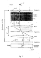
- the experiment setup is shown in apparatus 31 in Fig. 5 and the measured results are presented by two pictures in Figs. 6(a) and 6(b).
- a beam of pulses from a colliding pulse mode locked laser 33 is split into three parts by a pair of beamsplitters 35 and 37.
- One part 39 is deflected off a pair of mirrors 41 and 43 and then passed through an aperture 45 and a sample 47 and then imaged by a lens 49 through a beamsplitter 50 into the input end of a streak camera 51.
- the streak image formed at the output end is converted into an electrical signal by a silicon intensified target (SIT) detector 53 and then fed into a computer 57.
- SIT silicon intensified target
- Another part 59 of the beam from laser 33 is deflected off a pair of mirrors 61 and 63 and used as a reference pulse for streak camera 51.
- the third part 65 of the pulse from laser 33 strikes a photodiode 67 and generates a trigger signal which is used to trigger the deflection circuits (not shown) in streak camera 51.
- the degree of whiteness in the two pictures measure the intensity of the light falling on the picture.
- the horizontal and vertical axis are angle and time axis, respectively.
- a small white spot corresponds to the signal from ray (1a).
- the broad white distribution correspond to the scattered signals which has large time and angular distributions.
- the first peak is the reference pulse
- the second peak is the ballistic pulse ( ray (1a)
- the broad distribution in angle and time corresponds to the scattered pulse ( ray (1b)).
- the time integrated intensity of ray (1b) can be greater than the ballistic portion (1a). This large noise from ray (1b) will overshadow the image in space gating imaging. Time gating can select ray (1a) more and enhances the image quality.
- Space-time gate imaging is similar to space gate imaging (Figs. 3 and 4) except that the recording system of the space-time gate imaging temporally gates the signal component of the scattered light.
- the leading edge of the light pulse which consists of mainly the signal (1a) is measured. This will substantially improved the quality of the image.
- a complete imaging system requires several additional steps to be taken in succession.
- This signal is stored in the memory in a computer.
- the whole object is scanned segment by segment and the signal at the corresponding segment on the image plane is recorded and stored. This scanning can be done by moving the object alone, or optical deflection by acoustic modulation, or by synchronizing the motion of illumination spot and detecting spot.
- the image is then reconstructed from all the stored signals and the picture is shown on the video screen.
- the picture can further be used for analysis and diagnosis such as by comparing the images in the memory of the computer.
- FIG. 7 A block diagram shown in Fig. 7 illustrates one of the typical imaging systems taught by our invention.
- a cw or ultrafast laser pulse is generated from a laser light source 71 and incident on the medium 73 in which an object 10 is hidden.
- the multiple scattered light strikes a space gate noise filter 75 of the type described in Figs. 3 and 4.
- An optical fiber 77 is used to collect the unscattered (ballistic) and scattered light.
- the collection fiber 77 is placed at the image point which corresponds to the illuminated point on the object, and the signal is collected and guided to a detector 79.
- Light source 71 and fiber 77 are synchronized in positions of illumination and collection by a controller 81 which is is monitored by computer in a computerized recording system 83 so that the correlation between the position of illumination on the object 10 and the signal collected is established.
- An acoustic optical deflection modulator (not shown) can also be used to deflect the beams to different locations on objects. Also, a selected portion can be collected and deflected by another acoustic optical deflector. This is similar to a bar code reader.
- the scanning can also be done by translating the position of object 10 alone. Three dimensional information of object 10 can be obtained by an additional degree of scanning such as rotating the object.
- the signal collected by the optical fiber 77 is sent into a detector system where the intensity is measured and stored into computer in system 83.
- Detector 79 may comprise, for example, a photomultiplier tub or a streak camera coupled to an SIT or video camera or a Kerr cell coupled to an SIT or a video camera.
- detector 79 is a photomultiplier tube of the equivalent, then the system is a space gate type of system. On the other hand, if the detector system is a streak camera combination or a Kerr cell combination or similar combination, then the system is a space gate, time gate type of system.
- the output of detector system 79 is fed into a computer 81 for processing and recording.
- Computer 81 and light source 71 are controlled by controller 83 which receives instructions from computer 81. A complete image can be reconstructed after a full scan or many full scans.
- FIG. 8 Another versatile space-time imaging system 91 which incorporates a streak camera is shown in Fig. 8.
- the system includes two slits (or apertures) 93 and 95, a lens 97, and a translation stage 99.
- Slits 93 and 95 and an imaging lens 97 comprise a space gating device where all the light scattered away from the straight line propagation is cut off by the input slit or the aperture 101 of a streak camera 103.
- the object 10 inside random medium 105 is illuminated by ultrafast laser pulses.
- the scattered light is temporally dispersed by streak camera 103.
- the output streak image is converted into an electrical signal by SIT 107 and fed into a computer 109.
- Stage 99 is controlled by controller 111 which is controlled by computer 109.
- the resolution of the image formed by the ballistic component of the pulse is governed by wave diffraction, i.e. the size of the apertures of illumination and collection and the wavelength of light. This resolution is the same as the resolution of usual imaging of an object without multiple light scattering. Using visible radiation, the resolution is in the order of micrometers. This resolution will make imaging of small particle possible.
- the diffusive component of the pulse may temporally overlap with the ballistic component within the time resolution of the detecting system. This overlapping increases the noise and reduces the resolution of the image. If the intensity of the diffusive component in the overlapping region is comparable to or larger than the ballistic component, the object may be deemed unobservable.
- the temporal separation between the diffusive component and the ballistic component can be increased by increasing the thickness of the media, increasing the number density of the scatterers, and decreasing the size of the scatterers or introducing particles smaller than the wavelength of the light into the random medium.
- the quality can be improved by making the medium more random or less random (i.e. ordered). In these cases although the intensity of the ballistic pulse decreases the relative intensity of the ballistic to diffusive pulse within the time resolution increases. This increase in relative intensity enhances the quality of the image.
- the diffusive portion may temporally overlap with the ballistic portion of the pulse within the temporal resolution of the detecting system. This overlapping decreases the resolution of the image. To improve the image resolution to a microns scale one has to resolve the ballistic component from the diffusive component. This can be achieved by any of the ways as stated above:
- the enhancement of image quality by increasing the medium thickness can be understood by looking at how the intensity for ballistic and diffusive components decrease with distance z from the source.
- the intensity of the ballistic pulse is given by: where L t is the transport means free path.
- D v L t /3 is the diffusion coefficient
- v the velocity of the light in the medium.
- the change of ratio of ballistic to diffusive intensity (I b /I d ) at various distances from the light source are illustrated by two examples.
- the diffusive intensity is the total time integrated intensity measured at the initial portion of the scattered pulse within the time resolution of the detector.
- the diffusive intensity may be presented by the value computed at time in the middle of the time resolution.
- the diffusive intensity increases faster than the ballistic intensity as z increase.
- z/ (4vt/3) should be greater than one.
- t 5ps
- v the light velocity in water
- z c 1500 ⁇ m .
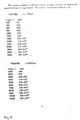
- This critical value is in agreement with the computed data in table 9(a) .
- z ⁇ 500 ⁇ m the ratio is less than 1; for z > 1500 ⁇ m, the ratio increase rapidly with z.
- the ratio increase rapidly with distance z.
- Figs. 6(a) and 6(b) show the angular and temporal information of the pulse after propagating through a 10 mm slab of random media.
- the random media consist of latex beads suspended in water.
- the ballistic pulse is clearly separated from the diffusive pulse in fig 6 (a).
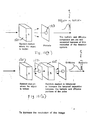
- Fig. 10(a) shows the effect of light passing through a random medium 121 and a pinhole 123.
- Fig. 10(b) shows the effect of introducing a slab 125 of uniform random medium of small particles into the path of scattered light from an object hidden (not shown) in a slab 127 to be image in order to increase (1) the temporal separation between the ballistic and diffusive pulse, and (2) the ratio of ballistic to diffusive intensity.
- This additional random medium delays the diffusive portion of the pulse with respect to the ballistic portion so that they can be further temporally separated within the resolution of the detecting system.
- the thickness of the slab should be greater than z c .
- the slab should consist of scatterers much smaller than the wavelength of the light. The small scatterers scatter the light in all directions so as to increase the temporal separation between the diffusive and the ballistic pulse.
- This method will increase the temporal distance between the ballistic and diffusive parts so as to improve imaging capability. If the object is hidden inside a fluid type of medium, then the randomness of the media can be increased by introducing some small scatterer into the medium itself. This method also increase the temporal separation between the ballistic and diffusive pulse after propagating through the medium and improve the quality of the image if the selection of ballistic part is made.
- a spatial filter will remove light which is scattered away from the collinear direction of the signal.
- a highly scattering medium there is a substantial portion of multiple scattered light which, after passing through a random medium, travels in the same direction as the ballistic signal. This multiply scattered light exiting from the random medium in the same direction as the ballistic signal cannot be eliminated with a spatial filter.
- the introduction of an absorbing dye into a random medium can substantially reduce the noise arising from multiple scattered light with respect to the ballistic signal.
- the signal to noise ratio can be substantially increased by orders of a magnitude using this absorption approach.
- Absorption can also be used to improve the capability of seeing through a random medium, including biological and medical medium by selecting a wavelength for the light which is stongly absorbed by the random medium.
- the principle behind the absorption imaging approach is based on the fact that multiply scattered light undergoes random walk in the medium and thus travels over a longer path length than that of the ballistic signal.
- the distance the ballistic signal transverses through the slab of random medium is equal to the thickness of the slab. Light traveling over a longer path length has a higher probability of being attenuated.
- the introduction of a dye into a random medium will preferentially absorb the mulitple scattered light component over the ballistic portion.
- the temporal profile of the scattered pulse exiting at a point on the opposite side of the slab predicted by the diffusion theory is is the speed of photon.
- z is the thickness of the slab
- L t is the transport mean free path
- L a is the absorption length.
- the total intensity of the diffuse light is obtained by integrating eq. (1) with respect to time from 0 to ⁇ . The amount is given by Since the transmitted light is scattered in all directions, the intensity of the light scattered within a fraction of solid angle is given by On the other hand, the intensity of the ballistic signal transversing over distance z is reduced by where L S is the photon scattering mean free path.
- Fig. 11 shows the schematic of an experimental setup used to test the absorbtion feature of the invention.
- Ultrafast laser pulses of 80 fs were generated at a repetition rate of 82 MHz from a colliding Pulse mode-locked dye laser system 141.
- the laser power was 5 mW and the laser wavelength was centered at 620 nm.
- the beam was split into three parts 143, 145 and 147 by a pair of beamsplitters 149 and 151. Part 147 was deflected off a mirror 153 and expanded from 4 mm to 35 mm beam diameter by an expander 155.
- the center portion of the expanded laser beam was deflected by a mirror 156 and incident through an aperture 156-1 on a random medium in a cylindrical glass cell 157 of 50 mm in diameter and 10 mm thick through an aperture 159.
- the random medium consisted of latex beads 10% concentration suspended in water and of 0.091 um diameter. Photons scattered out of the cell were lost.
- a black pinhole 161 of 2 mm diameter was placed at the center on the opposite side of cell 157.
- the temporal distribution of the photon exit from this pin hole in the forward direction within 4 mrad was measured by a synchroscan streak camera163.
- a lens 165 imaged pin hole 161 onto the input slit of streak camera 163.
- the diameter of the incident beam was set to 20 mm (any further increase in the beam diameter will not change the pulse profile of the scattered photons.)
- the measured scattered pulse profile can be described by equation (1) when the thickness of the random medium is greater than 10 transport mean free path.
- Beam part 145 was deflected off a pair of mirrors 144-1 and 145-2 off a beamsplitter 145-3 and used as a reference pulse. Beam part 143 was fed into a photodiode 167 which generated a trigger signal for streak camera 163.
- the output of streak camera 163 is converted to electrical signals by SIT 167 which are fed into computer 169 for processing.
- the resulting image is displayed on video monitor 171.
- the time resolved profiles of signal and diffuse light for different amounts of absorbing dye added into the random medium are presented in Fig. 12.
- the small peak at time 0 PSEC is the ballistic signal.
- This ballistic signal light arises from coherent interference amount the multiple scattered light traveling in the forward direction.
- the ballistic signal component is followed in time by a large temporal distribution of multiply scattered light.
- the total intensity of the diffuse light component is 130 times more than the intensity of the ballistic signal. It is not possible to see through such a cloudy medium.
- Figs. 2(b), (c) and (d) demonstrate several salient features.
- the transmitted pulse profiles change by increasing amount of absorbing dye in the random medium.
- the diffuse scattered light at later times which travel over a longer distances are attenuated more.
- the diffuse light intensity decreases more rapidly as more dye is added.
- the absorption lengths from these media were obtained experimentally by preparing the dye solutions (no beads in it).
- the transmission of the dye solutions mere measured by a spectrophotometer.
- the percentage transmnission of these dye solutions corresponding to curves (a), (b), (c), and (d) of Fig. 12 are 100, 92.5, 80.6 and 62.4% respectively.
- Fig. 12(d) shows that the diffuse light intensity is substantially reduced with respect to signal intensity as compared with Fig. 12(a). In the case of Fig. 12(d) the total intensity of the diffuse light is equal to the intensity of the ballistic signal. The ballistic portion is enhanced over the diffuse portion.
- the total intensity of the diffuse light compared with the intensity of the signal light.
- the total intensity of the diffuse light (noise) and signal are plotted in Fig. 14. As the absorption length decreases (increase in absorption), the intensity of the diffuse light decreases much faster than that of the signal light.
- the absorption lengths are varied from 1000 to 5 mm. In these limits, the diffuse intensity decreases from 7 x 10 ⁇ 6 to 5 x 10 ⁇ 21; an intensity drop by a factor of 1015.
- the corresponding intensity drops of the ballistic component decreases from 1 x 10 ⁇ 8 to 1 x 10 ⁇ 9, a drop of only by a factor of 10.
- the diffuse noise can be substantially reduced with respect to ballistic signal through absorption in a random medium.
- This absorption which reduces the noise with respect to signal is important to improve the quality of the image of an object hidden in a random or biomedical medium.
- the medium is made more random, the time separation between the ballistic and diffused light will be increased and as a result improve the signal to noise ratio in a time gating system. Furthermore, if the medium is made more ordered (i.e. less random) there will be less scattered light and hence a higher signal to noise ratio.
- the illuminating radiation used in this invention is not limited to visible light, but rather can also be other forms of electromagnetic radiation such as radio waves, infrared radiation, ultraviolet radiation, x-rays and gamma rays.
Landscapes
- Physics & Mathematics (AREA)
- Optics & Photonics (AREA)
- Health & Medical Sciences (AREA)
- Life Sciences & Earth Sciences (AREA)
- Chemical & Material Sciences (AREA)
- Analytical Chemistry (AREA)
- Biochemistry (AREA)
- General Health & Medical Sciences (AREA)
- General Physics & Mathematics (AREA)
- Immunology (AREA)
- Pathology (AREA)
- Investigating Or Analysing Materials By Optical Means (AREA)
- Image Processing (AREA)
- Image Analysis (AREA)
Applications Claiming Priority (2)
| Application Number | Priority Date | Filing Date | Title |
|---|---|---|---|
| US07/489,942 US5140463A (en) | 1990-03-08 | 1990-03-08 | Method and apparatus for improving the signal to noise ratio of an image formed of an object hidden in or behind a semi-opaque random media |
| US489942 | 1990-03-08 |
Publications (2)
| Publication Number | Publication Date |
|---|---|
| EP0446028A2 true EP0446028A2 (de) | 1991-09-11 |
| EP0446028A3 EP0446028A3 (en) | 1992-08-05 |
Family
ID=23945924
Family Applications (1)
| Application Number | Title | Priority Date | Filing Date |
|---|---|---|---|
| EP19910301848 Withdrawn EP0446028A3 (en) | 1990-03-08 | 1991-03-06 | Method and apparatus for improving the signal to noise ratio of an image formed of an object hidden or behind a semi-opaque random media |
Country Status (3)
| Country | Link |
|---|---|
| US (1) | US5140463A (de) |
| EP (1) | EP0446028A3 (de) |
| JP (1) | JP2520197B2 (de) |
Cited By (6)
| Publication number | Priority date | Publication date | Assignee | Title |
|---|---|---|---|---|
| WO1996023524A1 (en) * | 1995-02-02 | 1996-08-08 | Nycomed Imaging A/S | Contrast media for in vivo imaging based on light transmission on reflection |
| WO1997019632A1 (en) * | 1995-11-28 | 1997-06-05 | Aerospace Research Technologies Inc. | Method and apparatus for detecting malignancies in living tissue |
| US6159445A (en) * | 1994-07-20 | 2000-12-12 | Nycomed Imaging As | Light imaging contrast agents |
| WO2001019143A1 (en) * | 1999-09-09 | 2001-03-15 | The Government Of The United States Of America, As Represented By The Secretary, Department Of Health & Human Services, The National Institutes Of Health | Time-gated imaging with a split-beam source |
| US6540981B2 (en) | 1997-12-04 | 2003-04-01 | Amersham Health As | Light imaging contrast agents |
| EP1371323A1 (de) * | 1995-12-27 | 2003-12-17 | Sysmex Corporation | Nichtinvasive Vorrichtung zur Blutuntersuchung |
Families Citing this family (48)
| Publication number | Priority date | Publication date | Assignee | Title |
|---|---|---|---|---|
| US5257085A (en) * | 1991-04-24 | 1993-10-26 | Kaman Aerospace Corporation | Spectrally dispersive imaging lidar system |
| US5467122A (en) * | 1991-10-21 | 1995-11-14 | Arete Associates | Underwater imaging in real time, using substantially direct depth-to-display-height lidar streak mapping |
| US5644429A (en) * | 1992-07-23 | 1997-07-01 | Research Foundation Of City College Of New York | 2-dimensional imaging of translucent objects in turbid media |
| US5371368A (en) * | 1992-07-23 | 1994-12-06 | Alfano; Robert R. | Ultrafast optical imaging of objects in a scattering medium |
| US5949077A (en) * | 1992-08-10 | 1999-09-07 | Alfano; Robert R. | Technique for imaging an object in or behind a scattering medium |
| US5506616A (en) * | 1992-10-07 | 1996-04-09 | The United States Of America As Represented By The Secretary Of The Navy | Differential imaging for sensitive pattern recognition |
| US5303710A (en) * | 1992-11-03 | 1994-04-19 | The United States Of America As Represented By The Secretary Of The Navy | Apparatus for imaging an object in or through a scattering medium using coherent anti-Stokes Raman scattering |
| US5270853A (en) * | 1992-11-30 | 1993-12-14 | The United States Of America As Represented By The Secretary Of The Navy | Method and apparatus for imaging an object in or through a scattering medium by using multiple-wave mixing |
| US6215587B1 (en) * | 1994-02-14 | 2001-04-10 | Robert R. Alfano | Microscope imaging inside highly scattering media |
| US5625458A (en) * | 1994-11-10 | 1997-04-29 | Research Foundation Of City College Of New York | Method and system for imaging objects in turbid media using diffusive fermat photons |
| US5919140A (en) * | 1995-02-21 | 1999-07-06 | Massachusetts Institute Of Technology | Optical imaging using time gated scattered light |
| US5710429A (en) * | 1995-04-06 | 1998-01-20 | Alfano; Robert R. | Ultrafast optical imaging of objects in or behind scattering media |
| EP0871862A4 (de) * | 1995-04-10 | 1999-10-27 | Bell Communications Res | Diffusionsbildgebung unter verwendung direkter rekonstruktion gestreuter strahlung |
| US5787888A (en) * | 1995-05-15 | 1998-08-04 | Schotland; John Carl | Absorption tomography system and method using direct reconstruction of scattered radiation |
| US5832922A (en) * | 1995-05-15 | 1998-11-10 | Schotland; John Carl | Diffusion Tomography system and method using direct reconstruction of scattered radiation |
| US5747810A (en) * | 1995-05-15 | 1998-05-05 | Univ. Of Pennsylvania | Simultaneous absorption and diffusion tomography system and method using direct reconstruction of scattered radiation |
| GB2303511A (en) * | 1995-07-19 | 1997-02-19 | Univ Manchester | Compensating for backscattered light |
| US5721761A (en) * | 1996-09-20 | 1998-02-24 | Ferlic; Daniel J. | Radiographic grid with reduced lamellae density artifacts |
| US5936739A (en) * | 1997-01-29 | 1999-08-10 | Sandia Corporation | Gated frequency-resolved optical imaging with an optical parametric amplifier |
| DE19725633C1 (de) * | 1997-06-17 | 1998-12-17 | Zentrum Fuer Neuroinformatik G | Verfahren und Anordnung zur Analyse der Beschaffenheit einer Oberfläche |
| US5956139A (en) * | 1997-08-04 | 1999-09-21 | Ohio Aerospace Institute | Cross-correlation method and apparatus for suppressing the effects of multiple scattering |
| US5936233A (en) * | 1998-02-26 | 1999-08-10 | The Curators Of The University Of Missouri | Buried object detection and neutralization system |
| US6348942B1 (en) | 1998-03-06 | 2002-02-19 | The United States Of America As Represented By The Secretary Of The Army | Enhanced underwater visibility |
| US6662042B1 (en) * | 2000-08-22 | 2003-12-09 | Richard J. Grable | Diagnostic tomographic laser imaging apparatus |
| WO2001020307A1 (en) * | 1999-09-14 | 2001-03-22 | The Research Foundation Of State University Of New York | Method and system for enhanced imaging of a scattering medium |
| US7224905B2 (en) | 2000-04-07 | 2007-05-29 | The Regents Of The University Of California | Remotely-interrogated high data rate free space laser communications link |
| US6633683B1 (en) * | 2000-06-26 | 2003-10-14 | Miranda Technologies Inc. | Apparatus and method for adaptively reducing noise in a noisy input image signal |
| US7106972B2 (en) * | 2001-04-04 | 2006-09-12 | The Research Foundation Of The City University Of New York | Methods of improving line of sight wireless optical communication through adverse environmental conditions |
| US6784988B2 (en) * | 2002-07-17 | 2004-08-31 | Hamilton Associates, Inc. | Apparatus and process for analyzing a stream of fluid |
| US7826878B2 (en) * | 2004-12-07 | 2010-11-02 | Research Foundation Of City University Of New York | Optical tomography using independent component analysis for detection and localization of targets in turbid media |
| EP3229010A3 (de) | 2007-10-25 | 2018-01-10 | Washington University in St. Louis | Konfokale fotoakustische mikroskopie mit optischer lateraler auflösung |
| US8416421B2 (en) * | 2008-10-01 | 2013-04-09 | Washington University | Optical coherence computed tomography |
| WO2010080991A2 (en) | 2009-01-09 | 2010-07-15 | Washington University In St. Louis | Miniaturized photoacoustic imaging apparatus including a rotatable reflector |
| CN102883658B (zh) * | 2009-11-19 | 2016-06-22 | 调节成像公司 | 用于使用结构化照明经由单元件检测来分析浑浊介质的方法和设备 |
| WO2011127428A2 (en) | 2010-04-09 | 2011-10-13 | Washington University | Quantification of optical absorption coefficients using acoustic spectra in photoacoustic tomography |
| US8997572B2 (en) | 2011-02-11 | 2015-04-07 | Washington University | Multi-focus optical-resolution photoacoustic microscopy with ultrasonic array detection |
| KR101382921B1 (ko) * | 2012-06-28 | 2014-04-08 | 엘지이노텍 주식회사 | 카메라, 그의 이미지 센서 및 동작 방법 |
| WO2014063005A1 (en) | 2012-10-18 | 2014-04-24 | Washington University | Transcranialphotoacoustic/thermoacoustic tomography brain imaging informed by adjunct image data |
| BR112015010459B1 (pt) | 2012-11-07 | 2021-01-26 | Modulated Imaging, Inc. | método para a medição de uma amostra turva |
| WO2015077355A1 (en) | 2013-11-19 | 2015-05-28 | Washington University | Systems and methods of grueneisen-relaxation photoacoustic microscopy and photoacoustic wavefront shaping |
| US11672426B2 (en) | 2017-05-10 | 2023-06-13 | California Institute Of Technology | Snapshot photoacoustic photography using an ergodic relay |
| WO2019116803A1 (ja) * | 2017-12-13 | 2019-06-20 | パナソニックIpマネジメント株式会社 | 光センシング装置 |
| EP3836831A4 (de) | 2018-08-14 | 2022-05-18 | California Institute of Technology | Multifokale photoakustische mikroskopie durch ein ergodisches relais |
| WO2020051246A1 (en) | 2018-09-04 | 2020-03-12 | California Institute Of Technology | Enhanced-resolution infrared photoacoustic microscopy and spectroscopy |
| US11369280B2 (en) | 2019-03-01 | 2022-06-28 | California Institute Of Technology | Velocity-matched ultrasonic tagging in photoacoustic flowgraphy |
| US11986269B2 (en) | 2019-11-05 | 2024-05-21 | California Institute Of Technology | Spatiotemporal antialiasing in photoacoustic computed tomography |
| US12504363B2 (en) | 2021-08-17 | 2025-12-23 | California Institute Of Technology | Three-dimensional contoured scanning photoacoustic imaging and virtual staining |
| US12593986B2 (en) | 2023-04-12 | 2026-04-07 | California Institute Of Technology | Transmission mode-photoacoustic tomography of the human brain through an acoustic window |
Family Cites Families (10)
| Publication number | Priority date | Publication date | Assignee | Title |
|---|---|---|---|---|
| US4203037A (en) * | 1977-08-01 | 1980-05-13 | University Of Pittsburgh | Collimated radiation apparatus |
| US4515165A (en) | 1980-02-04 | 1985-05-07 | Energy Conversion Devices, Inc. | Apparatus and method for detecting tumors |
| JPS56146155A (en) * | 1980-04-15 | 1981-11-13 | Mita Ind Co Ltd | Electrostatic copying machine |
| US4493096A (en) * | 1982-12-17 | 1985-01-08 | General Electric Company | Method of X-ray imaging using slit scanning with controlled target erase |
| US4807637A (en) | 1984-08-20 | 1989-02-28 | American Science And Engineering, Inc. | Diaphanography method and apparatus |
| US4707128A (en) * | 1984-12-31 | 1987-11-17 | Subsea Engineering Associates, Inc. | Turbid media viewing system |
| US4710637A (en) * | 1986-02-10 | 1987-12-01 | Eastman Kodak Company | High efficiency fluorescent screen pair for use in low energy X radiation imaging |
| JPS62277538A (ja) * | 1986-05-27 | 1987-12-02 | Hamamatsu Photonics Kk | 3次元物体計測装置 |
| JPS6326555A (ja) * | 1986-07-18 | 1988-02-04 | Hamamatsu Photonics Kk | 光を用いた物体内部構造の3次元計測装置 |
| US4875227A (en) * | 1986-12-06 | 1989-10-17 | Rossi Remo J | Anti-scatter grid system |
-
1990
- 1990-03-08 US US07/489,942 patent/US5140463A/en not_active Expired - Fee Related
-
1991
- 1991-01-31 JP JP3010971A patent/JP2520197B2/ja not_active Expired - Lifetime
- 1991-03-06 EP EP19910301848 patent/EP0446028A3/en not_active Withdrawn
Cited By (7)
| Publication number | Priority date | Publication date | Assignee | Title |
|---|---|---|---|---|
| US6159445A (en) * | 1994-07-20 | 2000-12-12 | Nycomed Imaging As | Light imaging contrast agents |
| WO1996023524A1 (en) * | 1995-02-02 | 1996-08-08 | Nycomed Imaging A/S | Contrast media for in vivo imaging based on light transmission on reflection |
| US7014839B2 (en) | 1995-02-02 | 2006-03-21 | Amersham Health As | Light imaging contrast agents |
| WO1997019632A1 (en) * | 1995-11-28 | 1997-06-05 | Aerospace Research Technologies Inc. | Method and apparatus for detecting malignancies in living tissue |
| EP1371323A1 (de) * | 1995-12-27 | 2003-12-17 | Sysmex Corporation | Nichtinvasive Vorrichtung zur Blutuntersuchung |
| US6540981B2 (en) | 1997-12-04 | 2003-04-01 | Amersham Health As | Light imaging contrast agents |
| WO2001019143A1 (en) * | 1999-09-09 | 2001-03-15 | The Government Of The United States Of America, As Represented By The Secretary, Department Of Health & Human Services, The National Institutes Of Health | Time-gated imaging with a split-beam source |
Also Published As
| Publication number | Publication date |
|---|---|
| JPH0556982A (ja) | 1993-03-09 |
| US5140463A (en) | 1992-08-18 |
| EP0446028A3 (en) | 1992-08-05 |
| JP2520197B2 (ja) | 1996-07-31 |
Similar Documents
| Publication | Publication Date | Title |
|---|---|---|
| US5140463A (en) | Method and apparatus for improving the signal to noise ratio of an image formed of an object hidden in or behind a semi-opaque random media | |
| US5710429A (en) | Ultrafast optical imaging of objects in or behind scattering media | |
| US5451785A (en) | Upconverting and time-gated two-dimensional infrared transillumination imaging | |
| US4649275A (en) | High resolution breast imaging device utilizing non-ionizing radiation of narrow spectral bandwidth | |
| JP3187129B2 (ja) | 粒子分析装置 | |
| US4807637A (en) | Diaphanography method and apparatus | |
| US5644388A (en) | Imaging flow cytometer nearly simultaneously capturing a plurality of images | |
| DE3875069T2 (de) | Vorrichtung zur bestimmung der asymmetrie von teilchen. | |
| US5247339A (en) | Flow imaging cytometer | |
| US4407008A (en) | Method and apparatus for light-induced scanning-microscope display of specimen parameters and of their distribution | |
| DE69433677T2 (de) | Verfahren und Vorrichtung zur Messung eines streuenden Mediums | |
| US4972091A (en) | Method and apparatus for detecting the presence of flaws in a moving sheet of material | |
| EP3479096B1 (de) | Verfahren zur bestimmung der mittleren partikelgrösse von partikeln, die in einem flüssigen und fliessenden medium suspendiert sind, über dynamische lichtstreuung und vorrichtung hierzu | |
| JPH05346392A (ja) | イメージングフローサイトメータ | |
| KR100793517B1 (ko) | 혼탁한 약제학적 시료들의 분광 분석을 위한 방법과 장치 | |
| AU764535B2 (en) | Method and device for analysing the three-dimensional distribution of a component in a sample | |
| JPH1073528A (ja) | 撮像機能付きフローサイトメータ | |
| Patsyk et al. | Incoherent branched flow of light | |
| JP3771417B2 (ja) | 微粒子測定方法およびその装置 | |
| JPH0325352A (ja) | 火炎断層計測法 | |
| US5644429A (en) | 2-dimensional imaging of translucent objects in turbid media | |
| US6020961A (en) | Nephelometer | |
| US5808304A (en) | Method and apparatus for detecting malignancies in living tissue | |
| DE19833339C1 (de) | Verfahren zur Bestimmung der Größe von Partikeln in einer Lösung | |
| Liang et al. | Ultrafast optical imaging |
Legal Events
| Date | Code | Title | Description |
|---|---|---|---|
| PUAI | Public reference made under article 153(3) epc to a published international application that has entered the european phase |
Free format text: ORIGINAL CODE: 0009012 |
|
| AK | Designated contracting states |
Kind code of ref document: A2 Designated state(s): DE FR GB |
|
| PUAL | Search report despatched |
Free format text: ORIGINAL CODE: 0009013 |
|
| AK | Designated contracting states |
Kind code of ref document: A3 Designated state(s): DE FR GB |
|
| 17P | Request for examination filed |
Effective date: 19930120 |
|
| 17Q | First examination report despatched |
Effective date: 19950724 |
|
| GRAG | Despatch of communication of intention to grant |
Free format text: ORIGINAL CODE: EPIDOS AGRA |
|
| GRAG | Despatch of communication of intention to grant |
Free format text: ORIGINAL CODE: EPIDOS AGRA |
|
| GRAH | Despatch of communication of intention to grant a patent |
Free format text: ORIGINAL CODE: EPIDOS IGRA |
|
| STAA | Information on the status of an ep patent application or granted ep patent |
Free format text: STATUS: THE APPLICATION IS DEEMED TO BE WITHDRAWN |
|
| 18D | Application deemed to be withdrawn |
Effective date: 19980203 |