EP0446412A2 - Servo apparatus for optical disk player - Google Patents
Servo apparatus for optical disk player Download PDFInfo
- Publication number
- EP0446412A2 EP0446412A2 EP90119302A EP90119302A EP0446412A2 EP 0446412 A2 EP0446412 A2 EP 0446412A2 EP 90119302 A EP90119302 A EP 90119302A EP 90119302 A EP90119302 A EP 90119302A EP 0446412 A2 EP0446412 A2 EP 0446412A2
- Authority
- EP
- European Patent Office
- Prior art keywords
- error signal
- gain
- loop
- servo
- signal
- Prior art date
- Legal status (The legal status is an assumption and is not a legal conclusion. Google has not performed a legal analysis and makes no representation as to the accuracy of the status listed.)
- Granted
Links
Images


Classifications
-
- G—PHYSICS
- G11—INFORMATION STORAGE
- G11B—INFORMATION STORAGE BASED ON RELATIVE MOVEMENT BETWEEN RECORD CARRIER AND TRANSDUCER
- G11B7/00—Recording or reproducing by optical means, e.g. recording using a thermal beam of optical radiation by modifying optical properties or the physical structure, reproducing using an optical beam at lower power by sensing optical properties; Record carriers therefor
- G11B7/08—Disposition or mounting of heads or light sources relatively to record carriers
- G11B7/09—Disposition or mounting of heads or light sources relatively to record carriers with provision for moving the light beam or focus plane for the purpose of maintaining alignment of the light beam relative to the record carrier during transducing operation, e.g. to compensate for surface irregularities of the latter or for track following
- G11B7/0941—Methods and circuits for servo gain or phase compensation during operation
-
- G—PHYSICS
- G11—INFORMATION STORAGE
- G11B—INFORMATION STORAGE BASED ON RELATIVE MOVEMENT BETWEEN RECORD CARRIER AND TRANSDUCER
- G11B7/00—Recording or reproducing by optical means, e.g. recording using a thermal beam of optical radiation by modifying optical properties or the physical structure, reproducing using an optical beam at lower power by sensing optical properties; Record carriers therefor
- G11B7/08—Disposition or mounting of heads or light sources relatively to record carriers
- G11B7/09—Disposition or mounting of heads or light sources relatively to record carriers with provision for moving the light beam or focus plane for the purpose of maintaining alignment of the light beam relative to the record carrier during transducing operation, e.g. to compensate for surface irregularities of the latter or for track following
- G11B7/0945—Methods for initialising servos, start-up sequences
Definitions
- the present invention relates to a servo apparatus for an optical disk player.
- Disk players of, for examle, optical type which play information-recorded disks, such as a video disk and digital audio disk (hereinafter simply referred to as disk) inevitably require a focus servo apparatus for converging a light beam on the information-recorded surface of a disk to form an information reading light spot and a tracking servo apparatus for permitting the information reading light spot to accurately track record tracks on the disk.
- the focus servo apparatus there is, for example, a known apparatus employing a so-called astigmatism method, which uses a cylindrical lens to converge light beams as a single light beam in a horizontal direction on one of two points separated on the light path of the light beams and converge the light beams as a single vertical beam on the other point, and generates a focus error signal based on the foursome output of a four-split light detector disposed in the middle of the mentioned two points.
- the tracking servo apparatus there has been known, for example, an apparatus employing a so-called 3-beam method which arranges three beams, namely, an information reading main beam and two sub-beams for detection of a tracking error, located on the respective sides of the main beam, in such a manner that lines connecting the optical axes of the three beams have predetermined offset angles to the direction of a tangent line to the tracks, and generates an error signal based on the difference between the amounts of light of two sub-beams which have passed the information-recorded surface of a disk.
- 3-beam method which arranges three beams, namely, an information reading main beam and two sub-beams for detection of a tracking error, located on the respective sides of the main beam, in such a manner that lines connecting the optical axes of the three beams have predetermined offset angles to the direction of a tangent line to the tracks, and generates an error signal based on the difference between the amounts of light of two sub-beams which have passed the information
- the loop gains of the servo loops of these servo apparatuses may vary due to a variation in reflection factor, a variation in power of a light beam caused by a stain or the like on an objective lens or a variation in sensitivity of a photosensor in a pickup. This variation in loop gain reduces the follow-up performance with respect to the focus error and tracking error, making it difficult to provide a stable servo operation.
- an automatic gain control is executed for each disk to acquire the optimal loop gain at the time the disk is played.
- the loop gain is set in advance lower than the one for the normal playing, and the servo is led in to close the loop before controlling the gain.
- This control method cannot automatically control the loop gain when the focus servo loop cannot be closed due to a variation in reflection factor of the disk or a stain or the like on the objective lens.
- the p-p value of a tracking error signal (the difference between positive and negative peaks) in an open status is detected and the gain control is executed in accordance with this p-p value.
- this method performs the gain control with the servo loop in the open status, it is easily influenced by the eccentricity of the disk and is therefore apt to cause a variation in the control value.
- a servo apparatus for an optical disk player having a signal generator means for generating a predetermined error signal based on an output signal of a pickup for reading recorded information from a disk and including a servo loop controllable to be selectively opened or closed and, in a closed state thereof, driving the pickup based on the error signal
- the servo apparatus comprising a loop gain coarse adjustment means for coarsely adjusting a loop gain of the servo loop in an open state thereof; and a loop gain fine adjustment means for finely adjusting the loop gain in the closed state of the servo loop.
- the loop gain is coarsely adjusted in advance in the open state of the servo loop, and then the servo loop is set in the closed state to perform a fine adjustment of the loop gain.
- Fig. 1 is a block diagram illustrating the structure of a servo apparatus for an optical disk player according to the present invention.
- three beam spots acquired by converging a laser beam namely, an information reading spot (information reading point) S1 and a pair of tracking error detection spots S2 and S3, respectively preceding and following the spot S1 at the time the spot S1 moves relative to the rotational direction of a disk (not shown), are emitted on a record track T on the disk from a pickup (not shown) with the illustrated positional relationship.
- the reflection lights from the disk originating from these beam spots respectively enter photoelectric converting elements 1 to 3 incorporated in the pickup to be converted into electric signals.
- the pickup also has therein a focus actuator for controlling the position of an objective lens in the direction of the optical axis with respect to the information-recorded surface of the disk and a tracking actuator for controlling the position of a beam spot in the radial direction of the disk with respect to the record track T, in addition to an optical system including the objective lens.
- This pickup is supported by a carriage (not shown) which is freely movable in the radial direction of the disk.
- the photoelectric converting element 1 comprises four light receiving elements, which are arranged to have the light receiving surfaces divided into four sections and are dependent of one another.
- the sum of the outputs of those two light receiving elements which face each other with respect to the center of the light receiving surfaces is sent to a differential amplifier 4, and the sum of the outputs of the other pair of facing elements is likewise sent to the amplifier 4.
- the amplifier 4 outputs a signal representing the difference between the two sums, this difference signal being a focus error (FE) signal.
- This focus error signal shows a so-called S curve characteristic which zero-crosses at a focus position with respect to the distance of the objective lens away from the disk surface as the objective lens moves up and down with respect to the focus position, as shown in Fig. 2.
- the sums of the outputs mentioned above are also supplied to an adder 5 which provides a signal representing the sum of the received sums or a total sum signal of the individual light receiving elements, this total sum signal being a read RF signal.
- the outputs of the photoelectric converting elements 2 and 3 are supplied to a differential amplifier 6 which provides a difference signal of the received outputs, this difference signal being a tracking error (TE) signal.
- TE tracking error
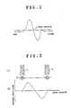
- the tracking error signal represents such a waveform as sinusoidal waveform as shown in Fig. 3B.
- the level of the tracking error signal is proportional to the offset of the beam spot S1 from the record track T and the zero-crossing points correspond to the center of each record track T and to the mid position between tracks.
- the tracking error signal and focus error signal are respectively supplied to analog VCAs (Voltage Controlled Amplifiers) 9 and 10 with a variable gain through respective LPFs (Low-pass Filters) 7 and 8 which attenuate the unnecessary frequency components equal to or above the sampling frequency used in A/D (Analog/Digital) conversion to be described later.
- the gains in the VCAs 9 and 10 are variable roughly in, for example, four stages using two bits.
- the error signals having passed the respective VCAs 9 and 10 are supplied via select switches SW1 and SW2 to an A/D converter 11 to be digitized.
- the error signals digitized in the A/D converter 11 are supplied via respective digital VCAs 12 and 13 to a digital equalizer (EQ) 16.
- the gains in the VCAs 12 and 13 can be finely varied in, for example, 16 stages using four bits.
- the individual error signals, subjected to compensation for the frequency characteristic in the equalizer 16, are converted into analog signals by a D/A (Digital/Analog) converter 17.
- the analog signals are then supplied via respective loop switches SW3 and SW4 and adders 14 and 15 adders 14 and 15 to drivers 18 and 19 to be turned into drive signals respectively for the tracking actuator and focus actuator incorporated in the pickup.
- the above-described arrangement constitutes digital servo loops for subjecting the individual error signals to A/D conversion for digital processing.
- Each servo system is controlled by a servo controller 20 comprising a microcomputer. This servo controller 20 controls the OFF(open) and ON (closed) of the loop switches SW3 and SW4 to open and close each servo loop.
- the servo controller 20 acquires a p-p value of the error signals through the VCAs 9 and 10, which are generated by supplying, for example, sinusoidal wave signals outputted as drive signals from a drive signal generator 21 to the adders 14 and 15, and sets the gains of the VCAs 9 and 10 in accordance with the p-p value to thereby coarsely adjust the loop gain of each servo loop.
- the servo controller 20 acquires a p-p value of the error signals as inputs to the D/A converter 17, and sets the gains of the VCAs 12 and 13 in accordance with the p-p value to thereby finely adjust the loop gain of each servo loop.
- sinusoidal wave signals or the like for forcibly moving the information reading spot S1 in the radial direction of the disk are outputted as drive signals to the adders 14 and 15 from the drive signal generator 21 in the tracking servo system; and sinusoidal wave signals or the like for moving the objective lens up and down with respect to the focus position are outputted as drive signals to these adders from the generator 21 in the focus servo system.
- the processor renders the loop switches SW3 and SW4 off to set each servo loop in an open state (step S1), renders the select switches SW1 and SW2 off (step S2), starts a timer I set with a predetermined time T1 (step S3), and then repeats a subroutine of latching a focus error signal having passed the VCA 10 to compute its p-p value (step S4) until the time set in the timer I is judged to have elapsed (step S5).
- the processor Upon elapse of the set time, the processor performs such a control as to set the gain of the VCA 10 to a value corresponding to the p-p value of the focus error signal acquired by the subroutine of step S4 (step S6).
- the objective lens is forcibly moved up and down by a lens drive signal to generate a focus error signal by moving the objective lens upward to the focus position and supplying a disturbance signal such as a sinusoidal wave signal to the lens drive signal.
- the processor renders the select switch SW2 on (step S7), leads the focus servo in (step S8), and, when the leading of the focus servo is completed (step S9) then renders the loop switch SW4 on to close the focus servo loop (step S10).
- the processor activates a spindle motor which is not shown (step S11) and takes a wait time of A (about 200 msec) required for the tracking error signal to be stable (step S12).
- the processor then starts a timer II set with a predetermined time T2 (step S13), and then repeats a subroutine of latching the tracking error signal originating from the eccentricity or the like of the disk from the output stage of the VCA 9 and computing its p-p value (step S14) until the time set in the timer II is judged to have elapsed (step S15).
- the processor performs such a control as to set the gain of the VCA 9 to a value corresponding to the p-p value of the tracking error signal acquired by the subroutine of step S14 (step S16).
- the tracking error signal originating from the eccentricity of the disk may be latched in a free state without driving the information reading spot S1.
- the eccentricity of the disk is zero, however, the tracking error signal will not be generated, or when the eccentricity if present is small, it takes a great deal of time to latch data. In this respect, therefore, it is practical to apply a disturbance, such as a sinusoidal wave signal, to forcibly vibrate the information reading spot S1, thereby positively generating a tracking error signal.
- the processor controls the drive signal generator 21 to apply a sinusoidal wave signal or the like as a disturbance signal, to the drive signal to move the objective lens up and down with respect to the focus position of the disk (step S17), starts a timer III set with a predetermined time T3 (step S18), and then repeats a subroutine of latching a focus error signal at the input stage of the D/A converter 17 and computing its p-p value (step S19) until the time set in the timer III is judged to have elapsed (step S20).
- the processor controls the drive signal generator 21 to stop generating the ramp signal (step S21), and then performs such a control as to set the gain of the VCA 13 to a value corresponding to the p-p value of the focus error signal acquired by the subroutine of step S19 (step S22).
- the processor then renders the select switch SW1 on (step S23), and then renders the loop switch SW3 on to close the tracking servo loop (step S24). Subsequently, the processor controls the drive signal generator 21 to apply a sinusoidal wave signal or the like as a disturbance signal to move the information reading spot S1 in the radial direction of the disk (step S25), starts a timer IV set with a predetermined time T4 (step S26), and then repeats a subroutine of latching a tracking error signal at the input stage of the D/A converter 17 and computing its p-p value (step S27) until the time set in the timer IV is judged to have elapsed (step S28).
- the processor Upon elapse of the set time, the processor-controls the drive signal generator 21 to stop generating the sinusoidal wave signal (step S29), and then performs such a control as to set the gain of the VCA 12 to a value corresponding to the p-p value of the tracking error signal acquired by the subroutine of step S27 (step S30).
- step S29 the processor-controls the drive signal generator 21 to stop generating the sinusoidal wave signal
- step S30 performs such a control as to set the gain of the VCA 12 to a value corresponding to the p-p value of the tracking error signal acquired by the subroutine of step S27.
- the method of computing the p-p values of the focus error signals in the subroutines of steps S4 and S19 and the method of computing the p-p values of the tracking error signals in the subroutines of steps S14 and S27 may be, for example, those disclosed in Published Unexamined Japanese Patent Application No. Sho-63-106003.
- each servo loop can, without failure, be set in the closed state by coarsely adjusting in advance the loop gain of the servo loop in the open state, so that automatic control of the loop gain in the closed state can be surely and accurately be executed even if there is a variation in reflection factor of the disk or a stain or the like on the objective lens.
- VCAs 9 and i0 are provided at the preceding stage of the A/D converter 11 to execute the coarse adjustment of the loop gain in an analog stage in the above-described embodiment
- the VCAs 9 and 10 may be provided at the subsequent stage of the A/D converter 11 to coarsely adjust the loop gain in a digital stage.
- a phase comparator 23 may be provided as shown in Fig. 5 to detect the phase difference between a drive signal applied as a disturbance and a disturbance signal extracted from the output of the digital equalizer 16 by a BPF (Band-path Filter) 22, so that the gain control of the VCAs 9 and 10 can be executed in accordance with the phase difference.
- BPF Band-path Filter
- a simple type of feedback control system is illustrated in the block diagram of Fig. 6 in which R(s) is a reference input signal, C(s) the amount of control, and E(s) an offset or the difference between R(s)and C(s).
- the feedback control system applies the gain of G(s) based on the E(s), and the transfer function of the closed loop is defined as follows:
- the gain G and phase ⁇ are defined as follows: and are illustrated in a graph as shown in Fig. 7.
- the gain for a compact disk is designed to be, for example, 0 dB at 1 KHz according to the closed loop characteristic, for example, the gain is controlled in accordance with the magnitude of the error signal level between the added disturbance signal (e.g., a sinusoidal wave of 1 KHz) and the signal extracted by the BPF 22.
- the added disturbance signal e.g., a sinusoidal wave of 1 KHz
- each loop gain may as well be finely adjusted by controlling the gains of the VCAs 9 and 10 in such a way that a sinusoidal wave of a specific frequency (e.g., 1.5 KHz) is added as a disturbance in the loop to be added to the output of the equalizer 16 in the closed loop state so as to be reference value (e.g., -90 deg) at the designed value of 1.5 KHz) and the phase difference between the disturbance sinusoidal wave and a disturbance sinusoidal wave extracted from the output of the equalizer 16 by the BPF 22 becomes the reference value (e.g., -90 deg), as shown in Fig. 5.
- a sinusoidal wave of a specific frequency e.g. 1.5 KHz
- the servo apparatus for an optical disk player is designed to execute coarse adjustment of the loop gain in advance in the open state of the servo loop, and then set the servo loop in a closed state to finely adjust the loop gain, so that automatic control of the loop gain can surely and accurately be executed even if there is a variation in reflection factor of a disk or a stain or the like on the objective lens.
Landscapes
- Optical Recording Or Reproduction (AREA)
Abstract
Description
- The present invention relates to a servo apparatus for an optical disk player.
- Disk players of, for examle, optical type which play information-recorded disks, such as a video disk and digital audio disk (hereinafter simply referred to as disk) inevitably require a focus servo apparatus for converging a light beam on the information-recorded surface of a disk to form an information reading light spot and a tracking servo apparatus for permitting the information reading light spot to accurately track record tracks on the disk.
- As the focus servo apparatus, there is, for example, a known apparatus employing a so-called astigmatism method, which uses a cylindrical lens to converge light beams as a single light beam in a horizontal direction on one of two points separated on the light path of the light beams and converge the light beams as a single vertical beam on the other point, and generates a focus error signal based on the foursome output of a four-split light detector disposed in the middle of the mentioned two points.
- As the tracking servo apparatus, there has been known, for example, an apparatus employing a so-called 3-beam method which arranges three beams, namely, an information reading main beam and two sub-beams for detection of a tracking error, located on the respective sides of the main beam, in such a manner that lines connecting the optical axes of the three beams have predetermined offset angles to the direction of a tangent line to the tracks, and generates an error signal based on the difference between the amounts of light of two sub-beams which have passed the information-recorded surface of a disk.
- The loop gains of the servo loops of these servo apparatuses may vary due to a variation in reflection factor, a variation in power of a light beam caused by a stain or the like on an objective lens or a variation in sensitivity of a photosensor in a pickup. This variation in loop gain reduces the follow-up performance with respect to the focus error and tracking error, making it difficult to provide a stable servo operation.
- In this respect, an automatic gain control is executed for each disk to acquire the optimal loop gain at the time the disk is played. For instance, in automatically controlling the gain of the focus servo loop of, for example, a video disk player, the loop gain is set in advance lower than the one for the normal playing, and the servo is led in to close the loop before controlling the gain. This control method cannot automatically control the loop gain when the focus servo loop cannot be closed due to a variation in reflection factor of the disk or a stain or the like on the objective lens.
- Since a variation in tracking error signal is too large to close the servo loop in the tracking servo apparatus, the p-p value of a tracking error signal (the difference between positive and negative peaks) in an open status is detected and the gain control is executed in accordance with this p-p value. As this method performs the gain control with the servo loop in the open status, it is easily influenced by the eccentricity of the disk and is therefore apt to cause a variation in the control value.
- It is therefore an object of the present invention to provide a servo apparatus for an optical disk player, which can surely and accurately execute automatic control of the loop gain even if there exists a variation in reflection factor of a disk or a stain or the like on an objective lens.
- To achieve this object, according to the present invention, there is provided a servo apparatus for an optical disk player, having a signal generator means for generating a predetermined error signal based on an output signal of a pickup for reading recorded information from a disk and including a servo loop controllable to be selectively opened or closed and, in a closed state thereof, driving the pickup based on the error signal, the servo apparatus comprising a loop gain coarse adjustment means for coarsely adjusting a loop gain of the servo loop in an open state thereof; and a loop gain fine adjustment means for finely adjusting the loop gain in the closed state of the servo loop.
- According to the servo apparatus for an optical disk player embodying the present invention, the loop gain is coarsely adjusted in advance in the open state of the servo loop, and then the servo loop is set in the closed state to perform a fine adjustment of the loop gain.
-
- Fig. 1 is a block diagram illustrating the structure of a servo apparatus for an optical disk player according to the present invention;
- Fig. 2 is a waveform diagram showing a change in waveform of a focus error signal with respect to the distance of an objective lens from the disk surface;
- Fig. 3 is a diagram illustrating the relation between the positions of information reading spot with respect to record tracks and a tracking error signal;
- Fig. 4 is a flowchart illustrating procedures for coarse and fine loop gain adjustments;
- Fig. 5 is a block diagram showing another embodiment of the present invention;
- Fig. 6 is a block diagram of a feedback control system; and
- Fig. 7 is a diagram illustrating a transfer characteristic of a closed loop.
- Preferred embodiments of this invention will now be described in detail with reference to the accompanying drawings.
- Fig. 1 is a block diagram illustrating the structure of a servo apparatus for an optical disk player according to the present invention. Referring to this diagram, three beam spots acquired by converging a laser beam, namely, an information reading spot (information reading point) S₁ and a pair of tracking error detection spots S₂ and S₃, respectively preceding and following the spot S₁ at the time the spot S₁ moves relative to the rotational direction of a disk (not shown), are emitted on a record track T on the disk from a pickup (not shown) with the illustrated positional relationship. The reflection lights from the disk originating from these beam spots respectively enter photoelectric converting elements 1 to 3 incorporated in the pickup to be converted into electric signals. The pickup also has therein a focus actuator for controlling the position of an objective lens in the direction of the optical axis with respect to the information-recorded surface of the disk and a tracking actuator for controlling the position of a beam spot in the radial direction of the disk with respect to the record track T, in addition to an optical system including the objective lens. This pickup is supported by a carriage (not shown) which is freely movable in the radial direction of the disk.
- The photoelectric converting element 1 comprises four light receiving elements, which are arranged to have the light receiving surfaces divided into four sections and are dependent of one another. The sum of the outputs of those two light receiving elements which face each other with respect to the center of the light receiving surfaces is sent to a
differential amplifier 4, and the sum of the outputs of the other pair of facing elements is likewise sent to theamplifier 4. Theamplifier 4 outputs a signal representing the difference between the two sums, this difference signal being a focus error (FE) signal. This focus error signal shows a so-called S curve characteristic which zero-crosses at a focus position with respect to the distance of the objective lens away from the disk surface as the objective lens moves up and down with respect to the focus position, as shown in Fig. 2. The sums of the outputs mentioned above are also supplied to an adder 5 which provides a signal representing the sum of the received sums or a total sum signal of the individual light receiving elements, this total sum signal being a read RF signal. - On the other hand, the outputs of the
photoelectric converting elements 2 and 3 are supplied to a differential amplifier 6 which provides a difference signal of the received outputs, this difference signal being a tracking error (TE) signal. With the tracking servo loop in an open state, when the beam spot S₁ moves from one record track T₁ to an adjoining record track T₂ as shown in Fig. 3A, the tracking error signal represents such a waveform as sinusoidal waveform as shown in Fig. 3B. The level of the tracking error signal is proportional to the offset of the beam spot S₁ from the record track T and the zero-crossing points correspond to the center of each record track T and to the mid position between tracks. - The tracking error signal and focus error signal are respectively supplied to analog VCAs (Voltage Controlled Amplifiers) 9 and 10 with a variable gain through respective LPFs (Low-pass Filters) 7 and 8 which attenuate the unnecessary frequency components equal to or above the sampling frequency used in A/D (Analog/Digital) conversion to be described later. The gains in the
VCAs respective VCAs D converter 11 to be digitized. The error signals digitized in the A/D converter 11 are supplied via respectivedigital VCAs VCAs equalizer 16, are converted into analog signals by a D/A (Digital/Analog)converter 17. The analog signals are then supplied via respective loop switches SW₃ and SW₄ andadders adders drivers 18 and 19 to be turned into drive signals respectively for the tracking actuator and focus actuator incorporated in the pickup. - The above-described arrangement constitutes digital servo loops for subjecting the individual error signals to A/D conversion for digital processing. Each servo system is controlled by a
servo controller 20 comprising a microcomputer. Thisservo controller 20 controls the OFF(open) and ON (closed) of the loop switches SW₃ and SW₄ to open and close each servo loop. In addition, with each servo loop in the open state, theservo controller 20 acquires a p-p value of the error signals through theVCAs drive signal generator 21 to theadders VCAs servo controller 20 acquires a p-p value of the error signals as inputs to the D/A converter 17, and sets the gains of theVCAs - In finely controlling the loop gain, sinusoidal wave signals or the like for forcibly moving the information reading spot S₁ in the radial direction of the disk are outputted as drive signals to the
adders drive signal generator 21 in the tracking servo system; and sinusoidal wave signals or the like for moving the objective lens up and down with respect to the focus position are outputted as drive signals to these adders from thegenerator 21 in the focus servo system. - Next, a sequence of processes executed by the processor of the
servo controller 20 for coarse and fine adjustments of the loop gain will be described below referring to the flowchart shown in Fig. 4. It should be noted that this routine is invoked and executed every time a disk is played. - First, the processor renders the loop switches SW₃ and SW₄ off to set each servo loop in an open state (step S1), renders the select switches SW₁ and SW₂ off (step S2), starts a timer I set with a predetermined time T₁ (step S3), and then repeats a subroutine of latching a focus error signal having passed the
VCA 10 to compute its p-p value (step S4) until the time set in the timer I is judged to have elapsed (step S5). Upon elapse of the set time, the processor performs such a control as to set the gain of theVCA 10 to a value corresponding to the p-p value of the focus error signal acquired by the subroutine of step S4 (step S6). Through the above processing, the coarse adjustment of the loop gain of the focus servo loop is completed. - In executing the coarse adjustment of the loop gain of the focus servo loop, since the lens position of the pickup and the reflection position on a disk when the focus servo loop is open vary depending on pickups and disks in use, the objective lens is forcibly moved up and down by a lens drive signal to generate a focus error signal by moving the objective lens upward to the focus position and supplying a disturbance signal such as a sinusoidal wave signal to the lens drive signal.
- Next, the processor renders the select switch SW₂ on (step S7), leads the focus servo in (step S8), and, when the leading of the focus servo is completed (step S9) then renders the loop switch SW₄ on to close the focus servo loop (step S10). Subsequently, the processor activates a spindle motor which is not shown (step S11) and takes a wait time of A (about 200 msec) required for the tracking error signal to be stable (step S12).
- The processor then starts a timer II set with a predetermined time T₂ (step S13), and then repeats a subroutine of latching the tracking error signal originating from the eccentricity or the like of the disk from the output stage of the
VCA 9 and computing its p-p value (step S14) until the time set in the timer II is judged to have elapsed (step S15). Upon elapse of the set time, the processor performs such a control as to set the gain of theVCA 9 to a value corresponding to the p-p value of the tracking error signal acquired by the subroutine of step S14 (step S16). Through the above processing, the coarse adjustment of the loop gain of the tracking servo loop is completed. - In executing the coarse adjustment of the loop gain of the tracking servo loop, the tracking error signal originating from the eccentricity of the disk may be latched in a free state without driving the information reading spot S₁. When the eccentricity of the disk is zero, however, the tracking error signal will not be generated, or when the eccentricity if present is small, it takes a great deal of time to latch data. In this respect, therefore, it is practical to apply a disturbance, such as a sinusoidal wave signal, to forcibly vibrate the information reading spot S₁, thereby positively generating a tracking error signal.
- Next, the processor controls the
drive signal generator 21 to apply a sinusoidal wave signal or the like as a disturbance signal, to the drive signal to move the objective lens up and down with respect to the focus position of the disk (step S17), starts a timer III set with a predetermined time T₃ (step S18), and then repeats a subroutine of latching a focus error signal at the input stage of the D/A converter 17 and computing its p-p value (step S19) until the time set in the timer III is judged to have elapsed (step S20). Upon elapse of the set time, the processor controls thedrive signal generator 21 to stop generating the ramp signal (step S21), and then performs such a control as to set the gain of theVCA 13 to a value corresponding to the p-p value of the focus error signal acquired by the subroutine of step S19 (step S22). Through the above processing, the fine adjustment of the loop gain of the focus servo loop is completed. - The processor then renders the select switch SW₁ on (step S23), and then renders the loop switch SW₃ on to close the tracking servo loop (step S24). Subsequently, the processor controls the
drive signal generator 21 to apply a sinusoidal wave signal or the like as a disturbance signal to move the information reading spot S₁ in the radial direction of the disk (step S25), starts a timer IV set with a predetermined time T₄ (step S26), and then repeats a subroutine of latching a tracking error signal at the input stage of the D/A converter 17 and computing its p-p value (step S27) until the time set in the timer IV is judged to have elapsed (step S28). Upon elapse of the set time, the processor-controls thedrive signal generator 21 to stop generating the sinusoidal wave signal (step S29), and then performs such a control as to set the gain of theVCA 12 to a value corresponding to the p-p value of the tracking error signal acquired by the subroutine of step S27 (step S30). Through the above processing, the fine adjustment of the loop gain of the tracking servo loop is completed. - The method of computing the p-p values of the focus error signals in the subroutines of steps S4 and S19 and the method of computing the p-p values of the tracking error signals in the subroutines of steps S14 and S27 may be, for example, those disclosed in Published Unexamined Japanese Patent Application No. Sho-63-106003.
- As described above, each servo loop can, without failure, be set in the closed state by coarsely adjusting in advance the loop gain of the servo loop in the open state, so that automatic control of the loop gain in the closed state can be surely and accurately be executed even if there is a variation in reflection factor of the disk or a stain or the like on the objective lens.
- Although the above embodiment has been described with reference to a case where the tracking gain is coarsely adjusted after the coarse adjustment of the focus gain, the similar effect may be obtained by conducting the fine adjustment of the focus gain after the coarse adjustment of the focus gain.
- In addition, although the VCAs 9 and i0 are provided at the preceding stage of the A/
D converter 11 to execute the coarse adjustment of the loop gain in an analog stage in the above-described embodiment, the VCAs 9 and 10 may be provided at the subsequent stage of the A/D converter 11 to coarsely adjust the loop gain in a digital stage. - Further, although a method of computing the amount of control in the coarse adjustment of the VCAs 9 and 10 in the analog stage has been explained in the foregoing embodiment, the same may be computed based on digital data acquired from the output of the A/
D converter 11 by rendering the select switches SW₁ and SW₂ on. - Moreover, although a method of setting the fine adjustment of each loop gain through gain control of the VCAs 9 and 10 based on the p-p value of each error signal has been explained in the foregoing embodiment, a
phase comparator 23 may be provided as shown in Fig. 5 to detect the phase difference between a drive signal applied as a disturbance and a disturbance signal extracted from the output of thedigital equalizer 16 by a BPF (Band-path Filter) 22, so that the gain control of the VCAs 9 and 10 can be executed in accordance with the phase difference. - The principle of such a gain control will be described below.
- A simple type of feedback control system is illustrated in the block diagram of Fig. 6 in which R(s) is a reference input signal, C(s) the amount of control, and E(s) an offset or the difference between R(s)and C(s). The feedback control system applies the gain of G(s) based on the E(s), and the transfer function of the closed loop is defined as follows:

- In the transfer characteristic of the closed loop, the gain G and phase φ are defined as follows:

and are illustrated in a graph as shown in Fig. 7. - In the case where the fine adjustment is performed based on the p-p value of the error signal, as the gain for a compact disk is designed to be, for example, 0 dB at 1 KHz according to the closed loop characteristic, for example, the gain is controlled in accordance with the magnitude of the error signal level between the added disturbance signal (e.g., a sinusoidal wave of 1 KHz) and the signal extracted by the
BPF 22. - In the case of executing the gain control based on the phase difference instead of the p-p value of the error signal, therefore, each loop gain may as well be finely adjusted by controlling the gains of the VCAs 9 and 10 in such a way that a sinusoidal wave of a specific frequency (e.g., 1.5 KHz) is added as a disturbance in the loop to be added to the output of the
equalizer 16 in the closed loop state so as to be reference value (e.g., -90 deg) at the designed value of 1.5 KHz) and the phase difference between the disturbance sinusoidal wave and a disturbance sinusoidal wave extracted from the output of theequalizer 16 by theBPF 22 becomes the reference value (e.g., -90 deg), as shown in Fig. 5. - As described above, the servo apparatus for an optical disk player according to the present invention is designed to execute coarse adjustment of the loop gain in advance in the open state of the servo loop, and then set the servo loop in a closed state to finely adjust the loop gain, so that automatic control of the loop gain can surely and accurately be executed even if there is a variation in reflection factor of a disk or a stain or the like on the objective lens.
Claims (7)
- A servo apparatus for an optical disk player, having a signal generator means for generating a predetermined error signal based on an output signal of a pickup for reading recorded information from an information-recorded disk and including a servo loop controllable to be selectively opened or closed and, in a closed state thereof, driving the pickup based on the error signal, the servo apparatus comprising:
a loop gain coarse adjustment means for coarsely adjusting a loop gain of the servo loop in an open state thereof; and
a loop gain fine adjustment means for finely adjusting the loop gain in the closed state of the servo loop. - A servo apparatus for an optical disk player according to Claim 1, wherein loop gain adjustments are conducted by the loop gain coarse adjusting means and the loop gain fine adjusting means every time the information-recorded disk is played.
- A servo apparatus for an optical disk player according to Claim 1, wherein the loop gain coarse adjustment means includes a variable gain amplifier for amplifying an error signal produced by the signal generator means, and a gain control means for detecting an amplitude of the error signal amplified by the variable gain amplifier and controlling a gain of the variable gain amplifier in accordance with a level of the amplitude of the error signal detected.
- A servo apparatus for an optical disk player according to Claim 1, wherein the predetermined error signal is a focus error signal, and wherein the loop gain fine adjustment means includes a variable gain amplifier for amplifying a focus error signal having passed the loop gain coarse adjusting means, a means for generating a drive signal to move an objective lens in the pickup up and down with respect to a focus position of the objective lens, and a gain control means for detecting an amplitude of the focus error signal amplified by the variable gain amplifier at a time of driving in response to the drive signal and controlling a gain of the variable gain amplifier in accordance with a level of the amplitude of the focus error signal detected.
- A servo apparatus for an optical disk player according to Claim 1, wherein the predetermined error signal is a tracking error signal, and wherein the loop gain fine adjustment means includes a variable gain amplifier for amplifying a tracking error signal having passed the loop gain coarse adjusting means, a means for generating a drive signal to move an information reading point of the pickup in a radial direction of the disk, and a gain control means for detecting an amplitude of the tracking error signal amplified by the variable gain amplifier at a time of driving in response to the drive signal and controlling a gain of the variable gain amplifier in accordance with a level of the amplitude of the tracking error signal detected.
- A servo apparatus for an optical disk player according to Claim 1, wherein the predetermined error signal is a focus error signal, and wherein the loop gain fine adjustment means includes a variable gain amplifier for amplifying a focus error signal having passed the loop gain coarse adjusting means, a means for generating a drive signal to move an objective lens in the pickup up and down with respect to a focus position of the objective lens, and a gain control means for detecting a phase difference between the focus error signal amplified by the variable gain amplifier at a time of driving in response to the drive signal and the drive signal, and controlling a gain of the variable gain amplifier in accordance with the phase difference detected.
- A servo apparatus for an optical disk player according to Claim 1, wherein the predetermined error signal is a tracking error signal, and wherein the loop gain fine adjustment means includes a variable gain amplifier for amplifying a tracking error signal having passed the loop gain coarse adjustment means, a means for generating a drive signal to move an information reading point of the pickup in a radial direction of the disk, and a gain control means for detecting a phase difference between the tracking error signal amplified by the variable gain amplifier at a time of driving in response to the drive signal and the drive signal, and controlling a gain of the variable gain amplifier in accordance with the phase difference detected.
Applications Claiming Priority (2)
| Application Number | Priority Date | Filing Date | Title |
|---|---|---|---|
| JP62423/90 | 1990-03-13 | ||
| JP2062423A JPH03263620A (en) | 1990-03-13 | 1990-03-13 | Servo device for disk player |
Publications (3)
| Publication Number | Publication Date |
|---|---|
| EP0446412A2 true EP0446412A2 (en) | 1991-09-18 |
| EP0446412A3 EP0446412A3 (en) | 1992-04-29 |
| EP0446412B1 EP0446412B1 (en) | 1996-02-07 |
Family
ID=13199733
Family Applications (1)
| Application Number | Title | Priority Date | Filing Date |
|---|---|---|---|
| EP90119302A Expired - Lifetime EP0446412B1 (en) | 1990-03-13 | 1990-10-09 | Servo apparatus for optical disk player |
Country Status (4)
| Country | Link |
|---|---|
| US (1) | US5146443A (en) |
| EP (1) | EP0446412B1 (en) |
| JP (1) | JPH03263620A (en) |
| DE (1) | DE69025314T2 (en) |
Cited By (5)
| Publication number | Priority date | Publication date | Assignee | Title |
|---|---|---|---|---|
| EP0565376A1 (en) * | 1992-04-10 | 1993-10-13 | Canon Kabushiki Kaisha | Optical information recording apparatus and method capable of coping with a plurality of card-like recording mediums of different reflectances |
| EP0547630A3 (en) * | 1991-12-18 | 1994-09-07 | Hewlett Packard Co | Adaptive control system for a disk drive actuator |
| FR2708778A1 (en) * | 1993-07-31 | 1995-02-10 | Samsung Electronics Co Ltd | Focus control device for an optical disc system. |
| EP1017051A3 (en) * | 1998-11-19 | 2002-02-06 | Pioneer Corporation | Gain controlling apparatus and method, information reproducing apparatus and method, and information recording apparatus and method |
| WO2008001298A2 (en) | 2006-06-26 | 2008-01-03 | Koninklijke Philips Electronics N.V. | Disc drive and photo-detector circuits |
Families Citing this family (74)
| Publication number | Priority date | Publication date | Assignee | Title |
|---|---|---|---|---|
| US5265079A (en) | 1991-02-15 | 1993-11-23 | Applied Magnetics Corporation | Seek actuator for optical recording |
| US6141300A (en) | 1989-06-20 | 2000-10-31 | Discovision Associates | Optical actuator including lens assembly with optical axis having symmetric suspensory forces acting thereon and optical disc system including same |
| US5293365A (en) * | 1990-05-30 | 1994-03-08 | Olympus Optical Co., Ltd. | Track control circuit for optical card recording/reproducing apparatus |
| US6236625B1 (en) * | 1991-02-15 | 2001-05-22 | Discovision Associates | Optical disc system having current monitoring circuit with controller for laser driver and method for operating same |
| US5729511A (en) | 1991-02-15 | 1998-03-17 | Discovision Associates | Optical disc system having servo motor and servo error detection assembly operated relative to monitored quad sum signal |
| US5677899A (en) | 1991-02-15 | 1997-10-14 | Discovision Associates | Method for moving carriage assembly from initial position to target position relative to storage medium |
| US6069857A (en) | 1991-02-15 | 2000-05-30 | Discovision Associates | Optical disc system having improved circuitry for performing blank sector check on readable disc |
| JPH04265530A (en) * | 1991-02-19 | 1992-09-21 | Oki Electric Ind Co Ltd | Optical disk device |
| JP2807118B2 (en) * | 1992-02-27 | 1998-10-08 | 富士通株式会社 | Optical disk drive |
| JPH05307848A (en) * | 1992-05-01 | 1993-11-19 | Ricoh Co Ltd | Closed loop control system and servo device for optical disk device |
| JPH0668498A (en) * | 1992-08-24 | 1994-03-11 | Toshiba Corp | Information recording medium processor |
| JPH06243496A (en) * | 1993-02-15 | 1994-09-02 | Toshiba Corp | Disk reproducer and its focus balance automatic adjustment method and signal processor |
| DE4323067A1 (en) * | 1993-07-10 | 1995-01-12 | Thomson Brandt Gmbh | G factor adjustment |
| US5446716A (en) * | 1994-01-10 | 1995-08-29 | Eastman Kodak Company | Laser power control in an optical recording system to compensate for multiple system degradations |
| US5436880A (en) * | 1994-01-10 | 1995-07-25 | Eastman Kodak Company | Laser power control in an optical recording system using partial correction of reflected signal error |
| US5748578A (en) | 1995-01-25 | 1998-05-05 | Discovision Associates | Colpitts type oscillator having reduced ringing and improved optical disc system utilizing same |
| US6091684A (en) | 1995-01-25 | 2000-07-18 | Discovision Associates | Optical disc system and method for changing the rotational rate of an information storage medium |
| US6434087B1 (en) | 1995-01-25 | 2002-08-13 | Discovision Associates | Optical disc system and method for controlling bias coil and light source to process information on a storage medium |
| KR100211841B1 (en) * | 1997-05-19 | 1999-08-02 | 윤종용 | Automatic gain adjusting apparatus and method for a sled motor in a digital video disc player |
| JP3869998B2 (en) * | 2000-03-24 | 2007-01-17 | パイオニア株式会社 | Carriage servo device and information reproducing device |
| JP3714458B2 (en) * | 2000-04-28 | 2005-11-09 | パイオニア株式会社 | Servo control device for optical disc player |
| US7095683B2 (en) * | 2001-01-25 | 2006-08-22 | Dphi Acquisitions, Inc. | Tracking and focus digital servo system with write abort |
| US6891789B2 (en) * | 2001-01-25 | 2005-05-10 | Dphi Acquisitions, Inc. | Tracking and focus servo system with automatic media type detector |
| US6738320B2 (en) | 2001-01-25 | 2004-05-18 | Dphi Acquisitions, Inc. | System and method for moving optical pick up from current position to target position with smooth control |
| US6781929B2 (en) | 2001-01-25 | 2004-08-24 | Dphi Acquisitions, Inc. | Digital tracking servo system with multi-track seek |
| US7092322B2 (en) * | 2001-01-25 | 2006-08-15 | Dphi Acquisitions, Inc. | Calibration of focus error signal offset in a focus servo system |
| US7680004B2 (en) * | 2001-01-25 | 2010-03-16 | Dphi Acquisitions, Inc. | Digital servo system with inverse non-linearity compensation |
| US6813226B2 (en) | 2001-01-25 | 2004-11-02 | Dphi Acquisitions, Inc. | Calibration of a focus sum threshold in a focus servo system |
| US6891781B2 (en) * | 2001-01-25 | 2005-05-10 | Dphi Acquisitions, Inc. | Digital servo system with second order compensator |
| US7522480B2 (en) | 2001-01-25 | 2009-04-21 | Dphi Acquisitions, Inc. | Digital tracking servo system with multi-track seek with an acceleration clamp |
| US6937543B2 (en) | 2001-01-25 | 2005-08-30 | Dphi Acquisitions, Inc. | Digital focus servo system with a sliding notch filter |
| US6898164B2 (en) | 2001-01-25 | 2005-05-24 | Dphi Acquisitions, Inc. | Close tracking algorithm in a digital tracking servo system |
| US7023766B2 (en) | 2001-01-25 | 2006-04-04 | Dphi Acquisitions, Inc. | Flexible servicing of servo algorithms using a digital signal processor |
| US6882603B2 (en) * | 2001-01-25 | 2005-04-19 | Dphi Acquisitions, Inc. | Digital tracking servo system with tracking skate detection |
| US6970403B2 (en) * | 2001-01-25 | 2005-11-29 | Dphi Acquisition, Inc. | Calibration of tracking error signal offset in a tracking servo system |
| US7260031B2 (en) | 2001-01-25 | 2007-08-21 | Dphi Acquisitions, Inc. | Digital focus and tracking servo system with one-track jump |
| US6958957B2 (en) * | 2001-01-25 | 2005-10-25 | Dphi Acquisitions, Inc. | Digital tracking and focus servo system with TES to FES crosstalk calibration |
| US6950380B2 (en) * | 2001-01-25 | 2005-09-27 | Dphi Acquisitions, Inc. | Detector input dark current offset calibration in an optical disk drive digital servo |
| US6970410B2 (en) * | 2001-01-25 | 2005-11-29 | Dphi Acquisitions, Inc. | Focus detection in a digital focus servo system |
| US6909676B2 (en) | 2001-01-25 | 2005-06-21 | Dphi Acquisitions, Inc. | Digital tracking servo system with multi-track seek with track zero crossing detection |
| US6882601B2 (en) | 2001-01-25 | 2005-04-19 | Dphi Acquisitions, Inc. | Digital servo system with feed-forward control loops |
| US6847597B2 (en) | 2001-01-25 | 2005-01-25 | Dphi Acquisitions, Inc. | Optical disk drive with a digital focus and tracking servo system |
| US6885619B2 (en) | 2001-01-25 | 2005-04-26 | Dphi Acquisitions, Inc. | Detector input stray light offset calibration in an optical disk drive |
| US7196979B2 (en) | 2001-01-25 | 2007-03-27 | Dphi Acquisitions, Inc. | Calibration storage methods for a digital focus and tracking servo system with calibration |
| US7672199B2 (en) | 2001-01-25 | 2010-03-02 | Dphi Acquisitions, Inc. | Close focus algorithm in a digital focus servo system |
| US6813228B2 (en) | 2001-01-25 | 2004-11-02 | Dphi Acquisitions, Inc. | Tracking and focus servo system with direction sensor |
| US20020131338A1 (en) * | 2001-01-25 | 2002-09-19 | Turner Christopher J. | System and method for controlling operation of a disc drive for optical media with premastered and read/write sectors |
| US6906985B2 (en) | 2001-01-25 | 2005-06-14 | Dphi Acquisitions, Inc. | Calibration of tracking error signal gain in a tracking servo system |
| US7414940B2 (en) | 2001-01-25 | 2008-08-19 | Dphi Acquisitions, Inc. | Calibration of a focus error signal gain in a focus servo system |
| US6965547B2 (en) * | 2001-01-25 | 2005-11-15 | Dphi Acquisitions, Inc. | Tracking and focus servo system with error signal inverse non-linearity calibration |
| US7593300B2 (en) | 2001-01-25 | 2009-09-22 | Dphi Acquisitions, Inc. | Digital tracking servo system with off-format detection |
| US7023776B2 (en) * | 2001-01-25 | 2006-04-04 | Dphi Acquisitions, Inc. | Calibration initiation methods for a tracking and focus servo system |
| US6847596B2 (en) | 2001-01-25 | 2005-01-25 | Dphi Acquisitions, Inc. | Tracking servo system including a multi-track seek algorithm with a track zero crossing period integrity test |
| US6930963B2 (en) * | 2001-01-25 | 2005-08-16 | Dphi Acquistions, Inc. | Tracking and focus servo system with head load |
| US6809995B2 (en) | 2001-01-25 | 2004-10-26 | Dphi Acquisitions, Inc. | Digital focus and tracking servo system |
| US7020054B2 (en) * | 2001-01-25 | 2006-03-28 | Dphi Acquisitions, Inc. | Digital servo system with biased feed-forward |
| US7492675B2 (en) * | 2001-01-25 | 2009-02-17 | Dphi Acquisitions, Inc. | Digital servo system with calibrated notch filters |
| US6728182B2 (en) | 2001-01-25 | 2004-04-27 | Dphi Acquisitions, Inc. | Tracking and focus servo system with a media type boundary crossing detector |
| US6956797B2 (en) * | 2001-01-25 | 2005-10-18 | Dphi Acquisitions, Inc. | Digital servo system with error signal integrity testing |
| US6904007B2 (en) * | 2001-01-25 | 2005-06-07 | Dphi Acquisitions, Inc. | Digital servo system with loop gain calibration |
| US7782721B2 (en) * | 2001-01-25 | 2010-08-24 | Dphi Acquisitions, Inc. | Digital focus and tracking servo system with multi-zone calibration |
| US6704261B2 (en) | 2001-01-25 | 2004-03-09 | Dphi Acquisitions, Inc. | Spin motor control in an optical drive |
| US6762980B2 (en) | 2001-01-25 | 2004-07-13 | Dphi Acquisitions, Inc. | Digital tracking servo system with a multi-track seeking and accelerated servo function for regaining a closed tracking loop |
| US6922380B2 (en) | 2001-01-25 | 2005-07-26 | Dphi Acquisitions, Inc. | Tracking and focus servo system with anti-skate algorithm |
| US7016280B2 (en) * | 2001-01-25 | 2006-03-21 | Dphi Acquisitions, Inc. | Tracking and focus servo system with defect detection |
| JP2003151143A (en) * | 2001-11-13 | 2003-05-23 | Minebea Co Ltd | Optical information recording device |
| JP4109919B2 (en) * | 2002-07-19 | 2008-07-02 | キヤノン株式会社 | Optical information reproducing device |
| JP4077696B2 (en) | 2002-09-05 | 2008-04-16 | 松下電器産業株式会社 | Tracking control device |
| CN1310220C (en) * | 2003-11-17 | 2007-04-11 | 威盛电子股份有限公司 | Method and device for generating stable power control signal |
| TWI261226B (en) * | 2004-01-20 | 2006-09-01 | Via Tech Inc | Apparatus and method of dynamic adjusting the detection window |
| WO2006003544A1 (en) * | 2004-06-28 | 2006-01-12 | Koninklijke Philips Electronics N.V. | A method for improving robustness of optical disk readout |
| TWI261240B (en) | 2004-08-17 | 2006-09-01 | Via Tech Inc | Method for determining data storage quality of optical disc |
| US20070058502A1 (en) * | 2005-09-12 | 2007-03-15 | Chi-Pei Huang | Servo system and related method of adjusting the magnitude of detecting signals outputted from a pick-up head before utilizing the detecting signals to generate servo signals |
| WO2022080202A1 (en) * | 2020-10-15 | 2022-04-21 | パナソニックIpマネジメント株式会社 | Optical disk device and recording/playback device |
Family Cites Families (22)
| Publication number | Priority date | Publication date | Assignee | Title |
|---|---|---|---|---|
| FR675254A (en) * | 1930-02-18 | 1930-02-07 | Thomson Houston Comp Francaise | Improvements to high frequency electrical devices |
| GB388551A (en) * | 1932-01-29 | 1933-03-02 | Sunsaloon Bodies Ltd | Improvements in and relating to sliding doors |
| GB388555A (en) * | 1932-01-30 | 1933-03-02 | Cherry Tree Machine Company Lt | Improvements in and relating to rotary chamber drying machines |
| JPS57113428A (en) * | 1980-12-29 | 1982-07-14 | Pioneer Video Corp | Focus servo device |
| JPS5919249A (en) * | 1982-07-21 | 1984-01-31 | Hitachi Ltd | Servo circuit gain control device |
| JPS6132225A (en) * | 1984-07-23 | 1986-02-14 | Hitachi Ltd | Optical recording and reproducing device |
| JPS61233435A (en) * | 1985-04-09 | 1986-10-17 | Matsushita Electric Ind Co Ltd | Servo gain controller |
| JPS61233431A (en) * | 1985-04-09 | 1986-10-17 | Matsushita Electric Ind Co Ltd | Servo gain controller |
| JPS6233341A (en) * | 1985-08-06 | 1987-02-13 | Canon Inc | Optical information recording and reproducing device |
| US4701603A (en) * | 1985-10-17 | 1987-10-20 | Optical Disc Corporation | Focus control system for optical information recorder or player |
| JPS62137781A (en) * | 1985-12-10 | 1987-06-20 | Pioneer Electronic Corp | Tracking servo device |
| US4866688A (en) * | 1985-12-20 | 1989-09-12 | Hitachi, Ltd. | Composite tracking servo system for optical disc apparatus with track offset correction |
| US4878211A (en) * | 1986-05-26 | 1989-10-31 | Pioneer Electronic Corporation | Method and apparatus for correcting the loop gain of a servo loop in accordance with measurements during open-loop operation |
| JPS63106003A (en) * | 1986-05-26 | 1988-05-11 | Pioneer Electronic Corp | Method and device for correcting loop gain in fine adjusting servo loop |
| JP2658043B2 (en) * | 1987-04-15 | 1997-09-30 | 松下電器産業株式会社 | Loop / gain controller |
| JPS6427032A (en) * | 1987-07-23 | 1989-01-30 | Seiko Epson Corp | Focus servo-circuit |
| JPH01194143A (en) * | 1988-01-29 | 1989-08-04 | Nec Corp | Positioner device |
| JPH0675291B2 (en) * | 1988-06-23 | 1994-09-21 | シャープ株式会社 | Feedback controller for optical recording / reproducing apparatus |
| US4967404A (en) * | 1988-12-05 | 1990-10-30 | Eastman Kodak Company | Focus/tracking servo automatic gain control for optical recording |
| JPH02246026A (en) * | 1989-03-18 | 1990-10-01 | Pioneer Electron Corp | Loop gain setting method for focusing servo loop |
| JPH02247831A (en) * | 1989-03-20 | 1990-10-03 | Pioneer Electron Corp | Method for setting loop gain of tracking servo loop |
| JPH02247830A (en) * | 1989-03-20 | 1990-10-03 | Pioneer Electron Corp | Method for setting loop gain of servo loop |
-
1990
- 1990-03-13 JP JP2062423A patent/JPH03263620A/en active Pending
- 1990-10-04 US US07/592,527 patent/US5146443A/en not_active Expired - Fee Related
- 1990-10-09 DE DE69025314T patent/DE69025314T2/en not_active Expired - Fee Related
- 1990-10-09 EP EP90119302A patent/EP0446412B1/en not_active Expired - Lifetime
Cited By (11)
| Publication number | Priority date | Publication date | Assignee | Title |
|---|---|---|---|---|
| EP0547630A3 (en) * | 1991-12-18 | 1994-09-07 | Hewlett Packard Co | Adaptive control system for a disk drive actuator |
| EP0565376A1 (en) * | 1992-04-10 | 1993-10-13 | Canon Kabushiki Kaisha | Optical information recording apparatus and method capable of coping with a plurality of card-like recording mediums of different reflectances |
| US5680382A (en) * | 1992-04-10 | 1997-10-21 | Canon Kabushiki Kaisha | Optical information recording apparatus and method capable of handling a plurality of card-like recording media of different reflectance |
| US5905702A (en) * | 1992-04-10 | 1999-05-18 | Canon Kabushiki Kaisha | Optical information recording apparatus and method capable of coping with a plurality of card-like recording mediums of different reflectances |
| FR2708778A1 (en) * | 1993-07-31 | 1995-02-10 | Samsung Electronics Co Ltd | Focus control device for an optical disc system. |
| EP1017051A3 (en) * | 1998-11-19 | 2002-02-06 | Pioneer Corporation | Gain controlling apparatus and method, information reproducing apparatus and method, and information recording apparatus and method |
| US6606284B1 (en) | 1998-11-19 | 2003-08-12 | Pioneer Corporation | Gain controlling apparatus and method, information reproducing apparatus and method, and information recording apparatus and method |
| WO2008001298A2 (en) | 2006-06-26 | 2008-01-03 | Koninklijke Philips Electronics N.V. | Disc drive and photo-detector circuits |
| WO2008001298A3 (en) * | 2006-06-26 | 2008-03-13 | Koninkl Philips Electronics Nv | Disc drive and photo-detector circuits |
| US8023373B2 (en) | 2006-06-26 | 2011-09-20 | Koninklijke Philips Electronics N.V. | Disc drive and photo-detector circuits |
| CN101479794B (en) * | 2006-06-26 | 2012-09-26 | 皇家飞利浦电子股份有限公司 | Optical disc drive and photodetector circuit |
Also Published As
| Publication number | Publication date |
|---|---|
| DE69025314T2 (en) | 1996-06-20 |
| EP0446412B1 (en) | 1996-02-07 |
| JPH03263620A (en) | 1991-11-25 |
| EP0446412A3 (en) | 1992-04-29 |
| DE69025314D1 (en) | 1996-03-21 |
| US5146443A (en) | 1992-09-08 |
Similar Documents
| Publication | Publication Date | Title |
|---|---|---|
| EP0446412B1 (en) | Servo apparatus for optical disk player | |
| US6115333A (en) | Method and apparatus for calibrating optical disc systems | |
| US5065386A (en) | Servo system responsive to noise and having variable characteristic filter means | |
| JPH06243496A (en) | Disk reproducer and its focus balance automatic adjustment method and signal processor | |
| JPH0449533A (en) | Focus offset correction method | |
| US5050149A (en) | Servo device for disc player | |
| US6985412B1 (en) | Focus servo controller with collision avoidance and method therefor | |
| US6816445B2 (en) | Device and method | |
| JPH08255360A (en) | Optical disk drive | |
| JP3381655B2 (en) | Optical disk drive | |
| JP2640529B2 (en) | Optical disk player | |
| JPH0935283A (en) | Controller | |
| KR100246796B1 (en) | Offset compensation method and apparatus for servo loop | |
| KR100246482B1 (en) | Method for servo controlling of optical disk | |
| JP2000311350A (en) | Automatic gain control device, automatic gain control method, and optical disk device | |
| JPH01220231A (en) | Tracking servo gain adjustment device | |
| JP2842984B2 (en) | Optical disk drive | |
| JPH06187645A (en) | Optical disk tracking controller | |
| JPH11339284A (en) | Optical disk drive | |
| JPH0744869A (en) | Optical information reproducing device | |
| JPH11120577A (en) | Optical disk drive | |
| JPS6356818A (en) | Information recording and reproducing device | |
| JPS6356007A (en) | Envelope detection circuit | |
| JPH0461665A (en) | Reproducing characteristic switching circuit | |
| KR19990050072A (en) | How to Adjust Servo Gain of Optical Disc System |
Legal Events
| Date | Code | Title | Description |
|---|---|---|---|
| PUAI | Public reference made under article 153(3) epc to a published international application that has entered the european phase |
Free format text: ORIGINAL CODE: 0009012 |
|
| AK | Designated contracting states |
Kind code of ref document: A2 Designated state(s): DE FR GB |
|
| PUAL | Search report despatched |
Free format text: ORIGINAL CODE: 0009013 |
|
| AK | Designated contracting states |
Kind code of ref document: A3 Designated state(s): DE FR GB |
|
| 17P | Request for examination filed |
Effective date: 19920623 |
|
| 17Q | First examination report despatched |
Effective date: 19940726 |
|
| GRAA | (expected) grant |
Free format text: ORIGINAL CODE: 0009210 |
|
| AK | Designated contracting states |
Kind code of ref document: B1 Designated state(s): DE FR GB |
|
| REF | Corresponds to: |
Ref document number: 69025314 Country of ref document: DE Date of ref document: 19960321 |
|
| ET | Fr: translation filed | ||
| PG25 | Lapsed in a contracting state [announced via postgrant information from national office to epo] |
Ref country code: GB Effective date: 19961009 |
|
| PLBE | No opposition filed within time limit |
Free format text: ORIGINAL CODE: 0009261 |
|
| STAA | Information on the status of an ep patent application or granted ep patent |
Free format text: STATUS: NO OPPOSITION FILED WITHIN TIME LIMIT |
|
| 26N | No opposition filed | ||
| GBPC | Gb: european patent ceased through non-payment of renewal fee |
Effective date: 19961009 |
|
| PG25 | Lapsed in a contracting state [announced via postgrant information from national office to epo] |
Ref country code: FR Effective date: 19970630 |
|
| PG25 | Lapsed in a contracting state [announced via postgrant information from national office to epo] |
Ref country code: DE Effective date: 19970701 |
|
| REG | Reference to a national code |
Ref country code: FR Ref legal event code: ST |