EP0446460B1 - Lampe à incandescence à halogène munie d'un pincement unique - Google Patents
Lampe à incandescence à halogène munie d'un pincement unique Download PDFInfo
- Publication number
- EP0446460B1 EP0446460B1 EP90124460A EP90124460A EP0446460B1 EP 0446460 B1 EP0446460 B1 EP 0446460B1 EP 90124460 A EP90124460 A EP 90124460A EP 90124460 A EP90124460 A EP 90124460A EP 0446460 B1 EP0446460 B1 EP 0446460B1
- Authority
- EP
- European Patent Office
- Prior art keywords
- luminous element
- halogen lamp
- webs
- lamp according
- bulb
- Prior art date
- Legal status (The legal status is an assumption and is not a legal conclusion. Google has not performed a legal analysis and makes no representation as to the accuracy of the status listed.)
- Expired - Lifetime
Links
- 229910052736 halogen Inorganic materials 0.000 title claims abstract description 34
- 150000002367 halogens Chemical class 0.000 title claims abstract description 33
- 239000011521 glass Substances 0.000 claims abstract description 51
- 239000000463 material Substances 0.000 claims abstract description 7
- 238000001816 cooling Methods 0.000 claims description 7
- 238000004519 manufacturing process Methods 0.000 claims description 5
- 239000011261 inert gas Substances 0.000 claims description 2
- 238000003780 insertion Methods 0.000 claims 1
- 230000037431 insertion Effects 0.000 claims 1
- 239000012780 transparent material Substances 0.000 claims 1
- 210000002414 leg Anatomy 0.000 description 17
- 238000000034 method Methods 0.000 description 7
- 238000005516 engineering process Methods 0.000 description 4
- VYPSYNLAJGMNEJ-UHFFFAOYSA-N silicon dioxide Inorganic materials O=[Si]=O VYPSYNLAJGMNEJ-UHFFFAOYSA-N 0.000 description 3
- 239000007787 solid Substances 0.000 description 3
- 238000010276 construction Methods 0.000 description 2
- 238000004031 devitrification Methods 0.000 description 2
- 230000000694 effects Effects 0.000 description 2
- 230000017525 heat dissipation Effects 0.000 description 2
- 239000000654 additive Substances 0.000 description 1
- 230000000996 additive effect Effects 0.000 description 1
- 230000009172 bursting Effects 0.000 description 1
- 239000003795 chemical substances by application Substances 0.000 description 1
- 238000000354 decomposition reaction Methods 0.000 description 1
- FJBFPHVGVWTDIP-UHFFFAOYSA-N dibromomethane Chemical compound BrCBr FJBFPHVGVWTDIP-UHFFFAOYSA-N 0.000 description 1
- 210000003414 extremity Anatomy 0.000 description 1
- 239000011888 foil Substances 0.000 description 1
- 230000003760 hair shine Effects 0.000 description 1
- 125000005843 halogen group Chemical group 0.000 description 1
- 238000010438 heat treatment Methods 0.000 description 1
- 238000009434 installation Methods 0.000 description 1
- 239000000203 mixture Substances 0.000 description 1
- 230000002028 premature Effects 0.000 description 1
- 238000003825 pressing Methods 0.000 description 1
- 239000010453 quartz Substances 0.000 description 1
- 238000007665 sagging Methods 0.000 description 1
- 238000007789 sealing Methods 0.000 description 1
- 230000035945 sensitivity Effects 0.000 description 1
- 238000000926 separation method Methods 0.000 description 1
- 239000005341 toughened glass Substances 0.000 description 1
- 230000007704 transition Effects 0.000 description 1
- 210000000689 upper leg Anatomy 0.000 description 1
Images


Classifications
-
- H—ELECTRICITY
- H01—ELECTRIC ELEMENTS
- H01K—ELECTRIC INCANDESCENT LAMPS
- H01K1/00—Details
- H01K1/18—Mountings or supports for the incandescent body
Definitions
- the invention relates to a halogen incandescent lamp pinched on one side according to the preamble of claim 1.
- a halogen incandescent lamp pinched on one side is known, in which a glass tube, which is arranged in the lamp axis, holds a U-shaped filament.
- the tube is not formed from the piston material, but separately. It protrudes freely from the pump nozzle into the inside of the piston and holds the helix mechanically by means of a hole in the tube.
- halogen incandescent lamp which also dispenses with a quartz beam
- EP-OS 173 995 Another halogen incandescent lamp, which also dispenses with a quartz beam, is known from EP-OS 173 995.
- the filament is only held by a frame wire that is melted into the pinch. If this lamp is designed for direct operation at mains voltage, the filament used for this must have a relatively high resistance and consequently a long length. For this reason, the luminous body is bent into two luminous arms and has an overall V-like or U-like shape.
- the lamp arms can come into contact with the inner wall of the bulb, since the free length of the arms is relatively large and a certain spiral sag (approx. 10%) cannot be avoided. Ultimately, this will accelerate the blackening and shorten the lifespan.
- glass webs which are formed from the material of the bulb, have a much higher temperature resistance. The reason is that with this technology there is additional cooling from the outside and heat dissipation to the outside and therefore the decomposition of the glass web is prevented.
- the filament consists of two straight legs and a connecting part, so that it is bent in a U-shape or V-shape. However, it can also have more than two legs.
- the connecting part between the two legs In the area of the connecting part between the two legs, it is fixed by a glass web, which holds the luminous element mechanically or by means of a pinch.
- further glass webs can also be arranged along the two legs, which serve either as a fixing pinch or as a mechanical separation aid between the two legs.
- the particularly intimate connection due to the pinching leads to excellent heat dissipation at this helix point, which prevents blackening and devitrification of the glass web and also leads to the fact that the pinched helical area practically no longer shines.
- non-luminous connecting section in this sense can in particular be the curved connecting part.
- the web can be solid (as a rod), but this is not completely satisfactory in terms of production technology and cooling.
- the web is preferably of tubular design with a circular or oval cross section (i.e. as a longer furrow). This improves the cooling, since the heat-emitting surface is larger than the heat-radiating coil part.
- An ideal operating behavior, even with a horizontal burning position, can be achieved if several glass webs are used, which are suitably distributed along the luminous element.
- the first option is a mechanical bracket, e.g. the tube-like webs lie tight against the filament.
- the webs thread a turn of the filament, so to speak.
- the pitch of the secondary helix in the region of the web is advantageously chosen to be so large that it is adapted to the outside diameter of the web. This technique is described in more detail in parallel application no. ... (GR 90P5510).
- the tubular one fixes Bridge the filament in that a piece of the filament is squeezed between two web halves.
- the essential point in this connection is that the temperature of the glass web does not exceed a certain limit, because otherwise stresses occur or even the glass web softens. In the case of quartz glass, this limit temperature is around 800-900 ° C, while for tempered glass a temperature of around 600 ° C becomes critical. In the area of the pinching, the web thickness advantageously exceeds the external dimensions of the luminous element by at least 100%.
- a continuously double-coiled filament can be squeezed into the glass webs.
- a double-coiled filament can be equipped with single-coiled and therefore cooler sections, which in turn are melted into the glass webs.
- the dimensions of the glass webs are chosen so that there is no significant impediment to the halogen cycle in the lamp bulb.
- the inside diameter of the webs is typically 0.5 mm near the axis.
- tubular webs are widened in a funnel shape, there are no excessively thin spots in the region of the transition to the piston wall, which would reduce the bursting pressure.
- the wall thickness remains fairly homogeneous.
- the webs are manufactured before the piston end is squeezed.
- the filament is clamped by means of an interchangeable holder and inserted into the bulb, which is open on one side.
- the lamp bulb is heated in the area of the future webs with burners and shaped by means of stamps, which are opposite each other.
- stamps which are designed as conically tapering round rods, pressing two hollow, in particular funnel-shaped "glass fingers" into the bulb wall, which finally touch in the lamp axis (or in its vicinity).
- the diameter of the funnel on the bulb wall and the degree of narrowing towards the lamp axis depend on the size of the heating zone on the bulb wall.
- the absolute value of the glass tube diameter near the axis depends on the dimensions of the stamp.
- a stopper on which the seam between the two stopper halves can still be recognized is advantageously left, which considerably simplifies production.
- the filament lies exactly between the two "glass fingers” and is fixed to form the stopper.
- the stamps have an oval or rectangular profile.
- halogen incandescent lamp with a long service life 2000 hours
- This also means that the overall length can be reduced by approx. 30% in comparison to standardized halogen incandescent lamps, since the frame structures in the vicinity of the pump stem are eliminated.
- additional savings in filling quantities occur due to the smaller piston volume.
- the pipe diameter can be reduced by approx. 20%.
- a lamp that is particularly well adapted to the glass web technology is characterized by a bulb with an oval or the like. Cross section from. The "bridging" for the webs takes place in the direction of the short semi-axis, so that the wall thickness of the glass webs does not decrease too much towards the lamp axis and therefore remains fairly homogeneous.
- the lamps according to the invention are suitable for direct operation at mains voltage, which should be understood to mean a range from approximately 80 V to 250 V. Typical wattages are 15 to 200 W. These lamps are used, for example, for general lighting purposes.
- the invention is primarily suitable for the mounting of luminous bodies with two legs. However, this does not exclude the use for differently designed lamps, e.g. with four legs.
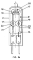
- FIG. 1 shows a halogen incandescent lamp 1 for general lighting purposes with a power of 200 W, which is preferably suitable for direct connection to the 110 V network. It has a cylindrical piston 2 made of quartz glass with an outer diameter of approximately 12.5 mm with an inner diameter of 10.5 mm (with a tolerance of 0.8 mm) and a total length of approximately 35 mm. One end of the piston 2 is shaped into a dome 3 which has a pump tip 4 in the center. The other end of the piston is closed with a pinch seal 5.
- the flask with a volume of 1.65 cm3 is filled with an inert gas mixture of 80% Kr and 20% N2, to which a halogen addition of 0.005% CBrClF2 is added.
- the luminous element 6 is mechanically held by a glass web 9 which bears against the inside of the rounded part 7.
- the web 9 is a glass tube which is formed from the material of the bulb and which extends transversely to the lamp axis and to the plane of the luminous element over the inside diameter of the bulb.
- the glass tube 9 has a diameter of approximately 1.2 mm near the axis and widens toward the piston wall 2 'on both sides in the manner of a funnel 10 to approximately twice (or even four times) the diameter.
- a plug 11 is left in the tube in the region of the lamp axis.
- the two luminous limbs 8 merge at their pinch-side ends into short, simply coiled sections which act as power supply lines 12.
- the luminous element 6 is tensioned in the bulb 2 in that the current leads 12 are melted into the pinch seal 5 and are welded there to sealing foils 13.
- the power supply lines 12 with a total length of approx. 6 mm protrude from the pinch seal 5 approx. 1 - 2 mm into the piston volume, which is why the usual core pins can advantageously be dispensed with.
- contact pins 14 are welded, which protrude beyond the end of the pinch seal 5 to the outside.
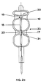
- FIG. 1 A second exemplary embodiment, the structure of which essentially corresponds to the first exemplary embodiment, is shown in FIG. It is a 220 V halogen incandescent lamp with a power of 100 W.
- the luminous element 15 is now bent in a U-shape.
- the two legs 8 'of the U which run parallel to the lamp axis, are in turn subdivided into two luminous, double-coiled sections 16, which are each connected to one another by a single-coiled section 17.
- the connecting part 18 of the U is also simply coiled. It is arranged transversely to the lamp axis in the vicinity of the pump tip 4, two short brackets 19 being angled through 90 ° and each extending to a section 16.
- the luminous element 15 is fixed by an oval glass web, the two halves of which are designed as longitudinal furrows 20. They extend over most of the length of the connecting part 18, so that it is squeezed between the two longitudinal furrows 20.
- the luminous element 15 is fixed in the region of the simply coiled sections 17 by a further glass web. It is a tube 21 with a circular cross-section which - like the oval tube - narrows increasingly like a funnel starting from the piston wall towards the center of the piston.
- a stopper 22 is left in the tube, into which the simply coiled section 17 is squeezed in the middle. This holding technique is particularly suitable as an alternative to the mechanical holder described in the first embodiment when using a single glass tube.
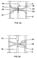
- FIG. 3a Another variant of this squeezing technique is shown in FIG. 3a.
- the glass web narrows to a tube 21 of constant diameter, the central stopper 22 of which squeezes the luminous element section 17.
- the plug has the shape of a solid cylinder.
- the helix of the connection section 17 can be short-circuited by a core pin 36.
- This technique is also particularly suitable for mechanically retaining webs, since effective cooling is particularly desirable here.
- FIG. 3b An alternative embodiment (FIG. 3b) uses a tube 24 which narrows from the bulb wall in a funnel shape towards the center of the lamp, the inner walls of which converge and thus form the plug region 25 into which the section 17 of the luminous element is squeezed.
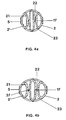
- FIG. 4a shows a schematic cross section through the lamp according to FIG. 2 at the level of the two funnel-shaped glass tubes 21, which fix the two sections 17 by being pinched.
- a flattened, e.g. oval or elliptical, cross section of the piston 2 ⁇ used (Fig. 4b).
- the volume of the piston 2 ⁇ need not change compared to a cylindrical piston 2.
- the semi-axis advantageously shortens in the direction of the glass webs, while the semi-axis extends transversely to the glass webs. In this way, a greater wall thickness of the glass tubes can be achieved compared to a cylindrical piston with the same volume.
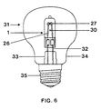
- FIG. 5 Another exemplary embodiment is finally shown in FIG. 5. It is a halogen incandescent lamp with an output of 50 W.
- the luminous element 26 is continuously coiled and bent in a U-shape.
- the fixation is carried out by two glass tubes 27. They squeeze the luminous element in the region of the two 90 ° bends between the legs 28 and the connecting part 29. However, the diameter of these webs is significantly larger (approx. Factor 1.4) than if a straight section of the filament was squeezed to fully enclose the 90 ° bend.
- the two glass tubes 27 can also be attached to the transverse connecting part 29 without including the 90 ° bends.
- the diameter of a glass web (or its height in the case of the furrow-like glass web) should be at least twice as large as the diameter of the lamp body area to be squeezed in order to ensure secure fixation.
- an additional separating web 30 is also arranged approximately centrally in the lamp bulb, so that it extends at the level of the center of the leg between the two legs 28 and transversely to them.
- the separating web prevents the two relatively long legs 28 from being knocked together.
- the use of a dividing web 30 (or more) is always advantageous if one wants to avoid direct fixation of the filament legs or also the provision of single or uncoiled filament portions in the area of the otherwise doubly coiled Thigh is undesirable.
- This separating web 30 is also designed as a funnel-shaped glass tube.
- Core pins 36 at the level of the separating web 30 are also suitable here for premature blackening or the like. to prevent.
- the halogen incandescent lamp of FIG. 5 described so far is mounted in an outer bulb 31 as an example.
- the possibly two-part power supply lines 32 are squeezed into a plate foot 33, which is melted into the neck 34 of the evacuated outer bulb 31.
- the outer bulb 31 carries a screw base 35.
- the invention is not restricted to the exemplary embodiments shown.
- the individual features of different exemplary embodiments can be combined with one another. It is particularly suitable the invention also for halogen incandescent lamps for mains operation at 110 V. Furthermore, the two legs of the filament can be subdivided again.
- the filling can also consist of other components known per se, for example CH2Br2 can be used as a halogen additive.
- Hard glass is also suitable as the bulb material, the luminous element being provided with external contact pins or the like via solid current leads known per se, which are melted directly into the pinch seal. connected is.
- the decision as to which type of glass webs is used in which number depends on the one hand on the temperature conditions and on the other hand on the free length of the lamp body sections and the shape of the lamp body. An indication of the free length is the voltage drop that occurs there. It should not exceed approx. 60 V.
- the number of glass webs varies in particular depending on the power level of the lamp and the length of the filament and its stability with regard to sagging. For stiff lamps with high performance may be sufficient already a glass walkway. Under certain circumstances, more than three glass webs can be used for less stiff lamps with low power.
- the invention provides an inexpensive halogen incandescent lamp with low power consumption down to 15 W for direct mains connection, as is of particular interest for general lighting.
Landscapes
- Non-Portable Lighting Devices Or Systems Thereof (AREA)
- Resistance Heating (AREA)
- Discharge Lamp (AREA)
- Vessels And Coating Films For Discharge Lamps (AREA)
- Glass Compositions (AREA)
- Lining Or Joining Of Plastics Or The Like (AREA)
- Encapsulation Of And Coatings For Semiconductor Or Solid State Devices (AREA)
- Led Devices (AREA)
- Securing Globes, Refractors, Reflectors Or The Like (AREA)
- Fastening Of Light Sources Or Lamp Holders (AREA)
Claims (14)
- Lampe à incandescence à halogène (1) à pincement d'un côté, destinée à fonctionner sur la tension du réseau, constituée de
une ampoule (2) fermée d'une manière hermétiquement étanche, en un matériau transparent et qui définit un axe longitudinal,
un remplissage formé d'un gaz inerte et d'un additif halogèné,
un corps lumineux (6;15;26) comportant au moins deux branches et une partie de liaison, notamment un corps lumineux en forme de V ou de U,
une barrette en verre (9), qui maintient le corps lumineux (6;15;26) dans la zone de la partie de liaison (7),
un système d'alimentation en courant, qui est relié aux deux extrémités des branches du corps lumineux,
caractérisée par le fait que le corps lumineux (6;15;26) est retenu exclusivement par une ou plusieurs barrettes (9;20;21; 27;30), qui sont formées par le matériau de l'ampoule et s'étendent essentiellement transversalement à l'axe longitudinal respectivement entre deux points approximativement opposés des parois latérales de l'ampoule. - Lampe à incandescence à halogène suivant la revendication 1, caractérisée par le fait que le corps lumineux (6;15;26) définit un plan, les barrettes (9;20;21;27,30) s'étendant transversalement à l'axe longitudinal et au plan du corps lumineux.
- Lampe à incandescence à halogène suivant la revendication 1, caractérisée par le fait qu'on utilise au moins une première barrette en verre (9), qui maintient le corps lumineux dans la zone de la partie de liaison (7).
- Lampe à incandescence à halogène suivant la revendication 3, caractérisée par le fait qu'au moins deux autres barrettes en verre (21) immobilisent le corps lumineux dans la zone des branches (8′).
- Lampe à incandescence à halogène suivant la revendication 1, caractérisée par le fait que le corps lumineux (15;26) est pincé au moins dans une partie des barrettes (20,21; 27).
- Lampe à incandescence à halogène suivant la revendication 1, caractérisée par le fait que le corps lumineux (6) est maintenu mécaniquement au moins par une partie des barrettes (9).
- Lampe à incandescence à halogène suivant la revendication 1, caractérisée par le fait que les barrettes (9;21;27,30) ont une forme tubulaire.
- Lampe à incandescence à halogène suivant la revendication 7, caractérisée par le fait que les barrettes s'élargissent en forme d'entonnoir en direction de la paroi de l'ampoule.
- Lampe à incandescence à halogène suivant la revendication 1, caractérisée par le fait que le corps lumineux (15) est subdivisé en plusieurs éléments lumineux (16), qui sont séparés par un ou plusieurs éléments de liaison (17), les éléments lumineux (16) étant enroulés en spirale double et le ou les éléments de liaison (17) étant enroulés en spirale simple ou n'étant pas enroulés en spirale.
- Lampe à incandescence à halogène suivant la revendication 9, caractérisée par le fait que les barrettes (21) maintiennent le corps lumineux (15) dans la zone des éléments de liaison (17).
- Lampe à incandescence à halogène suivant la revendication 3, caractérisée par le fait que le corps lumineux (15) est coudé en forme de U et que la barrette (20), qui maintient le corps lumineux (15) dans la zone de la partie de liaison (17) possède une section transversale ovale.
- Lampe à incandescence à halogène suivant la revendication 1, caractérisée par le fait que l'ampoule est un tube de section transversale circulaire ou aplatie et, dans ce dernier cas, les barrettes s'étendent parallèlement à l'axe transversal le plus court.
- Lampe à incandescence à halogène suivant la revendication 1, caractérisée par le fait que les éléments en spirale (17), qui sont voisins d'une barrette en verre (21;30) sont équipés d'une tige formant noyau (36) pour un meilleur refroidissement.
- Procédé de fabrication d'une lampe à halogène suivant la revendication 1, caractérisé par le fait qu'on forme chaque barrette en chauffant ponctuellement l'ampoule de la lampe, ouverte d'un côté, après l'introduction du corps lumineux, avec deux brûleurs situés à l'opposé l'un de l'autre et qu'on enfonce dans l'ampoule deux poinçons.
Applications Claiming Priority (2)
| Application Number | Priority Date | Filing Date | Title |
|---|---|---|---|
| DE4008367A DE4008367A1 (de) | 1990-03-15 | 1990-03-15 | Einseitig gequetschte halogengluehlampe |
| DE4008367 | 1990-03-15 |
Publications (3)
| Publication Number | Publication Date |
|---|---|
| EP0446460A2 EP0446460A2 (fr) | 1991-09-18 |
| EP0446460A3 EP0446460A3 (en) | 1992-02-26 |
| EP0446460B1 true EP0446460B1 (fr) | 1995-11-08 |
Family
ID=6402318
Family Applications (1)
| Application Number | Title | Priority Date | Filing Date |
|---|---|---|---|
| EP90124460A Expired - Lifetime EP0446460B1 (fr) | 1990-03-15 | 1990-12-17 | Lampe à incandescence à halogène munie d'un pincement unique |
Country Status (8)
| Country | Link |
|---|---|
| EP (1) | EP0446460B1 (fr) |
| JP (1) | JP2593589B2 (fr) |
| KR (1) | KR0156004B1 (fr) |
| AT (1) | ATE130123T1 (fr) |
| DE (2) | DE4008367A1 (fr) |
| ES (1) | ES2079426T3 (fr) |
| HK (1) | HK1000611A1 (fr) |
| HU (1) | HU207177B (fr) |
Cited By (1)
| Publication number | Priority date | Publication date | Assignee | Title |
|---|---|---|---|---|
| EP1670037A1 (fr) | 2004-09-10 | 2006-06-14 | Patent-Treuhand-Gesellschaft für elektrische Glühlampen mbH | Lampe à incandescence |
Families Citing this family (16)
| Publication number | Priority date | Publication date | Assignee | Title |
|---|---|---|---|---|
| US5565734A (en) * | 1993-03-19 | 1996-10-15 | U.S. Philips Corporation | Electric incandescent lamp having filament sleeves engaged by envelope constrictions supporting the filament |
| EP0802561B1 (fr) * | 1996-04-19 | 2000-07-19 | Patent-Treuhand-Gesellschaft für elektrische Glühlampen mbH | Lampe halogène |
| DE29612757U1 (de) * | 1996-07-24 | 1997-11-20 | Patent-Treuhand-Gesellschaft für elektrische Glühlampen mbH, 81543 München | Einseitig verschlossene elektrische Glühlampe |
| DE10236549A1 (de) * | 2002-08-08 | 2004-03-04 | Patent-Treuhand-Gesellschaft für elektrische Glühlampen mbH | Elektrische Glühlampe |
| DE102004028004A1 (de) * | 2004-06-09 | 2005-12-29 | Patent-Treuhand-Gesellschaft für elektrische Glühlampen mbH | Verfahren zur Bearbeitung einer Lampe und nach einem derartigen Verfahren bearbeitete Lampe |
| DE102004033117A1 (de) | 2004-07-08 | 2006-01-26 | Patent-Treuhand-Gesellschaft für elektrische Glühlampen mbH | Halogenglühlampe |
| DE102004060918A1 (de) | 2004-12-17 | 2006-06-22 | Patent-Treuhand-Gesellschaft für elektrische Glühlampen mbH | PAR-Lampenanordnung |
| DE102005019113A1 (de) | 2005-04-25 | 2006-10-26 | Patent-Treuhand-Gesellschaft für elektrische Glühlampen mbH | Halogenglühlampe und Verfahren zu ihrer Herstellung |
| DE102005019829A1 (de) * | 2005-04-28 | 2006-11-02 | Patent-Treuhand-Gesellschaft für elektrische Glühlampen mbH | Elektrische Lampe mit Halternoppen für den Leuchtkörper |
| DE102005045644A1 (de) * | 2005-09-23 | 2007-03-29 | Patent-Treuhand-Gesellschaft für elektrische Glühlampen mbH | Elektrische Lampe mit Haltenoppen für den Leuchtkörper |
| DE202006002562U1 (de) * | 2006-02-17 | 2006-04-27 | Patent-Treuhand-Gesellschaft für elektrische Glühlampen mbH | Elektrische Lampe mit Haltequetschung für den Leuchtkörper |
| DE202008009152U1 (de) | 2008-07-08 | 2008-09-11 | Osram Gesellschaft mit beschränkter Haftung | Halogenglühlampe |
| DE102008032167A1 (de) | 2008-07-08 | 2010-01-14 | Osram Gesellschaft mit beschränkter Haftung | Halogenglühlampe |
| DE102008054287A1 (de) * | 2008-11-03 | 2010-05-06 | Osram Gesellschaft mit beschränkter Haftung | Halogenglühlampe für den Betrieb an Netzspannung |
| DE102008061776A1 (de) | 2008-12-11 | 2010-06-17 | Osram Gesellschaft mit beschränkter Haftung | Halogenglühlampe |
| DE102008063622A1 (de) | 2008-12-18 | 2010-06-24 | Osram Gesellschaft mit beschränkter Haftung | Halogenglühlampe und zugehöriges optisches Bauteil |
Family Cites Families (3)
| Publication number | Priority date | Publication date | Assignee | Title |
|---|---|---|---|---|
| FR459316A (fr) * | 1913-04-04 | 1913-11-03 | Ehrich & Graetz Ag | Lampe à incandescence à fil enroulé |
| US3237045A (en) * | 1962-03-16 | 1966-02-22 | Gen Electric | Bent end electric lamp having lead wires anchored at ends of bend and provided with expansion portion |
| CA1245704A (fr) * | 1984-09-04 | 1988-11-29 | Arnold E. Westlund, Jr. | Lampe a halogene a support sans pont |
-
1990
- 1990-03-15 DE DE4008367A patent/DE4008367A1/de not_active Withdrawn
- 1990-12-17 ES ES90124460T patent/ES2079426T3/es not_active Expired - Lifetime
- 1990-12-17 DE DE59009860T patent/DE59009860D1/de not_active Expired - Lifetime
- 1990-12-17 AT AT90124460T patent/ATE130123T1/de not_active IP Right Cessation
- 1990-12-17 EP EP90124460A patent/EP0446460B1/fr not_active Expired - Lifetime
-
1991
- 1991-03-13 JP JP3048137A patent/JP2593589B2/ja not_active Expired - Lifetime
- 1991-03-14 HU HU91853A patent/HU207177B/hu unknown
- 1991-03-15 KR KR1019910004123A patent/KR0156004B1/ko not_active Expired - Lifetime
-
1997
- 1997-11-11 HK HK97102152A patent/HK1000611A1/xx not_active IP Right Cessation
Cited By (1)
| Publication number | Priority date | Publication date | Assignee | Title |
|---|---|---|---|---|
| EP1670037A1 (fr) | 2004-09-10 | 2006-06-14 | Patent-Treuhand-Gesellschaft für elektrische Glühlampen mbH | Lampe à incandescence |
Also Published As
| Publication number | Publication date |
|---|---|
| JPH04220943A (ja) | 1992-08-11 |
| ES2079426T3 (es) | 1996-01-16 |
| KR0156004B1 (ko) | 1998-11-16 |
| EP0446460A2 (fr) | 1991-09-18 |
| HU910853D0 (en) | 1991-09-30 |
| DE4008367A1 (de) | 1991-09-26 |
| HU207177B (en) | 1993-03-01 |
| JP2593589B2 (ja) | 1997-03-26 |
| HUT57474A (en) | 1991-11-28 |
| ATE130123T1 (de) | 1995-11-15 |
| EP0446460A3 (en) | 1992-02-26 |
| HK1000611A1 (en) | 1998-04-09 |
| DE59009860D1 (de) | 1995-12-14 |
Similar Documents
| Publication | Publication Date | Title |
|---|---|---|
| EP0446460B1 (fr) | Lampe à incandescence à halogène munie d'un pincement unique | |
| EP0451647B1 (fr) | Lampe à décharge à haute pression et son procédé de fabrication | |
| DE10163584C1 (de) | Verfahren und Vorrichtung zur Herstellung von Lampenkolben mit nicht-rotationssymmetrischer und/oder konkaver innerer und/oder äußerer Form | |
| EP0239006B1 (fr) | Lampe à incandescence à halogène et son procédé de fabrication | |
| DE69405181T2 (de) | Hochdruck-Entladungslampe | |
| EP0446458B1 (fr) | Lampe à incandescence à halogène à double pincement | |
| DE69011145T2 (de) | Einseitig gequetschte Metalldampfentladungslampe. | |
| EP0479088A1 (fr) | Lampe à décharge à haute pression et procédé de fabrication | |
| DD156209A1 (de) | Elektrische entladungslampe mit keramikentladungsrohr | |
| EP0446459B1 (fr) | Lampe à incandescence à halogène munie d'un pincement unique | |
| EP0446461B1 (fr) | Lampe à incandescence à halogène munie d'un pincement unique | |
| DE4008334A1 (de) | Einseitig gequetschte halogengluehlampe | |
| DE102008054287A1 (de) | Halogenglühlampe für den Betrieb an Netzspannung | |
| DE69510883T2 (de) | Hochdruckentladungslampe | |
| EP0219860B1 (fr) | Méthode de fabrication d'une lampe à décharge à haute pression à halogénures de métal à pincement unique et une lampe fabriquée suivant cette méthode | |
| DE1054575B (de) | Einschmelzung und Halterung fuer Hochdruckentladungslampen | |
| DE112008001624T5 (de) | Hochintensitätsentladungslampe mit verbesserten Dimmeigenschaften | |
| DE2909259A1 (de) | Wolfram-halogen-lampe fuer einen monoblock-scheinwerfer sowie methode zu ihrer herstellung | |
| DE2420342A1 (de) | Halogengluehlampe und verfahren zur herstellung | |
| DE69501355T2 (de) | Glühwendellampe | |
| DE10214777A1 (de) | Metallhalogenidlampe mit keramischem Entladungsgefäß | |
| DE2814823A1 (de) | Elektrische gluehlampe | |
| DE9102566U1 (de) | Halogenglühlampe | |
| AT398864B (de) | Halogenglühlampe | |
| DE1764352A1 (de) | Elektrische Lampe |
Legal Events
| Date | Code | Title | Description |
|---|---|---|---|
| PUAI | Public reference made under article 153(3) epc to a published international application that has entered the european phase |
Free format text: ORIGINAL CODE: 0009012 |
|
| 17P | Request for examination filed |
Effective date: 19901217 |
|
| AK | Designated contracting states |
Kind code of ref document: A2 Designated state(s): AT BE CH DE ES FR GB IT LI |
|
| PUAL | Search report despatched |
Free format text: ORIGINAL CODE: 0009013 |
|
| AK | Designated contracting states |
Kind code of ref document: A3 Designated state(s): AT BE CH DE ES FR GB IT LI |
|
| 17Q | First examination report despatched |
Effective date: 19940822 |
|
| GRAA | (expected) grant |
Free format text: ORIGINAL CODE: 0009210 |
|
| AK | Designated contracting states |
Kind code of ref document: B1 Designated state(s): AT BE CH DE ES FR GB IT LI |
|
| REF | Corresponds to: |
Ref document number: 130123 Country of ref document: AT Date of ref document: 19951115 Kind code of ref document: T |
|
| REF | Corresponds to: |
Ref document number: 59009860 Country of ref document: DE Date of ref document: 19951214 |
|
| REG | Reference to a national code |
Ref country code: ES Ref legal event code: FG2A Ref document number: 2079426 Country of ref document: ES Kind code of ref document: T3 |
|
| ITF | It: translation for a ep patent filed | ||
| REG | Reference to a national code |
Ref country code: CH Ref legal event code: NV Representative=s name: SIEMENS-ALBIS AKTIENGESELLSCHAFT |
|
| GBT | Gb: translation of ep patent filed (gb section 77(6)(a)/1977) |
Effective date: 19960122 |
|
| ET | Fr: translation filed | ||
| PLBE | No opposition filed within time limit |
Free format text: ORIGINAL CODE: 0009261 |
|
| STAA | Information on the status of an ep patent application or granted ep patent |
Free format text: STATUS: NO OPPOSITION FILED WITHIN TIME LIMIT |
|
| 26N | No opposition filed | ||
| REG | Reference to a national code |
Ref country code: GB Ref legal event code: IF02 |
|
| PGFP | Annual fee paid to national office [announced via postgrant information from national office to epo] |
Ref country code: IT Payment date: 20061231 Year of fee payment: 17 |
|
| PGFP | Annual fee paid to national office [announced via postgrant information from national office to epo] |
Ref country code: CH Payment date: 20080304 Year of fee payment: 18 |
|
| PGFP | Annual fee paid to national office [announced via postgrant information from national office to epo] |
Ref country code: AT Payment date: 20081107 Year of fee payment: 19 |
|
| REG | Reference to a national code |
Ref country code: CH Ref legal event code: PFA Owner name: PATENT-TREUHAND-GESELLSCHAFT FUER ELEKTRISCHE GLU Free format text: PATENT-TREUHAND-GESELLSCHAFT FUER ELEKTRISCHE GLUEHLAMPEN MBH#HELLABRUNNER STRASSE 1#D-81543 MUENCHEN (DE) -TRANSFER TO- PATENT-TREUHAND-GESELLSCHAFT FUER ELEKTRISCHE GLUEHLAMPEN MBH#HELLABRUNNER STRASSE 1#D-81543 MUENCHEN (DE) |
|
| PGFP | Annual fee paid to national office [announced via postgrant information from national office to epo] |
Ref country code: ES Payment date: 20090114 Year of fee payment: 19 |
|
| REG | Reference to a national code |
Ref country code: CH Ref legal event code: PL |
|
| PG25 | Lapsed in a contracting state [announced via postgrant information from national office to epo] |
Ref country code: IT Free format text: LAPSE BECAUSE OF NON-PAYMENT OF DUE FEES Effective date: 20071217 |
|
| PG25 | Lapsed in a contracting state [announced via postgrant information from national office to epo] |
Ref country code: LI Free format text: LAPSE BECAUSE OF NON-PAYMENT OF DUE FEES Effective date: 20081231 Ref country code: CH Free format text: LAPSE BECAUSE OF NON-PAYMENT OF DUE FEES Effective date: 20081231 |
|
| PGFP | Annual fee paid to national office [announced via postgrant information from national office to epo] |
Ref country code: GB Payment date: 20091210 Year of fee payment: 20 |
|
| PGFP | Annual fee paid to national office [announced via postgrant information from national office to epo] |
Ref country code: BE Payment date: 20091216 Year of fee payment: 20 Ref country code: DE Payment date: 20100219 Year of fee payment: 20 |
|
| PGFP | Annual fee paid to national office [announced via postgrant information from national office to epo] |
Ref country code: FR Payment date: 20100423 Year of fee payment: 20 |
|
| PG25 | Lapsed in a contracting state [announced via postgrant information from national office to epo] |
Ref country code: AT Free format text: LAPSE BECAUSE OF NON-PAYMENT OF DUE FEES Effective date: 20091217 |
|
| BE20 | Be: patent expired |
Owner name: *PATENT-TREUHAND-GESELLSCHAFT FUR ELEKTRISCHE GLUH Effective date: 20101217 |
|
| REG | Reference to a national code |
Ref country code: GB Ref legal event code: PE20 Expiry date: 20101216 |
|
| REG | Reference to a national code |
Ref country code: ES Ref legal event code: FD2A Effective date: 20110225 |
|
| PG25 | Lapsed in a contracting state [announced via postgrant information from national office to epo] |
Ref country code: GB Free format text: LAPSE BECAUSE OF EXPIRATION OF PROTECTION Effective date: 20101216 |
|
| PG25 | Lapsed in a contracting state [announced via postgrant information from national office to epo] |
Ref country code: ES Free format text: LAPSE BECAUSE OF EXPIRATION OF PROTECTION Effective date: 20101218 |
|
| PG25 | Lapsed in a contracting state [announced via postgrant information from national office to epo] |
Ref country code: DE Free format text: LAPSE BECAUSE OF EXPIRATION OF PROTECTION Effective date: 20101217 |
|
| PG25 | Lapsed in a contracting state [announced via postgrant information from national office to epo] |
Ref country code: ES Free format text: LAPSE BECAUSE OF EXPIRATION OF PROTECTION Effective date: 20091218 |