EP0446491A1 - Réservoir actionné pneumatiquement pour appareil respiratoire à circuit fermé sous surpression - Google Patents
Réservoir actionné pneumatiquement pour appareil respiratoire à circuit fermé sous surpression Download PDFInfo
- Publication number
- EP0446491A1 EP0446491A1 EP90200584A EP90200584A EP0446491A1 EP 0446491 A1 EP0446491 A1 EP 0446491A1 EP 90200584 A EP90200584 A EP 90200584A EP 90200584 A EP90200584 A EP 90200584A EP 0446491 A1 EP0446491 A1 EP 0446491A1
- Authority
- EP
- European Patent Office
- Prior art keywords
- breathing
- chamber
- conduit
- pressure
- storage chamber
- Prior art date
- Legal status (The legal status is an assumption and is not a legal conclusion. Google has not performed a legal analysis and makes no representation as to the accuracy of the status listed.)
- Withdrawn
Links
- 230000029058 respiratory gaseous exchange Effects 0.000 title claims abstract description 72
- 239000012530 fluid Substances 0.000 claims description 24
- CURLTUGMZLYLDI-UHFFFAOYSA-N Carbon dioxide Chemical compound O=C=O CURLTUGMZLYLDI-UHFFFAOYSA-N 0.000 claims description 8
- 229910002092 carbon dioxide Inorganic materials 0.000 claims description 4
- 239000001569 carbon dioxide Substances 0.000 claims description 4
- XLYOFNOQVPJJNP-UHFFFAOYSA-N water Substances O XLYOFNOQVPJJNP-UHFFFAOYSA-N 0.000 claims description 3
- 239000012528 membrane Substances 0.000 claims description 2
- 210000002345 respiratory system Anatomy 0.000 claims 1
- QVGXLLKOCUKJST-UHFFFAOYSA-N atomic oxygen Chemical compound [O] QVGXLLKOCUKJST-UHFFFAOYSA-N 0.000 abstract description 11
- 229910052760 oxygen Inorganic materials 0.000 abstract description 11
- 239000001301 oxygen Substances 0.000 abstract description 11
- 239000007789 gas Substances 0.000 abstract description 8
- 230000007246 mechanism Effects 0.000 abstract description 2
- 239000000126 substance Substances 0.000 description 5
- 230000004044 response Effects 0.000 description 4
- 239000000463 material Substances 0.000 description 3
- 230000007935 neutral effect Effects 0.000 description 3
- OKTJSMMVPCPJKN-UHFFFAOYSA-N Carbon Chemical compound [C] OKTJSMMVPCPJKN-UHFFFAOYSA-N 0.000 description 2
- 230000008901 benefit Effects 0.000 description 2
- 229910052799 carbon Inorganic materials 0.000 description 2
- 239000003638 chemical reducing agent Substances 0.000 description 2
- 230000002503 metabolic effect Effects 0.000 description 2
- XXQBEVHPUKOQEO-UHFFFAOYSA-N potassium superoxide Chemical compound [K+].[K+].[O-][O-] XXQBEVHPUKOQEO-UHFFFAOYSA-N 0.000 description 2
- 230000003068 static effect Effects 0.000 description 2
- WHXSMMKQMYFTQS-UHFFFAOYSA-N Lithium Chemical compound [Li] WHXSMMKQMYFTQS-UHFFFAOYSA-N 0.000 description 1
- 230000006978 adaptation Effects 0.000 description 1
- 239000003570 air Substances 0.000 description 1
- 230000000712 assembly Effects 0.000 description 1
- 238000000429 assembly Methods 0.000 description 1
- 230000008859 change Effects 0.000 description 1
- 238000010586 diagram Methods 0.000 description 1
- 238000006073 displacement reaction Methods 0.000 description 1
- 229910052744 lithium Inorganic materials 0.000 description 1
- 239000000203 mixture Substances 0.000 description 1
- 238000012986 modification Methods 0.000 description 1
- 230000004048 modification Effects 0.000 description 1
- 230000001473 noxious effect Effects 0.000 description 1
- 230000002265 prevention Effects 0.000 description 1
- 230000001105 regulatory effect Effects 0.000 description 1
- 230000000241 respiratory effect Effects 0.000 description 1
- 238000007789 sealing Methods 0.000 description 1
Images
Classifications
-
- A—HUMAN NECESSITIES
- A62—LIFE-SAVING; FIRE-FIGHTING
- A62B—DEVICES, APPARATUS OR METHODS FOR LIFE-SAVING
- A62B7/00—Respiratory apparatus
- A62B7/10—Respiratory apparatus with filter elements
Definitions
- This invention relates to a self-contained breathing apparatus, and more particularly to a closed-circuit positive pressure self-contained breathing apparatus for temporary use by a wearer in a noxious environment, such as is worn by a firefighter.
- SCBA Self-contained breathing apparatus
- NFPA National Fire Prevention Administration
- SCBA's Self-contained breathing apparatus
- SCBA's are classified as open-circuit (where the user's exhalation is dumped from the system) or closed-circuit (where exhalation is returned to the system for subsequent reuse after carbon dioxide is removed and oxygen is added).
- closed-circuit self-contained breathing apparatus have existed longer than open-circuit types, there are some inherent disadvantages of closed-circuit systems which offset the substantial weight and size advantage they offer for extended duration.
- One disadvantage is the sluggish response of the system to the user's breathing requirements, particularly at high metabolic work rates.
- a second disadvantage is the design difficulty encountered in trying to create a constant positive pressure in the facepiece (positive pressure substantially increases the degree of respiratory protection to the wearer).
- An object of the present invention is to provide an improved self-contained closed-circuit positive pressure breathing apparatus of extended rating which provides an amplified response to the user's breathing effort, resulting in very low breathing resistance.
- Another object of the present invention is to provide an improved closed-circuit self-contained breathing apparatus which is capable of maintaining a positive pressure in the facepiece, even during high inhalation flow rates, but without having substantial resistance to high exhalation flows.
- Still another object of the present invention is to provide an improved close-circuit positive pressure self-contained breathing apparatus with breathing performance which meets or exceeds that of an open-circuit apparatus.
- Yet another object of the present invention is to provide an improved closed-circuit self-contained positive pressure breathing apparatus.
- a self-contained breathing apparatus of the positive pressure type wherein there is provided a pneumatic servo mechanism responsive to a pressure sensor to drive a breathing storage chamber by expansion of an oxygen containing gas from a storage tank therefor.
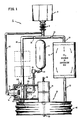
- FIG. 1 there is schematically illustrated a self-contained breathing apparatus of the present invention, generally indicated as 10, mounted in a supporting carrier assembly (not shown) including a helmet (H) and comprised of a compressed breathing gas supply tank 12; a pneumatic servovalve assembly, generally indicated as 14; an inhale/exhale delivery conduit 16; a canister assembly 18 and a breathing storage assembly 20.
- the breathing gas supply tank 12 (containing either air, oxygen, oxygen enriched air, or another mixture of oxygen in combination with other breathable gases) is of a size to provide about 2 to 5 liters of air to the system, depending on the user's metabolic work rate and is connected by a conduit 22 under the control of a pressure reducer valve 24 via a conduit 26 to the pneumatic servovalve assembly 14.
- the inhale/exhale delivery conduit 16 is connected by a conduit 28 under the control of one-way valve 30 to the chemical canister assembly 18 for the removal of carbon dioxide (and possibly chemical addition of oxygen) therein as known to one skilled in the art.
- the canister assembly 18 is connected by a conduit 32 to the breathing storage assembly 20 defining a variable volume gaseous storage chamber 34 in fluid communication by a conduit 36 under the control of one-way valve 38 with the inhale-exhale delivery conduit 16.
- a conduit 40 is provided between the pneumatic servovalve assembly 14 and the inhale/exhale delivery conduit 16 to sense the breathing circuit pressure therein.
- the cannister assembly 18 contains a chemical bed (or beds) of one or more well known carbon dioxide-adsorbing material, and possibly one or more oxygen producing chemicals.
- Various carbon dioxide-adsorbing materials are well known and readily available at relatively inexpensive prices.
- the material producing oxygen could be one of several known chemicals which react with moisture and carbon dioxide to generate oxygen, such as potassium superoxide, lithium superperborate or the like.
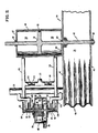
- the breathing storage assembly 20 is comprised of an upper wall 42 and a lower wall 44 connected by flexible bellowed-shaped side wall 46 and reinforced to withstand significant positive and negative internal pressure.
- a rod member 48 vertically disposed for reciprocal movement and mounted by a nut 50 to the lower wall 44 of the breathing storage assembly 20.
- the rod member 48 is provided with a piston 52 disposed in a cylinder member 54 mounted to an upper surface portion of the upper wall 42 of the breathing storage chamber 34 and defining an upper chamber 56 and a lower chamber 58 therein.
- the cylinder member 54 is preferably mounted to the upper wall 42 of the breathing storage assembly 20 to ensure positive displacement of the rod member 48 mounted to the lower wall member 44 with respect to the movement of the rod member 48 and associated piston 52 disposed within the cylinder member 54 as more fully hereinafter described.
- the rod member 48 is provided with appropriate sealing assemblies, such as ring members 60 disposed in upper and lower walls 62 and 64 of the cylinder member 54.
- the piston 52 is provided with a ring seal 66 to prevent fluid flow between the upper and lower chamber 56 and 58 of the cylinder member 54.
- the pneumatic servovalve assembly 14 includes a cylindrically-shaped pressure sensor housing 70 defining a chamber 72 and having a diaphragm member, generally indicated as 74, including a disc-shaped body portion 76 and a spindle member 78 positioned within the chamber 72 and defining an upper chamber 80 and a lower chamber 82 with a donut-shaped flexible membrane member 84 attached between the body portion 76 and the pressure sensor housing 70.
- the upper portion of the pressure sensor housing 70 is provided with channels 86 to provide fluid communication between the atmosphere and the upper chamber 72 of the pressure sensor housing 70.
- a channel 88 is provided in the lower portion of the pressure sensor housing 70 to provide fluid communication between the lower chamber 82 and the conduit 40 as more fully hereinafter described.
- the spindle member 78 is provided with an upper valve portion 92 and a lower valve portion 94 for positioning within valve seating chambers 96 and 98, respectively, formed in the upper and lower wall portions of the pressure sensor housing 70.
- Diaphragn seals 100 and 102 are mounted to the upper and lower portions of the spindle member 78 and to proximate portions of the pressure sensor housing 70 to isolate the chambers 80 and 82 from the valve seating chambers 96 and 98.
- the upper valve seating chamber 96 is in fluid communication via an orifice 104 with the chamber 56 of the member 54 by a conduit member 105 and with the conduit 36 via a conduit 106.
- the lower valve seating chamber 98 is in fluid communication via an orifice 108 with the chamber 58 of the cylinder member 54 via a conduit member 110 and with the conduit 36 via a conduit 112.
- a positive pressure of approximately 20 mm. of water in the breathing conduit 16 is transmitted to the chamber 82 via the conduit 40 so that the spindle member 78 is lifted to a neutral position with equal flow restriction through orifices 104 and 108.
- An intermediate conduit 114 including reducing orifices 116 and 118 is provided for fluid communication between the conduit member 105 and the conduit member 110 and the conduit 26 to provide fluid communication of the compressed air from the pressure reducer 24 to the pneumatic servovalve assembly 14.
- a coil spring 118 is provided in the upper chamber of the pressure sensor housing 70 to bias the valve portion 94 of the spindle member 78 against the needle valve chamber 98 in order to create a positive pressure in the breathing circuit.
- a positive pressure of approximately 20 mm. of water in the breathing conduit 16 is transmitted to the chamber 82 via the conduit 40 so that the spindle member 78 is lifted to a neutral position with equal flow restriction through orifices 104 and 108.
- the spindle member 78 acts as a rod stem at each end by restricting flow through either the upper orifice 104 or the lower orifice 108 thereby creating an imbalance in the pneumatic network comprised by the pneumatic resistance of the orifices 104, 108, 116 and 118.
- the chambers 56 and 58 of the cylinder member 54 function to control the movement of the piston 52 (and thus the movement of the breathing storage chamber 20) as a result of the pressure imbalance between the chambers 56 and 58.
- the pressure on the breathing circuit in conduit 16 drops slightly below the 20 mm. static pressure, causing the pressure in the lower chamber 58 of the cylinder 54 to increase thereby applying a net upward force against the piston 52 of the rod member 48 to cause the lower wall 44 to rise and compress the breathing storage chamber 34 with sufficient force to overcome what ever resistance is present between the storage chamber 34 and the helmet (H).
- pressure in the breathing circuit increases towards the 20 mm. static pressure thereby providing feed-back to the pneumatic servovalve assembly 14 thereby returning to a neutral position the spindle member 78 of the pressure sensor housing 70.
- exhalation causes an increase in breathing circuit pressure in conduit 16 which causes an increase in pressure in the upper chamber 56 of the cylinder member 54 causing the breathing storage chamber 34 to expand to assist overcoming resistance in the exhalation circuitry.
- the energy in the pressurized breathing gas tank 12 to drive a servo assembly in response to the user's demand, energy otherwise unused, and without requiring substantially more gas than would be required to replenish oxygen or flush the rebreather system.
- the breathing gas is vented into the breathing circuit conduit 36 via conduits 106 and 112.
- the user's breathing creates a pressure change in the breathing conduit 16 which is transmitted through the conduit 40 to the lower chamber 82 of the pneumatic servovalve assembly 14 causing the spindle member 78 to respond up or down to restrict flow through either of the restrictive orifices 104 or 108, respectively.
Landscapes
- Health & Medical Sciences (AREA)
- Pulmonology (AREA)
- General Health & Medical Sciences (AREA)
- Business, Economics & Management (AREA)
- Emergency Management (AREA)
- Respiratory Apparatuses And Protective Means (AREA)
Applications Claiming Priority (1)
| Application Number | Priority Date | Filing Date | Title |
|---|---|---|---|
| US07/253,710 US4928685A (en) | 1988-10-05 | 1988-10-05 | Closed-circuit positive pressure breathing apparatus with pneumatically operated storage chamber |
Publications (1)
| Publication Number | Publication Date |
|---|---|
| EP0446491A1 true EP0446491A1 (fr) | 1991-09-18 |
Family
ID=22961404
Family Applications (1)
| Application Number | Title | Priority Date | Filing Date |
|---|---|---|---|
| EP90200584A Withdrawn EP0446491A1 (fr) | 1988-10-05 | 1990-03-12 | Réservoir actionné pneumatiquement pour appareil respiratoire à circuit fermé sous surpression |
Country Status (3)
| Country | Link |
|---|---|
| US (1) | US4928685A (fr) |
| EP (1) | EP0446491A1 (fr) |
| AU (1) | AU618663B2 (fr) |
Cited By (1)
| Publication number | Priority date | Publication date | Assignee | Title |
|---|---|---|---|---|
| EP1106500A3 (fr) * | 1999-12-07 | 2002-08-14 | Edward Cumming | Appareil respiratoire |
Families Citing this family (11)
| Publication number | Priority date | Publication date | Assignee | Title |
|---|---|---|---|---|
| DE3823382C1 (fr) * | 1988-07-09 | 1990-01-11 | Draegerwerk Ag, 2400 Luebeck, De | |
| US5000174A (en) * | 1989-10-03 | 1991-03-19 | Cairns & Brother Inc. | Positive pressure breathing assembly and demand regulator therefor |
| DE3938889A1 (de) * | 1989-11-24 | 1991-05-29 | Messer Griesheim Gmbh | Temperierbare behandlungskammer zur durchfuehrung therapeutischer verfahren |
| DE4416599C2 (de) * | 1994-05-11 | 1997-03-20 | Delta Barth Systemhaus Gmbh | Beatmungsgerät |
| US7596965B2 (en) * | 2005-05-13 | 2009-10-06 | Anesthetic Gas Reclamation, Llc | Anesthetic gas reclamation system and method |
| US7669438B2 (en) * | 2005-05-13 | 2010-03-02 | Anesthetic Gas Reclamation, Llc | Method and apparatus for anesthetic gas reclamation with compression stage |
| US7628034B2 (en) * | 2005-05-13 | 2009-12-08 | Anesthetic Gas Reclamation, Llc | Method of low flow anesthetic gas scavenging and dynamic collection apparatus therefor |
| US8267081B2 (en) | 2009-02-20 | 2012-09-18 | Baxter International Inc. | Inhaled anesthetic agent therapy and delivery system |
| US10413642B2 (en) | 2015-04-28 | 2019-09-17 | James Michael Berry | System for dynamic control of medical vacuum |
| CN111420313A (zh) * | 2020-05-15 | 2020-07-17 | 上海孚邦实业有限公司 | 一种闭路式呼吸器 |
| PL447496A1 (pl) * | 2024-01-12 | 2025-02-03 | Xdeep Spółka Z Ograniczoną Odpowiedzialnością Spółka Komandytowa | Kompaktowy kanister złoża pochłaniacza dwutlenku węgla (skrubera) |
Citations (2)
| Publication number | Priority date | Publication date | Assignee | Title |
|---|---|---|---|---|
| FR2587297A1 (fr) * | 1985-09-18 | 1987-03-20 | Ottestad Nils | Systeme de respiration pour scaphandrier |
| FR2622459A1 (fr) * | 1987-11-03 | 1989-05-05 | Draegerwerk Ag | Appareil respiratoire a circuit ferme |
Family Cites Families (11)
| Publication number | Priority date | Publication date | Assignee | Title |
|---|---|---|---|---|
| US3058460A (en) * | 1957-01-08 | 1962-10-16 | Stephenson Corp | Method and apparatus for supplying and exhausting or exchanging a controlled volume of gas |
| USRE25871E (en) * | 1958-12-05 | 1965-10-05 | Lung ventilators and control mechanism therefor | |
| US3126001A (en) * | 1959-09-16 | 1964-03-24 | Arrangement in respirators | |
| GB1062772A (en) * | 1963-03-20 | 1967-03-22 | Geoffrey Barnett Burchell | A respiratory apparatus |
| US3251359A (en) * | 1963-04-25 | 1966-05-17 | Ismach Aaron | Automatic intermittent positive pressure ventilators |
| GB1248302A (en) * | 1969-01-30 | 1971-09-29 | Pye Ltd | Improvements in or relating to closed circuit medical respirators |
| DE2430839C2 (de) * | 1974-06-27 | 1982-05-19 | Drägerwerk AG, 2400 Lübeck | Pneumatischer Oszillator für ein Beatmungsgerät |
| US4007736A (en) * | 1975-03-12 | 1977-02-15 | N.A.D., Inc. | Fluidic controlled ventilator |
| DE3015759C2 (de) * | 1980-04-24 | 1982-08-12 | Drägerwerk AG, 2400 Lübeck | Druckgas-Atemschutzgerät mit Überdruck in der Atemluft |
| ZA887338B (en) * | 1987-11-03 | 1989-06-28 | Draegerwerk Ag | Circulatory respiratory protective apparatus |
| DE3901919A1 (de) * | 1989-01-24 | 1990-07-26 | Draegerwerk Ag | Kreislaufatemschutzgeraet |
-
1988
- 1988-10-05 US US07/253,710 patent/US4928685A/en not_active Expired - Fee Related
-
1990
- 1990-03-12 EP EP90200584A patent/EP0446491A1/fr not_active Withdrawn
- 1990-03-19 AU AU51487/90A patent/AU618663B2/en not_active Ceased
Patent Citations (2)
| Publication number | Priority date | Publication date | Assignee | Title |
|---|---|---|---|---|
| FR2587297A1 (fr) * | 1985-09-18 | 1987-03-20 | Ottestad Nils | Systeme de respiration pour scaphandrier |
| FR2622459A1 (fr) * | 1987-11-03 | 1989-05-05 | Draegerwerk Ag | Appareil respiratoire a circuit ferme |
Cited By (2)
| Publication number | Priority date | Publication date | Assignee | Title |
|---|---|---|---|---|
| EP1106500A3 (fr) * | 1999-12-07 | 2002-08-14 | Edward Cumming | Appareil respiratoire |
| GB2357979B (en) * | 1999-12-07 | 2004-02-18 | Edward Cumming | Breathing apparatus |
Also Published As
| Publication number | Publication date |
|---|---|
| US4928685A (en) | 1990-05-29 |
| AU618663B2 (en) | 1992-01-02 |
| AU5148790A (en) | 1991-10-03 |
Similar Documents
| Publication | Publication Date | Title |
|---|---|---|
| US3805780A (en) | Mine rescue breathing apparatus | |
| US4440163A (en) | Emergency escape breathing apparatus | |
| US4964405A (en) | Emergency respiration apparatus | |
| US4879996A (en) | Closed circuit breathing apparatus | |
| US4409978A (en) | Portable, self-contained breathing apparatus | |
| US5036841A (en) | Self contained closed circuit breathing apparatus | |
| US4928685A (en) | Closed-circuit positive pressure breathing apparatus with pneumatically operated storage chamber | |
| CA1322710C (fr) | Appareil respiratoire | |
| CA1048889A (fr) | Raccord pour appareil respiratoire | |
| US20040089302A1 (en) | Breathing apparatus | |
| US6526971B2 (en) | Variable volume ratio compound counterlung | |
| CN101516722A (zh) | 压力激活装置和呼吸系统 | |
| JP2510678B2 (ja) | 閉ル―プ呼吸装置 | |
| US5074298A (en) | Gas flow control system | |
| US7628152B2 (en) | Breathing regulator with nonlinear positive pressure spring | |
| US3973562A (en) | Multi-user extended operation respirator | |
| US5787883A (en) | Spring-free pressure regulator with structure isolating exhaled air from valve | |
| CN215995334U (zh) | 一种适合消防员使用的高效呼吸器 | |
| US5619987A (en) | Semi-closed rebreathing apparatus with water removing pump | |
| US3794021A (en) | Dual mode mixed gas breathing apparatus | |
| CA2026239A1 (fr) | Respirateur a pression positive et regulateur a demande | |
| CA2011955A1 (fr) | Respirateur a pression positive en circuit ferme avec reservoir a commande pneumatique | |
| WO2005000409A1 (fr) | Ensemble regulateur de pression | |
| GB2191950A (en) | Emergency escape breathing apparatus | |
| AU684043B2 (en) | Semi-closed rebreathing apparatus |
Legal Events
| Date | Code | Title | Description |
|---|---|---|---|
| PUAI | Public reference made under article 153(3) epc to a published international application that has entered the european phase |
Free format text: ORIGINAL CODE: 0009012 |
|
| AK | Designated contracting states |
Kind code of ref document: A1 Designated state(s): AT BE CH DE ES FR GB IT LI LU NL SE |
|
| 17P | Request for examination filed |
Effective date: 19920311 |
|
| 17Q | First examination report despatched |
Effective date: 19930716 |
|
| STAA | Information on the status of an ep patent application or granted ep patent |
Free format text: STATUS: THE APPLICATION IS DEEMED TO BE WITHDRAWN |
|
| 18D | Application deemed to be withdrawn |
Effective date: 19940420 |