EP0446515A2 - Dynamic microphone and method of making the same - Google Patents
Dynamic microphone and method of making the same Download PDFInfo
- Publication number
- EP0446515A2 EP0446515A2 EP90304814A EP90304814A EP0446515A2 EP 0446515 A2 EP0446515 A2 EP 0446515A2 EP 90304814 A EP90304814 A EP 90304814A EP 90304814 A EP90304814 A EP 90304814A EP 0446515 A2 EP0446515 A2 EP 0446515A2
- Authority
- EP
- European Patent Office
- Prior art keywords
- voice coil
- diaphragm
- magnet
- diameter
- central portion
- Prior art date
- Legal status (The legal status is an assumption and is not a legal conclusion. Google has not performed a legal analysis and makes no representation as to the accuracy of the status listed.)
- Granted
Links
Images
Classifications
-
- H—ELECTRICITY
- H04—ELECTRIC COMMUNICATION TECHNIQUE
- H04R—LOUDSPEAKERS, MICROPHONES, GRAMOPHONE PICK-UPS OR LIKE ACOUSTIC ELECTROMECHANICAL TRANSDUCERS; ELECTRIC HEARING AIDS; PUBLIC ADDRESS SYSTEMS
- H04R7/00—Diaphragms for electromechanical transducers; Cones
- H04R7/02—Diaphragms for electromechanical transducers; Cones characterised by the construction
- H04R7/04—Plane diaphragms
- H04R7/06—Plane diaphragms comprising a plurality of sections or layers
- H04R7/10—Plane diaphragms comprising a plurality of sections or layers comprising superposed layers in contact
-
- H—ELECTRICITY
- H04—ELECTRIC COMMUNICATION TECHNIQUE
- H04R—LOUDSPEAKERS, MICROPHONES, GRAMOPHONE PICK-UPS OR LIKE ACOUSTIC ELECTROMECHANICAL TRANSDUCERS; ELECTRIC HEARING AIDS; PUBLIC ADDRESS SYSTEMS
- H04R31/00—Apparatus or processes specially adapted for the manufacture of transducers or diaphragms therefor
- H04R31/003—Apparatus or processes specially adapted for the manufacture of transducers or diaphragms therefor for diaphragms or their outer suspension
-
- H—ELECTRICITY
- H04—ELECTRIC COMMUNICATION TECHNIQUE
- H04R—LOUDSPEAKERS, MICROPHONES, GRAMOPHONE PICK-UPS OR LIKE ACOUSTIC ELECTROMECHANICAL TRANSDUCERS; ELECTRIC HEARING AIDS; PUBLIC ADDRESS SYSTEMS
- H04R31/00—Apparatus or processes specially adapted for the manufacture of transducers or diaphragms therefor
- H04R31/006—Interconnection of transducer parts
-
- H—ELECTRICITY
- H04—ELECTRIC COMMUNICATION TECHNIQUE
- H04R—LOUDSPEAKERS, MICROPHONES, GRAMOPHONE PICK-UPS OR LIKE ACOUSTIC ELECTROMECHANICAL TRANSDUCERS; ELECTRIC HEARING AIDS; PUBLIC ADDRESS SYSTEMS
- H04R2307/00—Details of diaphragms or cones for electromechanical transducers, their suspension or their manufacture covered by H04R7/00 or H04R31/003, not provided for in any of its subgroups
- H04R2307/025—Diaphragms comprising polymeric materials
-
- H—ELECTRICITY
- H04—ELECTRIC COMMUNICATION TECHNIQUE
- H04R—LOUDSPEAKERS, MICROPHONES, GRAMOPHONE PICK-UPS OR LIKE ACOUSTIC ELECTROMECHANICAL TRANSDUCERS; ELECTRIC HEARING AIDS; PUBLIC ADDRESS SYSTEMS
- H04R2307/00—Details of diaphragms or cones for electromechanical transducers, their suspension or their manufacture covered by H04R7/00 or H04R31/003, not provided for in any of its subgroups
- H04R2307/027—Diaphragms comprising metallic materials
-
- H—ELECTRICITY
- H04—ELECTRIC COMMUNICATION TECHNIQUE
- H04R—LOUDSPEAKERS, MICROPHONES, GRAMOPHONE PICK-UPS OR LIKE ACOUSTIC ELECTROMECHANICAL TRANSDUCERS; ELECTRIC HEARING AIDS; PUBLIC ADDRESS SYSTEMS
- H04R2307/00—Details of diaphragms or cones for electromechanical transducers, their suspension or their manufacture covered by H04R7/00 or H04R31/003, not provided for in any of its subgroups
- H04R2307/029—Diaphragms comprising fibres
-
- H—ELECTRICITY
- H04—ELECTRIC COMMUNICATION TECHNIQUE
- H04R—LOUDSPEAKERS, MICROPHONES, GRAMOPHONE PICK-UPS OR LIKE ACOUSTIC ELECTROMECHANICAL TRANSDUCERS; ELECTRIC HEARING AIDS; PUBLIC ADDRESS SYSTEMS
- H04R2410/00—Microphones
-
- H—ELECTRICITY
- H04—ELECTRIC COMMUNICATION TECHNIQUE
- H04R—LOUDSPEAKERS, MICROPHONES, GRAMOPHONE PICK-UPS OR LIKE ACOUSTIC ELECTROMECHANICAL TRANSDUCERS; ELECTRIC HEARING AIDS; PUBLIC ADDRESS SYSTEMS
- H04R9/00—Transducers of moving-coil, moving-strip, or moving-wire type
- H04R9/02—Details
- H04R9/025—Magnetic circuit
-
- H—ELECTRICITY
- H04—ELECTRIC COMMUNICATION TECHNIQUE
- H04R—LOUDSPEAKERS, MICROPHONES, GRAMOPHONE PICK-UPS OR LIKE ACOUSTIC ELECTROMECHANICAL TRANSDUCERS; ELECTRIC HEARING AIDS; PUBLIC ADDRESS SYSTEMS
- H04R9/00—Transducers of moving-coil, moving-strip, or moving-wire type
- H04R9/08—Microphones
Definitions
- This invention is directed to microphones of the dynamic or moving-coil type and to the method of making them.
- a small area diaphragm is beneficial because it means that both the diaphragm and voice coil attached to it present low mass so that the microphone is relatively insensitive to handling or to shock which could produce spurious noise.
- a small diameter voice coil is compatible with AlNiCo magnets which require a high ratio of height-to-diameter (i.e., a "cylindrical" shape) in order to avoid the serious effects of self-demagnetization.
- AlNiCo magnet designs also have a low level of flux density in the voice coil gap so that these traditional microphones have inferior acoustic sensitivity compared with modern microphones such as the "condenser" designs. Even if one were to increase the diameter of the AlNiCo magnet to improve the acoustic sensitivity, the penalties paid in increased magnet and consequent microphone sizes, not to mention the penalties paid in increased masses due to increased sizes of both the diaphragm and the voice coil, plus the penalty paid in increased mass due to the need to stiffen or compensate for the increased diameter of the diaphragm, render that approach impractical.
- a microphone diaphragm plays interrelated and mutually incompatible if not mutually exclusive parts in the efficacy of dynamic microphones insofar as improvements in their acoustic sensitivity and decrease in their handling or shock sensitivity are concerned.
- the prime function of a microphone diaphragm is to act as a receptor for acoustic pressure waves and to convert such waves into physical force or motion at the attached transducer, in this case the voice coil in its magnetic air gap.
- the diaphragm must have sufficient stiffness in the plane of its major face so that it will behave as a piston and, on the other hand, the means used to support the edge of the diaphragm in the direction normal to its major face must be compliant as possible to permit easy travel of the diaphragm in such normal direction.
- the diaphragm and its edge mounting must be relatively rigid radially to prevent radial motion of the voice coil and to confine its motion in the axis of the air gap.
- the diaphragm and its edge mounting must also be resilient enough to return the coil axially to its mid-position at the frequency and amplitude of the acoustic waves bring treated, due regard being had for the overall mass of the whole moving system.
- Another object of the invention resides in the incorporation of a thin-wire metal mesh as a component of a domed layer of a diaphragm laminate surrounded by a semitorroidal annulus.
- an objective is to provide an improved dynamic microphone using a coin-shaped or wafer-like permanent magnet in association with a diaphragm having a multi-layer dome central portion incorporating a layer of thin wire metal mesh carrying a voice coil of large diameter and small height, the ratio of diameter-to-height being at least about 10:1.
- Another object of this invention is to provide an improved dynamic microphone employing a Neodymium-Iron-Boron permanent magnet having a ratio of diameter-to-height which is at least about 7:1 in conjunction with a voice coil of a diameter slightly larger than that of the magnet and in which the central portion of the diaphragm carrying the voice coil is stiffened by a dome shape in which a layer of thin-wire metal mesh is incorporated.
- Another object of the invention is to provide an improved dynamic microphone according to the immediately preceding object wherein the dome shape encompasses about 40% of the total area of the diaphragm.
- Such method involves the step of forming a preliminary laminate which is a thin film of synthetic resinous material having a plastic adhesive (adhesive such as SCOTCH-GRIP 1099-L nitrile rubber base adhesive available from 3M) sprayed onto one face thereof, with drying, and a sheet of fine mesh metal wire in face-to-face contact with the dry adhesive and initially tacked to it by hot ironing the thin film with applied adhesive onto the wire mesh.
- This preliminary laminate is cut, by stamping, into circular central patches and each central patch is plastically deformed, without heat, partially into final shape. A larger circular body is stamped from a separate thin film of the synthetic resinous material.
- the partially deformed patch serves to allow accurate positioning of the larger circular body centrally of it.
- the result is a multi-layer entity in which the mesh side of the partially deformed central patch engages centrally on the larger circular body.
- the multi-layer entity is then subjected to heat and pressure between a lower male die and an upper female die forming the final diaphragm shape by thermal and plastic deformation while penetrating the adhesive through the mesh and curing it to bond the synthetic resinous layer of the central patch to the synthetic resinous layer of the larger circular body together (while penetrating and capture-bonding the mesh).
- the voice coil is wound in multi-layer form and adhered in that form by the polyvinylbutyral coating on such wire.
- the diameter of a voice coil is slightly smaller than the diameter of a circular patch.
- the voice coil is wound with an even number of coil layers so that the two leads at the opposite ends of the coil wire are at the same end of the coil height and therefore may lie close to or against the face opposite the face contacted by the mesh and extend radially outward in free fashion for ultimate connection to the output circuitry in conventional fashion.
- the delicate leads may be locally adhered to a peripheral edge portion of the larger circular body so as to anchor them securely after the voice coil is adhered in place and before they are soldered in place.
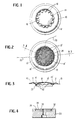
- the finished diaphragm has an annular outer securing edge flange 10 by which the diaphragm assembly is mounted, an annular semitorroidal portion 12, the interrupted, depressed ring area 14 with circumscribing and interrupting upwardly struck flute portions 16 and, finally, the central dome portion 18.
- the thin film from which the larger circular body is made is a synthetic resinous material, preferably processed from ULTEM 1000 (unmodified) available from General Electric Company, a polyetherimide resin having exceptional tensile and flexural strengths.
- the thin film is preferably about .0005 inch thick and is drawn under heat and pressure to the final shape shown.
- the areas 10, 14, 16 and 18 bear the brunt of the pressure and consequently are drawn the most.
- Not shown in Figure 1 is the central patch and the voice coil, but the former overlies the central dome portion 18 and the latter is concentric with and directly beneath the interrupted depressed ring areas 14.
- the two leads from the voice coil are shown by the lines 20 which are dashed in those regions in which they underlie the diaphragm and are solid where they project beyond the diaphragm.
- the adhesive employed to adhere the voice coil to the interrupted undersurface 22 of the diaphragm assembly (see Figure 3) is available from LOCTITE and preferably is an instant adhesive known as PRISM 403.
- FIG. 2 and 3 a plan view of the finished diaphragm and a section as indicated in Figure 2 are shown.
- the larger circular body is first placed in registered position on the smaller, preliminarily deformed circular patch.
- the smaller circular body is first plastically deformed (pressure only) so that it takes on the shape generally of the flutes 16 and the interrupted portions 14.
- the circular patch entity is then registered with the larger circular portion and the multi-layer entity is finally-deformed between the male and female dies so that it is deformed into final shape as indicated in Figure 1-3 before the voice coil 23 is adhered in position as indicated in Figure 3.
- the peripheral edge 24 of the circular patch (purposely omitted from Figure 1 for clarity) as shown in Figure 2, is coaxial with but lies just outside the boundaries of the flutes 16 and of the interrupted portions 14.
- the central patch has interrupted depressed portions 14' and flutes 16' which are merged onto and formed simultaneously with the portions 14 and 16 previously described in conjunction with Figure 1 as is the integrated body 18' of the circular patch formed simultaneously and integrated with the domed body 18 of Figure 1.
- the domed central patch 18' and the domed body portion 18 are shown as a single thickness because they are integral at this time.
- the diaphragm, minus the voice coil can easily be handled at this time and the voice coil can be adhered in place on and concentric with the interrupted surface 22 and with its leads 20 adhered to the undersurface of the edge flange 10.
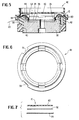
- the magnet assembly is shown in Figure 4. It comprises the high permeability steel cup 30 having the upper recess 32 which receives the Neodymium-Iron-Boron magnet 34 and the high permeability pole piece 36.
- the cup 30 and pole piece 36 may be made of 1215 steel.
- the annular air gap 38 receives the voice coil 23 with little radial clearance (typically about .045"), the internal diameter of the cup recess 32 being about .765" in a typical microphone.
- the magnet 34 is of .670" diameter and of .100" in thickness or height and it, as well as the cup 30 and the pole piece 36, may be provided with a central through bore or aperture as shown.
- the voice coil would have about 350 turns of copper wire in four coil layers, the wire size being 50 AWG with polyvinylbutyral bond.
- FIG. 5 shows the assembled microphone.
- the cup 30 of the magnet assembly is received in the bottom recess 40 of housing 42 and bottoms against the overhang 44.
- the cover 46 has an internal ledge 48 which clamps the edge 10 of the larger circular body peripherally against the housing face 50, the elevated wall 52 of the housing cover providing clearance for the motion of the diaphragm and being provided with a ring of apertures 54 to allow the pressure waves to impinge upon the diaphragm.
- the diaphragm assembly In equilibrium position, the diaphragm assembly is engaged by the support structure only at its peripheral edge 10 so that the diaphragm is free to flex in both directions normal to its surface.
- the housing 42 is provided with a pair of vertical recesses, 90° apart, to receive the voice coil leads 20 for soldering. Other housing parts may be provided as deemed necessary or desirable.
- Figure 6 is a plan view of the housing 42.
- the preliminary laminate consists of the thin film 60 of synthetic resinous material ULTEM 1000 and the spray-applied adhesive SCOTCH-GRIP 1099-L (about .001 " thick) is indicated at 62.
- the metal wire mesh material is indicated at 64. This material is 50 mesh stainless steel wire having a diameter of .0012" and of a roll width of 40", normally used for electrostatic shielding and available from the Swiss company TETKO INC.
- the ULTEM 1000 material with the 1099-L adhesive applied thereto and air dried is hot-ironed onto the mesh material so that the preliminary laminate is tacked to the synthetic resinous material.
- the ratio of diameter-to-height for the permanent magnet typically will be about 7:1 whereas this ratio for the voice coil is typically about 10:1.
- the ratios specified for the magnet and voice coil lead to the condition wherein the thickness or height of the voice coil is about 70% that of the magnet, or .070", taking into account that the inside diameter of the voice coil must be slightly larger (.045" typically) than the outside diameter of the magnet.
- the wire mesh-reinforced central dome should be about 40% of the total area of the diaphragm. This obtains sufficient stiffening to meet the objectives of the invention while maintaining the overall mass of the diaphragm-plus-voice-coil to achieve a dynamic microphone competitive in performance with modern condenser-type microphone designs.
Landscapes
- Engineering & Computer Science (AREA)
- Physics & Mathematics (AREA)
- Acoustics & Sound (AREA)
- Signal Processing (AREA)
- Manufacturing & Machinery (AREA)
- Multimedia (AREA)
- Audible-Bandwidth Dynamoelectric Transducers Other Than Pickups (AREA)
- Piezo-Electric Transducers For Audible Bands (AREA)
- Electric Double-Layer Capacitors Or The Like (AREA)
- Pressure Sensors (AREA)
- Monitoring And Testing Of Exchanges (AREA)
- Holo Graphy (AREA)
- Secondary Cells (AREA)
- Photovoltaic Devices (AREA)
- Use Of Switch Circuits For Exchanges And Methods Of Control Of Multiplex Exchanges (AREA)
- Time-Division Multiplex Systems (AREA)
Abstract
Description
- This invention is directed to microphones of the dynamic or moving-coil type and to the method of making them.
- It is traditional in such microphones to employ AlNiCo magnet structure and small area or diameter diaphragms. A small area diaphragm is beneficial because it means that both the diaphragm and voice coil attached to it present low mass so that the microphone is relatively insensitive to handling or to shock which could produce spurious noise. At the same time, a small diameter voice coil is compatible with AlNiCo magnets which require a high ratio of height-to-diameter (i.e., a "cylindrical" shape) in order to avoid the serious effects of self-demagnetization. Unfortunately, AlNiCo magnet designs also have a low level of flux density in the voice coil gap so that these traditional microphones have inferior acoustic sensitivity compared with modern microphones such as the "condenser" designs. Even if one were to increase the diameter of the AlNiCo magnet to improve the acoustic sensitivity, the penalties paid in increased magnet and consequent microphone sizes, not to mention the penalties paid in increased masses due to increased sizes of both the diaphragm and the voice coil, plus the penalty paid in increased mass due to the need to stiffen or compensate for the increased diameter of the diaphragm, render that approach impractical.
- Thus, it will be seen that features of both the diaphragm and of the magnetic circuitry play interrelated and mutually incompatible if not mutually exclusive parts in the efficacy of dynamic microphones insofar as improvements in their acoustic sensitivity and decrease in their handling or shock sensitivity are concerned. The prime function of a microphone diaphragm is to act as a receptor for acoustic pressure waves and to convert such waves into physical force or motion at the attached transducer, in this case the voice coil in its magnetic air gap. The diaphragm must have sufficient stiffness in the plane of its major face so that it will behave as a piston and, on the other hand, the means used to support the edge of the diaphragm in the direction normal to its major face must be compliant as possible to permit easy travel of the diaphragm in such normal direction. At the same time, the diaphragm and its edge mounting must be relatively rigid radially to prevent radial motion of the voice coil and to confine its motion in the axis of the air gap. The diaphragm and its edge mounting must also be resilient enough to return the coil axially to its mid-position at the frequency and amplitude of the acoustic waves bring treated, due regard being had for the overall mass of the whole moving system.
- I have discovered that it is possible to make an improved dynamic microphone having increased acoustic sensitivity and a low level of shock or of handling sensitivity if fabrication techniques involving the use of diaphragm lamination employing a layer of metal mesh is combined with the use of a Neodymium-Iron-Boron magnet having a "coin" shape (i.e., having a high ratio of diameter-to-height) and a voice coil having a diameter accepting the magnet.
- It is accordingly an object of this invention to provide an improved dynamic microphone employing a Neodymium-Iron-Boron magnet of coin shape in association with a voice coil of large internal diameter receiving such magnet and a diaphragm of low mass stiffened by a layer of metal mesh.
- Another object of the invention resides in the incorporation of a thin-wire metal mesh as a component of a domed layer of a diaphragm laminate surrounded by a semitorroidal annulus.
- In another aspect of the invention, an objective is to provide an improved dynamic microphone using a coin-shaped or wafer-like permanent magnet in association with a diaphragm having a multi-layer dome central portion incorporating a layer of thin wire metal mesh carrying a voice coil of large diameter and small height, the ratio of diameter-to-height being at least about 10:1.
- Another object of this invention is to provide an improved dynamic microphone employing a Neodymium-Iron-Boron permanent magnet having a ratio of diameter-to-height which is at least about 7:1 in conjunction with a voice coil of a diameter slightly larger than that of the magnet and in which the central portion of the diaphragm carrying the voice coil is stiffened by a dome shape in which a layer of thin-wire metal mesh is incorporated.
- Another object of the invention is to provide an improved dynamic microphone according to the immediately preceding object wherein the dome shape encompasses about 40% of the total area of the diaphragm.
- Other objects and advantages of this invention will be apparent as this description proceeds.
-
- Figure 1 is plan view of the diaphragm of the invention, the central patch being omitted for the sake of clarity;
- Figure 2 is a view similar to Fig. 1 but with the central patch;
- Figure 3 is a cross-section of the finally shaped diaphragm with the voice coil adhered in place;
- Figure 4 is a cross-section of the magnet assembly;
- Figure 5 is a cross-sectional view of the assembled microphone;
- Figure 6 is a plan view of the housing; and
- Figure 7 is an exploded detail of the central patch construction.
- Before describing the structural details of this invention by reference to the drawing Figures, it is well to discuss the method of making the invention. Such method involves the step of forming a preliminary laminate which is a thin film of synthetic resinous material having a plastic adhesive (adhesive such as SCOTCH-GRIP 1099-L nitrile rubber base adhesive available from 3M) sprayed onto one face thereof, with drying, and a sheet of fine mesh metal wire in face-to-face contact with the dry adhesive and initially tacked to it by hot ironing the thin film with applied adhesive onto the wire mesh. This preliminary laminate is cut, by stamping, into circular central patches and each central patch is plastically deformed, without heat, partially into final shape. A larger circular body is stamped from a separate thin film of the synthetic resinous material. The partially deformed patch serves to allow accurate positioning of the larger circular body centrally of it. The result is a multi-layer entity in which the mesh side of the partially deformed central patch engages centrally on the larger circular body. The multi-layer entity is then subjected to heat and pressure between a lower male die and an upper female die forming the final diaphragm shape by thermal and plastic deformation while penetrating the adhesive through the mesh and curing it to bond the synthetic resinous layer of the central patch to the synthetic resinous layer of the larger circular body together (while penetrating and capture-bonding the mesh).
- The voice coil is wound in multi-layer form and adhered in that form by the polyvinylbutyral coating on such wire. The diameter of a voice coil is slightly smaller than the diameter of a circular patch. The voice coil is wound with an even number of coil layers so that the two leads at the opposite ends of the coil wire are at the same end of the coil height and therefore may lie close to or against the face opposite the face contacted by the mesh and extend radially outward in free fashion for ultimate connection to the output circuitry in conventional fashion. However, the delicate leads may be locally adhered to a peripheral edge portion of the larger circular body so as to anchor them securely after the voice coil is adhered in place and before they are soldered in place.
- With reference to Figure 1, the final shape of the diaphragm will be seen, although it is to be understood that the drawing figure omits the overlying central patch for the sake of clarity. As shown, the finished diaphragm has an annular outer
securing edge flange 10 by which the diaphragm assembly is mounted, an annularsemitorroidal portion 12, the interrupted,depressed ring area 14 with circumscribing and interrupting upwardly struckflute portions 16 and, finally, thecentral dome portion 18. As noted above, the thin film from which the larger circular body is made is a synthetic resinous material, preferably processed from ULTEM 1000 (unmodified) available from General Electric Company, a polyetherimide resin having exceptional tensile and flexural strengths. The thin film is preferably about .0005 inch thick and is drawn under heat and pressure to the final shape shown. Theareas central dome portion 18 and the latter is concentric with and directly beneath the interrupteddepressed ring areas 14. The two leads from the voice coil are shown by thelines 20 which are dashed in those regions in which they underlie the diaphragm and are solid where they project beyond the diaphragm. The adhesive employed to adhere the voice coil to theinterrupted undersurface 22 of the diaphragm assembly (see Figure 3) is available from LOCTITE and preferably is an instant adhesive known as PRISM 403. - Referring to Figures 2 and 3, a plan view of the finished diaphragm and a section as indicated in Figure 2 are shown. As noted before, the larger circular body is first placed in registered position on the smaller, preliminarily deformed circular patch. For this registering, the smaller circular body is first plastically deformed (pressure only) so that it takes on the shape generally of the
flutes 16 and the interruptedportions 14. The circular patch entity is then registered with the larger circular portion and the multi-layer entity is finally-deformed between the male and female dies so that it is deformed into final shape as indicated in Figure 1-3 before thevoice coil 23 is adhered in position as indicated in Figure 3. - That is to say, the
peripheral edge 24 of the circular patch (purposely omitted from Figure 1 for clarity) as shown in Figure 2, is coaxial with but lies just outside the boundaries of theflutes 16 and of theinterrupted portions 14. After forming into final shape, the central patch has interrupted depressed portions 14' and flutes 16' which are merged onto and formed simultaneously with theportions domed body 18 of Figure 1. In Figure 3, the domed central patch 18' and thedomed body portion 18 are shown as a single thickness because they are integral at this time. The diaphragm, minus the voice coil, can easily be handled at this time and the voice coil can be adhered in place on and concentric with theinterrupted surface 22 and with itsleads 20 adhered to the undersurface of theedge flange 10. - The magnet assembly is shown in Figure 4. It comprises the high
permeability steel cup 30 having theupper recess 32 which receives the Neodymium-Iron-Boronmagnet 34 and the highpermeability pole piece 36. Thecup 30 andpole piece 36 may be made of 1215 steel. Theannular air gap 38 receives thevoice coil 23 with little radial clearance (typically about .045"), the internal diameter of the cup recess 32 being about .765" in a typical microphone. For this typical microphone, themagnet 34 is of .670" diameter and of .100" in thickness or height and it, as well as thecup 30 and thepole piece 36, may be provided with a central through bore or aperture as shown. Also, it should be noted that the voice coil would have about 350 turns of copper wire in four coil layers, the wire size being 50 AWG with polyvinylbutyral bond. - Figure 5 shows the assembled microphone. The
cup 30 of the magnet assembly is received in thebottom recess 40 ofhousing 42 and bottoms against theoverhang 44. Thecover 46 has aninternal ledge 48 which clamps theedge 10 of the larger circular body peripherally against thehousing face 50, the elevatedwall 52 of the housing cover providing clearance for the motion of the diaphragm and being provided with a ring ofapertures 54 to allow the pressure waves to impinge upon the diaphragm. In equilibrium position, the diaphragm assembly is engaged by the support structure only at itsperipheral edge 10 so that the diaphragm is free to flex in both directions normal to its surface. Thehousing 42 is provided with a pair of vertical recesses, 90° apart, to receive the voice coil leads 20 for soldering. Other housing parts may be provided as deemed necessary or desirable. Figure 6 is a plan view of thehousing 42. - To complete the disclosure of the microphone, Figure 7 has been included to illustrate, in exploded fashion, the details of the preliminary laminate from which the central patches are stamped or cut. As shown, the preliminary laminate consists of the
thin film 60 of synthetic resinous material ULTEM 1000 and the spray-applied adhesive SCOTCH-GRIP 1099-L (about .001 " thick) is indicated at 62. Lastly, the metal wire mesh material is indicated at 64. This material is 50 mesh stainless steel wire having a diameter of .0012" and of a roll width of 40", normally used for electrostatic shielding and available from the Swiss company TETKO INC. As noted before, the ULTEM 1000 material with the 1099-L adhesive applied thereto and air dried is hot-ironed onto the mesh material so that the preliminary laminate is tacked to the synthetic resinous material. - Dimensionally, the ratio of diameter-to-height for the permanent magnet typically will be about 7:1 whereas this ratio for the voice coil is typically about 10:1. Taking .100" for the magnet thickness or height as a practical lower limit for the Neodymium-Iron-Boron magnet before self-demagnetization becomes a controlling factor, the ratios specified for the magnet and voice coil lead to the condition wherein the thickness or height of the voice coil is about 70% that of the magnet, or .070", taking into account that the inside diameter of the voice coil must be slightly larger (.045" typically) than the outside diameter of the magnet.
- Lastly, it should be noted that with the specific materials specified herein and in accord with the preferred configuration and dimensions detailed herein, it can be said that the wire mesh-reinforced central dome should be about 40% of the total area of the diaphragm. This obtains sufficient stiffening to meet the objectives of the invention while maintaining the overall mass of the diaphragm-plus-voice-coil to achieve a dynamic microphone competitive in performance with modern condenser-type microphone designs.
Claims (11)
- The method of making a dynamic microphone which comprises the steps of forming a diaphragm body of thin synthetic resinous sheet material of high tensile and flexural strength, forming a multi-layer central portion of thin synthetic resinous material and thin-wire metal mesh, contacting the central portion centrally of the diaphragm body and integrating while deforming both so that they are domed with the diaphragm body on the concave side of the central portion.
- The method of making a dynamic microphone as defined in claim 1 wherein the thin-wire metal mesh is in face-to-face contact with the diaphragm body.
- The method of making a dynamic microphone as defined in claim 2 including the steps of forming a voice coil having a diameter commensurate with that of the domed area of the integrated diaphragm and affixing the voice coil to the thin synthetic resinous material of the body in circumscribing relation to the domed area.
- The method of making a dynamic microphone as defined in claim 3 wherein the permanent magnet is Neodymium-Iron-Boron.
- The method of making a dynamic microphone which comprises the steps of forming a permanent magnet having a high ratio of diameter-to-height, forming a diaphragm body of thin synthetic resinous sheet material of high tensile and flexural strength, forming a multi-layer central portion of thin synthetic resinous material and thin-wire metal mesh, contacting the central portion centrally of the diaphragm body and integrating while deforming both so that they are domed with the diaphragm body on the concave side of the central portion, the central portion being less than one-half the total area of the diaphragm body, forming a voice coil having a diameter and a diameter-to-height ratio greater than those of the magnet, affixing the voice coil in circumscribing relation to the domed area and on the convex side thereof, locating the voice coil to surround the magnet, and fixing the periphery of the diaphragm relative to the magnet.
- The method according to claim 5 wherein the magnet presents North and South poles on its larger faces and including the step of enclosing the magnet partially with high permeability material so as to leave an air gap within which the voice coil is partially received.
- The method as defined in claim 6 wherein the diameter-to-height ratio of the magnet is about 7:1 and the diameter-to-height ratio of the voice coil is about 10:1.
- A microphone construction comprising the combination of a diaphragm having a domed central portion and a surrounding attachment portion whereby the diaphragm is free to vibrate in a plane normal to the diaphragm, an annular voice coil attached to and circumscribing the central portion on the concave side thereof, and a fixed permanent magnet disposed within said voice coil, said magnet being of neodymium-iron-boron composition and of disc shape, the voice coil having an internal diameter many times greater than its thickness and the thickness of the magnet being greater than the thickness of the voice coil.
- A microphone construction as defined in claim 8 wherein the area encompassed by the central portion is about 40% of the total area of the diaphragm.
- A microphone construction as defined in claim 9 wherein the ratio of diameter-to-height of the magnet is at least 7:1.
- A microphone construction as defined in claim 10 wherein the ratio of diameter-to-height of the voice coil is about 10:1.
Applications Claiming Priority (2)
| Application Number | Priority Date | Filing Date | Title |
|---|---|---|---|
| US07/466,599 US5033093A (en) | 1990-01-17 | 1990-01-17 | Compact microphone and method of manufacture |
| US466599 | 1990-01-17 |
Publications (3)
| Publication Number | Publication Date |
|---|---|
| EP0446515A2 true EP0446515A2 (en) | 1991-09-18 |
| EP0446515A3 EP0446515A3 (en) | 1992-08-26 |
| EP0446515B1 EP0446515B1 (en) | 1994-08-10 |
Family
ID=23852381
Family Applications (1)
| Application Number | Title | Priority Date | Filing Date |
|---|---|---|---|
| EP90304814A Expired - Lifetime EP0446515B1 (en) | 1990-01-17 | 1990-05-03 | Dynamic microphone and method of making the same |
Country Status (11)
| Country | Link |
|---|---|
| US (1) | US5033093A (en) |
| EP (1) | EP0446515B1 (en) |
| JP (1) | JPH0738760B2 (en) |
| KR (2) | KR930009631B1 (en) |
| AT (1) | ATE109935T1 (en) |
| AU (1) | AU5592490A (en) |
| BR (1) | BR9002691A (en) |
| CA (1) | CA2011690C (en) |
| DE (1) | DE69011502T2 (en) |
| IE (1) | IE64602B1 (en) |
| PT (1) | PT94141A (en) |
Cited By (1)
| Publication number | Priority date | Publication date | Assignee | Title |
|---|---|---|---|---|
| US6185809B1 (en) | 1996-06-19 | 2001-02-13 | Akg Acoustics Gmbh | Method of manufacturing a diaphragm for an electroacoustic transducer |
Families Citing this family (17)
| Publication number | Priority date | Publication date | Assignee | Title |
|---|---|---|---|---|
| DE4234069A1 (en) * | 1992-10-09 | 1994-04-14 | Nokia Deutschland Gmbh | Cone speaker in lightweight design |
| JP2001346291A (en) * | 2000-06-05 | 2001-12-14 | Sony Corp | Speaker device |
| US6496590B2 (en) | 2000-12-08 | 2002-12-17 | Jl Audio, Inc. | Loudspeaker with improved diaphragm |
| US20040091678A1 (en) * | 2002-11-12 | 2004-05-13 | Jordan James Lowell | Universal cover |
| USD518028S1 (en) * | 2004-05-07 | 2006-03-28 | Gp Acoustic (U.K.) Ltd. | Loudspeaker |
| JP2006013666A (en) * | 2004-06-23 | 2006-01-12 | Matsushita Electric Ind Co Ltd | Electroacoustic transducer and electronic device using the same |
| DE102005040293B3 (en) * | 2005-08-21 | 2006-09-21 | Hahn-Meitner-Institut Berlin Gmbh | Sound sensor has magnetoresistive sensor whereby sensor material of magnetoresistive sensor is an electrically anisotropic conductor, whereby the electric field and the magnetic field is applied to sensor material |
| US20080053745A1 (en) * | 2006-08-30 | 2008-03-06 | Takumu Tada | Electroacoustic transducer and diaphragm |
| USD567228S1 (en) * | 2007-02-21 | 2008-04-22 | J&M Corporation | Speaker grill |
| CN101816187B (en) * | 2007-10-09 | 2013-09-11 | 日东电工株式会社 | Sound passing member utilizing waterproof sound passing membrane and process for manufacturing the same |
| USD601133S1 (en) * | 2008-03-07 | 2009-09-29 | Kabushiki Kaisha Audio-Technica | Headphone |
| CN102118671B (en) * | 2009-12-30 | 2015-08-12 | 富准精密工业(深圳)有限公司 | Sound film |
| JP5879187B2 (en) * | 2012-04-25 | 2016-03-08 | 株式会社オーディオテクニカ | Speaker diaphragm and headphones |
| CN204425608U (en) * | 2015-02-02 | 2015-06-24 | 瑞声光电科技(常州)有限公司 | Loudspeaker enclosure |
| CN109451403B (en) * | 2018-09-18 | 2020-05-26 | 海菲曼(天津)科技有限公司 | Vibration diaphragm structure of transducer of miniature flat-panel loudspeaker and loudspeaker with vibration diaphragm of transducer |
| US11758332B1 (en) * | 2022-04-15 | 2023-09-12 | United States Of America As Represented By The Secretary Of The Navy | Biodegradable microphone |
| US20250080891A1 (en) * | 2023-08-31 | 2025-03-06 | Logitech Europe S.A. | Dynamic microphone capsule suspension structure |
Family Cites Families (18)
| Publication number | Priority date | Publication date | Assignee | Title |
|---|---|---|---|---|
| US1487013A (en) * | 1921-11-12 | 1924-03-18 | Cliftophone Ltd | Diaphragm for sound-recording and sound-reproducing instruments |
| US3041418A (en) * | 1960-01-14 | 1962-06-26 | Rca Corp | Transducers |
| US3313018A (en) * | 1962-07-06 | 1967-04-11 | Tibbetts Industries | Method of making diaphragm means for acoustic translating devices |
| US3513270A (en) * | 1965-05-08 | 1970-05-19 | Sennheiser Electronic | Microphone diaphragm including spacer means between diaphragm and voice coil |
| US3586794A (en) * | 1967-11-04 | 1971-06-22 | Sennheiser Electronic | Earphone having sound detour path |
| JPS5229724A (en) * | 1975-09-02 | 1977-03-05 | Matsushita Electric Ind Co Ltd | Speaker dome diaphragm |
| US3989905A (en) * | 1975-12-15 | 1976-11-02 | Shure Brothers Inc. | Microphone |
| JPS5345227A (en) * | 1976-10-05 | 1978-04-22 | Matsushita Electric Ind Co Ltd | Vibrating plate for spaker |
| US4532383A (en) * | 1980-01-04 | 1985-07-30 | Willy Erazm A | Electroacoustic transducer having a variable thickness diaphragm |
| FR2473242A1 (en) * | 1980-01-08 | 1981-07-10 | Thomson Csf | ACTIVE DOME ELECTROACOUSTIC TRANSDUCER |
| JPS572579A (en) * | 1980-06-05 | 1982-01-07 | Sanyo Electric Co Ltd | Manufacture of junction type field effect transistor |
| CA1165248A (en) * | 1980-10-31 | 1984-04-10 | Shingo Watanabe | Electro-acoustic transducer |
| FR2511570A1 (en) * | 1981-08-11 | 1983-02-18 | Thomson Csf | ELECTROACOUSTIC TRANSDUCER WITH PIEZOELECTRIC POLYMER |
| JPS61278296A (en) * | 1985-06-04 | 1986-12-09 | Matsushita Electric Ind Co Ltd | Directional dynamic microphone unit |
| US4761817A (en) * | 1986-01-27 | 1988-08-02 | Harman International Industries, Incorporated | Diaphragm structure for a transducer |
| US4817165A (en) * | 1987-01-27 | 1989-03-28 | Amalaha Leonard D | Acoustic speaker device with a diaphragm having a spider web type core |
| JPH0164294U (en) * | 1987-10-19 | 1989-04-25 | ||
| GB2214724A (en) * | 1988-01-28 | 1989-09-06 | Custom Dev Ltd | Permanent magnet electric motor |
-
1990
- 1990-01-17 US US07/466,599 patent/US5033093A/en not_active Expired - Fee Related
- 1990-03-07 CA CA002011690A patent/CA2011690C/en not_active Expired - Fee Related
- 1990-04-27 IE IE155390A patent/IE64602B1/en not_active IP Right Cessation
- 1990-04-27 JP JP2114955A patent/JPH0738760B2/en not_active Expired - Lifetime
- 1990-05-03 DE DE69011502T patent/DE69011502T2/en not_active Expired - Fee Related
- 1990-05-03 EP EP90304814A patent/EP0446515B1/en not_active Expired - Lifetime
- 1990-05-03 AT AT90304814T patent/ATE109935T1/en not_active IP Right Cessation
- 1990-05-11 KR KR1019900006749A patent/KR930009631B1/en not_active Expired - Fee Related
- 1990-05-24 PT PT94141A patent/PT94141A/en not_active Application Discontinuation
- 1990-05-28 AU AU55924/90A patent/AU5592490A/en not_active Abandoned
- 1990-06-07 BR BR909002691A patent/BR9002691A/en unknown
-
1991
- 1991-01-21 KR KR1019910000965A patent/KR930009630B1/en not_active Expired - Fee Related
Cited By (1)
| Publication number | Priority date | Publication date | Assignee | Title |
|---|---|---|---|---|
| US6185809B1 (en) | 1996-06-19 | 2001-02-13 | Akg Acoustics Gmbh | Method of manufacturing a diaphragm for an electroacoustic transducer |
Also Published As
| Publication number | Publication date |
|---|---|
| CA2011690A1 (en) | 1993-04-27 |
| KR930009631B1 (en) | 1993-10-07 |
| EP0446515B1 (en) | 1994-08-10 |
| JPH0738760B2 (en) | 1995-04-26 |
| EP0446515A3 (en) | 1992-08-26 |
| AU5592490A (en) | 1991-07-18 |
| KR910015189A (en) | 1991-08-31 |
| ATE109935T1 (en) | 1994-08-15 |
| US5033093A (en) | 1991-07-16 |
| PT94141A (en) | 1992-02-28 |
| DE69011502D1 (en) | 1994-09-15 |
| JPH03218200A (en) | 1991-09-25 |
| KR930009630B1 (en) | 1993-10-07 |
| IE64602B1 (en) | 1995-08-23 |
| BR9002691A (en) | 1991-08-20 |
| KR920015948A (en) | 1992-08-27 |
| DE69011502T2 (en) | 1995-03-16 |
| CA2011690C (en) | 1993-04-27 |
| IE901553A1 (en) | 1991-07-17 |
Similar Documents
| Publication | Publication Date | Title |
|---|---|---|
| US5033093A (en) | Compact microphone and method of manufacture | |
| US4427845A (en) | Dynamic microphone | |
| US4330878A (en) | Sound producing device for watches | |
| CA1160732A (en) | Securing of lead wires to electro-acoustic transducers | |
| US6587570B1 (en) | Electroacoustic transducer | |
| JPS60171900A (en) | speaker | |
| JPS5942797Y2 (en) | flat speaker | |
| KR100443366B1 (en) | Double Side Micro-Speaker Unit | |
| US5270676A (en) | Method of making elements of a magnetic circuit in a loudspeaker | |
| JPS58157296A (en) | Speaker | |
| JPS5831800B2 (en) | Dome-shaped speaker manufacturing equipment | |
| JPS5852792Y2 (en) | speaker | |
| JPH04639Y2 (en) | ||
| JPH0112464Y2 (en) | ||
| JP2574930Y2 (en) | Electromagnetic sound transducer | |
| JPS646640Y2 (en) | ||
| JPS58162197A (en) | Assembling method of speaker | |
| KR100336987B1 (en) | Speaker | |
| EP0926924B1 (en) | Speaker | |
| JPS5852791Y2 (en) | speaker | |
| JPS5819916Y2 (en) | dome speaker | |
| JPS5819911Y2 (en) | Diaphragm for speaker | |
| JPH0749912Y2 (en) | Piezoelectric electroacoustic transducer | |
| JPS6311807Y2 (en) | ||
| JP2538604Y2 (en) | Speaker |
Legal Events
| Date | Code | Title | Description |
|---|---|---|---|
| PUAI | Public reference made under article 153(3) epc to a published international application that has entered the european phase |
Free format text: ORIGINAL CODE: 0009012 |
|
| AK | Designated contracting states |
Kind code of ref document: A2 Designated state(s): AT BE CH DE DK ES FR GB GR IT LI LU NL SE |
|
| PUAL | Search report despatched |
Free format text: ORIGINAL CODE: 0009013 |
|
| AK | Designated contracting states |
Kind code of ref document: A3 Designated state(s): AT BE CH DE DK ES FR GB GR IT LI LU NL SE |
|
| 17P | Request for examination filed |
Effective date: 19930113 |
|
| 17Q | First examination report despatched |
Effective date: 19930505 |
|
| GRAA | (expected) grant |
Free format text: ORIGINAL CODE: 0009210 |
|
| AK | Designated contracting states |
Kind code of ref document: B1 Designated state(s): AT BE CH DE DK ES FR GB GR IT LI LU NL SE |
|
| PG25 | Lapsed in a contracting state [announced via postgrant information from national office to epo] |
Ref country code: IT Free format text: LAPSE BECAUSE OF FAILURE TO SUBMIT A TRANSLATION OF THE DESCRIPTION OR TO PAY THE FEE WITHIN THE PRE;WARNING: LAPSES OF ITALIAN PATENTS WITH EFFECTIVE DATE BEFORE 2007 MAY HAVE OCCURRED AT ANY TIME BEFORE 2007. THE CORRECT EFFECTIVE DATE MAY BE DIFFERENT FROM THE ONE RECORDED.SCRIBED TIME-LIMIT Effective date: 19940810 Ref country code: ES Free format text: THE PATENT HAS BEEN ANNULLED BY A DECISION OF A NATIONAL AUTHORITY Effective date: 19940810 Ref country code: NL Effective date: 19940810 Ref country code: GR Free format text: LAPSE BECAUSE OF FAILURE TO SUBMIT A TRANSLATION OF THE DESCRIPTION OR TO PAY THE FEE WITHIN THE PRESCRIBED TIME-LIMIT Effective date: 19940810 Ref country code: LI Effective date: 19940810 Ref country code: DK Effective date: 19940810 Ref country code: FR Effective date: 19940810 Ref country code: BE Effective date: 19940810 Ref country code: CH Effective date: 19940810 |
|
| REF | Corresponds to: |
Ref document number: 109935 Country of ref document: AT Date of ref document: 19940815 Kind code of ref document: T |
|
| REF | Corresponds to: |
Ref document number: 69011502 Country of ref document: DE Date of ref document: 19940915 |
|
| PG25 | Lapsed in a contracting state [announced via postgrant information from national office to epo] |
Ref country code: SE Effective date: 19941110 |
|
| REG | Reference to a national code |
Ref country code: CH Ref legal event code: PL |
|
| EN | Fr: translation not filed | ||
| NLV1 | Nl: lapsed or annulled due to failure to fulfill the requirements of art. 29p and 29m of the patents act | ||
| PG25 | Lapsed in a contracting state [announced via postgrant information from national office to epo] |
Ref country code: LU Free format text: LAPSE BECAUSE OF NON-PAYMENT OF DUE FEES Effective date: 19950531 |
|
| PLBE | No opposition filed within time limit |
Free format text: ORIGINAL CODE: 0009261 |
|
| STAA | Information on the status of an ep patent application or granted ep patent |
Free format text: STATUS: NO OPPOSITION FILED WITHIN TIME LIMIT |
|
| 26N | No opposition filed | ||
| PGFP | Annual fee paid to national office [announced via postgrant information from national office to epo] |
Ref country code: GB Payment date: 19960424 Year of fee payment: 7 |
|
| PGFP | Annual fee paid to national office [announced via postgrant information from national office to epo] |
Ref country code: DE Payment date: 19960513 Year of fee payment: 7 |
|
| PGFP | Annual fee paid to national office [announced via postgrant information from national office to epo] |
Ref country code: AT Payment date: 19960514 Year of fee payment: 7 |
|
| PG25 | Lapsed in a contracting state [announced via postgrant information from national office to epo] |
Ref country code: AT Effective date: 19970503 Ref country code: GB Effective date: 19970503 |
|
| GBPC | Gb: european patent ceased through non-payment of renewal fee |
Effective date: 19970503 |
|
| PG25 | Lapsed in a contracting state [announced via postgrant information from national office to epo] |
Ref country code: DE Free format text: LAPSE BECAUSE OF NON-PAYMENT OF DUE FEES Effective date: 19980203 |