EP0446517B1 - Packer mit langem Setzweg - Google Patents
Packer mit langem Setzweg Download PDFInfo
- Publication number
- EP0446517B1 EP0446517B1 EP90308065A EP90308065A EP0446517B1 EP 0446517 B1 EP0446517 B1 EP 0446517B1 EP 90308065 A EP90308065 A EP 90308065A EP 90308065 A EP90308065 A EP 90308065A EP 0446517 B1 EP0446517 B1 EP 0446517B1
- Authority
- EP
- European Patent Office
- Prior art keywords
- packer
- mandrel
- housing
- shoe
- well bore
- Prior art date
- Legal status (The legal status is an assumption and is not a legal conclusion. Google has not performed a legal analysis and makes no representation as to the accuracy of the status listed.)
- Expired - Lifetime
Links
Images


Classifications
-
- E—FIXED CONSTRUCTIONS
- E21—EARTH OR ROCK DRILLING; MINING
- E21B—EARTH OR ROCK DRILLING; OBTAINING OIL, GAS, WATER, SOLUBLE OR MELTABLE MATERIALS OR A SLURRY OF MINERALS FROM WELLS
- E21B33/00—Sealing or packing boreholes or wells
- E21B33/10—Sealing or packing boreholes or wells in the borehole
- E21B33/12—Packers; Plugs
- E21B33/129—Packers; Plugs with mechanical slips for hooking into the casing
- E21B33/1294—Packers; Plugs with mechanical slips for hooking into the casing characterised by a valve, e.g. a by-pass valve
-
- E—FIXED CONSTRUCTIONS
- E21—EARTH OR ROCK DRILLING; MINING
- E21B—EARTH OR ROCK DRILLING; OBTAINING OIL, GAS, WATER, SOLUBLE OR MELTABLE MATERIALS OR A SLURRY OF MINERALS FROM WELLS
- E21B33/00—Sealing or packing boreholes or wells
- E21B33/10—Sealing or packing boreholes or wells in the borehole
- E21B33/12—Packers; Plugs
- E21B33/129—Packers; Plugs with mechanical slips for hooking into the casing
- E21B33/1291—Packers; Plugs with mechanical slips for hooking into the casing anchor set by wedge or cam in combination with frictional effect, using so-called drag-blocks
- E21B33/1292—Packers; Plugs with mechanical slips for hooking into the casing anchor set by wedge or cam in combination with frictional effect, using so-called drag-blocks with means for anchoring against downward and upward movement
Definitions
- the present invention relates to packers for use in well bores and, more particularly, to a packer which allows manipulation of a tool below the packer by some reciprocation of the tool string without setting the packer.
- US-A-4619319 discloses a multiple purpose retrievable packer designed for testing, treating and squeezing operations comprising a housing; a packer mandrel longitudinally slidably disposed with respect to the housing; an operating mandrel longitudinally slidably disposed in the housing and packer mandrel and adapted for connection to a tool string; packer means disposed on said packer mandrel for sealingly engaging the well bore when in a set position; and a packer shoe located between a position of the housing and the packer means to transmit longitudinal movement of the housing to the packer means to set the same.
- This packer is set by turning the work string to the right and setting down weight. Pressure applied below the packer forces hydraulic holddown slips against the casing. This helps prevent the packer from being pumped up the well bore. A straight upward pull releases the packer.
- a concentric bypass is built into the packer, and this allows the fluid to bypass between two concentric mandrels, requiring all circulated fluid to go around the bottom of the packer.
- the bypass is locked in the open position and cannot close until the setting action engages the lower mechanical slips.
- a large area through the bypass allows the packer to be run with a minimum of pressure surges being created.
- a pressure balancing system helps prevent the bypass from being pumped open.
- the packer has a relatively short setting stroke, and a portion of the outer housing forms an upper packer shoe.
- the bypass is closed and the shoe is forced downwardly against the packer elements squeezing them outwardly into a sealing position.
- the mechanical slips are forced outwardly to grippingly engage the well bore. Because of the relatively short setting stroke, manipulation of certain tools such as the Halliburton Services FO Frac System is not possible with this packer. Accordingly, there is a need for a packer of the general form described above, but with a relatively longer stroke which allows some manipulation of the tool string to actuate certain tools below the packer.
- the present invention is characterized in that the said packer shoe is slidably disposed on the packer mandrel and is initially longitudinally spaced from the said housing portion to permit some relative longitudinal movement of the housing and the packer mandrel prior to displacement of the shoe to set the packer.
- This construction allows for partial reciprocation of the operating mandrel and the housing as necessary, for actuating a tool which may be positioned below the packer, but without setting the packer.
- the packer preferably further comprises means for preventing relative rotation between the housing and packer mandrel.
- This means for preventing relative rotation may comprise one of the housing and the packer mandrel having lug means thereon, or extending therefrom, and the other of the housing and packer means having receiving means thereon for receiving the lug means and providing sliding engagement therebetween.
- the lug means is a lug or external spline on the packer mandrel
- the receiving means is a slot or internal spline in the housing.
- the packer mandrel may comprise a shoulder adjacent to the shoe so that relative upper movement thereof is prevented beyond the shoulder.
- the shoe is positioned adjacent to the packer means, and in the illustrated embodiment, is located between the shoulder and the packer means.
- the packer may further comprise mechanical slip means for grippingly engaging the well bore when in a set position, a drag block or drag block assembly for engaging a liner portion of the well bore and allowing relative movement between the housing and the operating mandrel, and hydraulic slip means for preventing upward movement of the packer in the event of increased pressure below the packer.
- the packer may also comprise bypass means for bypassing fluid through the packer when it is run into the well bore.
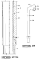
- Packer 10 is positioned in a well bore 12, generally defined by casing 13, at the end of a tool string 14. As seen in FIG. 1, well bore 12 may be deviated. Another tool or tools 16, such as the Halliburton Services FO Frac System, may be disposed below packer 10. As will be further described herein, packer 10 is designed for use with any tool which requires actuation by manipulation of the tool string without setting the packer, and it is not intended that the invention be limited to any particular tool below the packer. Packer 10 is eventually positioned in a liner portion 18 of well bore 12, and when set, packer 10 is in gripping and sealing engagement with bore 20 of liner 18.
- Packer 10 includes an outer housing assembly 22 with a packer mandrel assembly 24 slidably connected thereto. Packer means, such as packer elements 26, and a mechanical slip assembly 28 are disposed on packer mandrel assembly 24.
- Packer means such as packer elements 26, and a mechanical slip assembly 28 are disposed on packer mandrel assembly 24.
- a drag block assembly 30 is attached to the lower end of packer mandrel assembly 24.
- An operating mandrel assembly 32 is attached to tool string 14 and is slidably disposed in housing assembly 22, packer mandrel assembly 24 and drag block assembly 30.
- top adapter 34 At the upper end of packer 10, and forming the upper portion of operating mandrel assembly 32, is a top adapter 34.
- Top adapter 34 has a threaded bore 36 adapted for connection to tool string 14.
- Top adapter 34 is attached to upper mandrel 38 at threaded connection 40.
- a sealing means such as O-ring 42, provides sealing engagement between top adapter 34 and upper mandrel 38.
- Upper mandrel 38 has a first outside diameter 44 below threaded connection 40.
- Hydraulic body 46 extends into hydraulic body 46 which forms the upper portion of housing assembly 22.
- Hydraulic body 46 has a first bore 48 therein which is in close, spaced relationship to first outside diameter 44 of upper mandrel 38.
- a sealing means such as a plurality of O-rings 50, provides sealing engagement between upper mandrel 38 and hydraulic body 46.
- Hydraulic body 46 also defines a second bore 52 therein which is slightly larger than first bore 48.
- hydraulic body 46 defines a plurality of transverse openings 54 therein.
- An elongated recess 56 extends longitudinally along the outer surface of hydraulic body 46 and spans adjacent pairs of openings 54.
- each opening 54 Disposed in each opening 54 is a hydraulic slip 58.
- a sealing means such as O-ring 60, provides sealing engagement between each hydraulic slip 58 and a corresponding body 46 held in place by bolts 64.
- Holding strap 62 retains hydraulic slips 58 in openings 54.
- a biasing means such as a plurality of springs 66, is disposed in each opening 54 between holding strap 62 and the corresponding hydraulic slip 58 to bias the hydraulic slip radially inwardly toward inner mandrel 38.
- a lug receiving means such as a longitudinally extending internal slot or internal spline 68, which is engaged by a lug means, such as an outwardly extending lug or external spline 70 on upper mandrel 38. It will thus be seen that relative rotation between housing assembly 22 and operating mandrel assembly 32 is prevented.
- a lug receiving means such as a longitudinally extending internal slot or internal spline 68
- a lug means such as an outwardly extending lug or external spline 70 on upper mandrel 38.
- the lower end of upper mandrel 38 is attached to a balancing coupling 76 at threaded connection 78.
- a sealing means such as O-ring 80, provides sealing engagement therebetween.
- Coupling 76 defines a longitudinal passageway 82 therethrough which is in communication with annulus 75. Coupling 76 has an outside diameter 84.
- hydraulic body 46 is attached to an upper body 86 at threaded connection 88.
- a sealing means such as O-ring 90, provides sealing engagement therebetween.
- Upper body 86 defines a first bore 92 therein which is spaced radially outwardly from outside diameter 84 of balancing coupling 76. Disposed between first bore 92 and outside diameter 84 is a floating piston 94. Piston 94 is adapted for relative sliding engagement with first bore 92 and outside diameter 84. An outer sealing means, such as O-rings 96, provide sealing between piston 94 and first bore 92 of upper body 86. Referring now to FIG. 2C, an inner sealing means, such as O-rings 98, provides sealing between piston 94 and outside diameter 84 of balancing coupling 76. An enlarged portion 100 of coupling 76 defines an upwardly facing shoulder 102 thereon which is initially positioned adjacent to lower end 104 of piston 94.
- balancing coupling 76 is attached to a center mandrel 106 at threaded connection 108.
- a sealing means such as O-ring 110, provides sealing engagement between the center mandrel and balancing coupling.
- Center mandrel 106 has a first outside diameter 112.
- Balancing coupling 76 has a bore 114 therethrough which is spaced radially outwardly from first outside diameter 112 of center mandrel 106 such that an annulus 116 is defined therebetween. It will be seen that annulus 116 is in communication with passageway 82 in balancing coupling 76.
- a seal ring retainer 118 is attached to the lower end of balancing coupling 76 at threaded connection 120.
- Retainer 118 defines a bore 122 therethrough which is spaced radially outwardly from first outside diameter 112 of center mandrel 106 such that an annulus 124 is defined therebetween which, as will be seen by those skilled in the art, is in communication with annulus 116.
- Seal ring retainer 118 holds a bypass seal 126 adjacent to enlarged portion 100 of balancing coupling 76.
- Bypass seal 126 has an annular sealing element 128 made of elastomeric material or the like.
- First bore 92 in upper body 86 is spaced radially outwardly from first outside diameter 112 of center mandrel 106 such that a generally annular cavity 130 is defined therebetween below piston 94.
- Upper body 86 defines a plurality of transverse bypass ports or openings 132 therethrough which provide communication between cavity 130 and well annulus 133 (see also FIG. 1). As will be further discussed herein, openings 132 form the upper portion of a fluid bypass used when running packer 10 into well bore 12.
- the lower end of upper body 86 is connected to packer coupling 134 at threaded connection 136.
- a flange portion 138 of a face seal sleeve 140 is positioned in first bore 142 of packer coupling 134.
- a sealing means such as O-ring 144, provides sealing engagement between face seal sleeve 140 and the packer coupling.
- An upper portion 146 of face seal sleeve 140 extends upwardly in second bore 148 of upper body 86.
- An annular knife edge seat 150 faces upwardly from the top of face seal sleeve 140 and is adapted for sealing engagement by sealing element 128 of bypass seal 126, as will be further described herein.
- annulus 152 is defined between face seal sleeve 140 and center mandrel 106, and a larger annulus 154 is defined between packer coupling 134 and center mandrel 106. It will be seen that both annulus 152 and 154 are in communication with cavity 130.
- a longitudinally extending groove or internal spline 156 is formed in packer coupling 134 and extends downwardly from first bore 142 thereof.
- a lug receiving means such as groove or internal spline 156, is engaged by a lug means, such as a lug or external spline 158, on the upper end of shoe mandrel 160.
- lug means such as a lug or external spline 158
- shoe mandrel 160 At the lower end of groove 156 is an upwardly facing shoulder 161.
- Shoe mandrel 160 is part of packer mandrel assembly 24 and has a first outside diameter 162 which is in close, sliding relationship with second bore 164 in packer coupling 134.
- a slidable sealing means such as O-ring 166, provides sliding, sealing engagement between shoe mandrel 160 and packer coupling 134. It will be seen that the engagement of lug 158 with groove 156 allows a sliding relationship between shoe mandrel 160 and packer coupling 134 while preventing relative rotation therebetween.
- shoe mandrel 160 has a second outside diameter 168, and a downwardly facing annular shoulder 170 that extends between first outside diameter 162 and second outside diameter 168.
- a sliding shoe 172 is disposed on second outside diameter 168 of shoe mandrel 160 and is initially adjacent to shoulder 170.
- Sliding shoe 172 has a bore 174 therethrough which is in close, but sliding relationship with second outside diameter 168 of shoe mandrel 160.
- Packer elements 26 are positioned on second outside diameter 168 of shoe mandrel 160 below sliding shoe 172. Packer elements 26 are of a kind known in the art, and for purposes of illustration, three packer elements are shown.
- Below packer elements 26 is a mechanical slip body 176 which is attached to the lower end of shoe mandrel 160 at threaded connection 178.
- a sealing means such as O-ring 180, provides sealing engagement between mechanical slip body 176 and shoe mandrel 160.
- Mechanical slip body has a bore 179 therein which is slidable on second outside diameter 181 of center mandrel 106.
- a lower packer shoe 182 is disposed around the upper end of mechanical slip body 176 and is attached thereto by threaded connection 184. It will be seen that packer shoe 182 and the upper end of mechanical slip body 176 are adjacent to the lowermost packer element 26.
- Mechanical slip body 176 defines at least one transversely disposed bypass port 186 therein which is in communication with well annulus 133 and an annulus 188 defined between center mandrel 106 and shoe mandrel 160. As shown in FIG. 2D, annulus 188 is in communication with annulus 154. Thus, as will be seen to those skilled in the art, bypass port 186 in mechanical slip body 176 is in fluid communication with bypass port or opening 132 in upper body 86, and there is thus a bypass means in the form of a passageway defined through packer 10.
- a plurality of mechanical slips 190 are disposed around mechanical slip body 176.
- Each mechanical slip 190 has a tapered upper end 192 which is slidably positioned against tapered surface 194 on mechanical slip body 176.
- the lower ends of mechanical slips 190 are retained by a split ring collar 196.
- mechanical slips 190 are pivotal with respect to collar 196.
- Drag block sleeve 202 forms an upper portion of drag block assembly 30 and defines a plurality of openings 204 therein, and a drag block 206 is disposed in each opening 204.
- a biasing means such as a plurality of springs 208, bears against surface 210 in drag block sleeve 202 and biases drag blocks 206 radially outwardly.
- the lower end of each drag block 206 is retained by a drag block keeper 212 which is held in place by a plurality of bolts 214.
- center mandrel 106 is connected to a lower mandrel 216 at threaded connection 218.
- a sealing means such as O-ring 219, provides sealing engagement between center mandrel 106 and lower mandrel 216.
- drag block body 202 is attached to a drag block collar 220 at threaded connection 222.
- Fastening means such as weld 224, permanently connect drag block sleeve 202 and drag block collar 220.
- lower mandrel 216 extends downwardly through drag block collar 220.
- the lower end of drag block collar 220 is adapted for connection to a lower portion of the tool string which includes tool 16.
- drag block sleeve 202 and drag block collar 220 define a J-slot 226 therein which is engaged by a lug 228 on lower mandrel 216.
- J-slot 226 has a short leg 230 and a long leg 232 interconnected by an angled transition portion 234.
- bypass ports 186 When running tool string 14 into the well bore, fluid is free to enter packer 10 through bypass ports 186, travel through the previously described passageway for discharge through bypass openings 132.
- a bypass means is provided for packer 10 to reduce surging as the tool string is run into the well bore.
- This bypass means is of a kind generally known in the art.
- housing 22 can be moved an appreciable amount longitudinally with respect to packer mandrel assembly 24 before packer coupling 134 can engage sliding shoe 172. This amount of longitudinal movement is sufficient to allow actuation of tool 16 without setting packer 10.
- operating mandrel assembly 32 may be lowered further such that packer coupling 134 of housing assembly 22 is brought into contact with sliding shoe 172. Further downward movement of tool string 14 thus forces sliding shoe 172 downwardly along shoe mandrel 160, squeezing packer elements 26 so that they are expanded out into sealing engagement with bore 20 in liner 18. At approximately the same time, mechanical slip body 176 is moved downwardly with respect to slips 190 so that slips 190 are pivoted outwardly into gripping engagement with the well bore as is known in the art. Thus, packer 10 is set into gripping and sealing engagement with liner 18, and well annulus 133 is closed off.
Landscapes
- Life Sciences & Earth Sciences (AREA)
- Engineering & Computer Science (AREA)
- Geology (AREA)
- Mining & Mineral Resources (AREA)
- Physics & Mathematics (AREA)
- Environmental & Geological Engineering (AREA)
- Fluid Mechanics (AREA)
- General Life Sciences & Earth Sciences (AREA)
- Geochemistry & Mineralogy (AREA)
- Piles And Underground Anchors (AREA)
- Earth Drilling (AREA)
Claims (9)
- Ein Packer (10) zur Verwerdung in einem Bohrloch (12), wobei sich besagter Packer aus einem Gehäuse (22), einer Packerspindel (24), die relativ zum Gehäuse der Länge nach verlaufend gleitend angeordnet ist, einer Betriebsspindel (32), die in Gehäuse und Packerspindel der Länge nach verlaufend gleitend angeordnet und zum Anschluß an ein Serienwerkzeug (14) ausgelegt ist, eine Packereinrichtung (26), auf besagter Packerspindel zum abdichtenden Kontakt mit dem Bohrloch in der Einbettlage ausgelegt sowie einem Packerschuh (172), der zum Übertragen der Länge nach verlaufender Bewegungen des Gehäuses auf die Packereinrichtung zum Einbetten dieser zwischen einem Bereich (134) des Gehäuses und der Packereinrichtung angeordnet ist, zusammensetzt; gekennzeichnet dadurch, daß der besagte Packerschuh (172) gleitend auf der Packerspindel (24) angeordnet ist und sich anfänglich der Länge nach im Abstand vom besagten Gehäusebereich (134) befindet, um eine relative, der Länge nach verlaufende Bewegung des Gehäuses und der Packerspindel vor Verdrängen des Schuhes zum Einbetten des Packers zuläßt.
- Ein Packer nach Anspruch 1, der weiterhin eine Einrichtung (68, 70) umfaßt, die ein relatives Drehen zwischen besagtem Gehäuse (22) und der Packerspindel (24) verhindert.
- Ein Packer nach Anspruch 2, wobei besagte Einrichtungen zum Verhindern der relativen Drehung, nämlich eines der besagten Gehäuse (22) und besagter Packerspindel (24), eine Naseneinrichtung (70) umfaßt, die daraus vorsteht und wobei das andere der besagten Gehäuse und besagter Packer eine Aufnahmeeinrichtung (68) zum Aufnehmen besagter Naseneinrichtung aufweisen, wozwischen ein gleitender Kontakt vermittelt wird.
- Ein Packer nach Anspruch 3, wobei besagte Naseneinrichtung (70) von der besagten Packerspindel (32) radial nach außen verläuft und sich besagte Aufnahmeeinrichtung (68) auf besagtem Gehäuse (22) befindet.
- Ein Packer nach einem der Ansprüche 1 bis 4, wobei besagte Packerspindel (24) einen Ansatz (170) neben besagtem Schuh aufweist, so daß eine relative Aufwärtsbewegung davon über besagten Ansatz hinaus verhindert wird.
- Ein Packer nach einem der Ansprüche 1 bis 5, der weiterhin eine mechanische Schiebereinrichtung (190) zum eingreifenden Kontakt mit besagtem Bohrloch aufweist, wenn sich der Packer in eingebetteter Lage befindet.
- Ein Packer nach einem der Ansprüche 1 bis 6, der weiterhin einen Aufnehmer (30) zum Eingreifen in ein Futter in besagtem Bohrloch vorsieht, der eine relative Bewegung zwischen besagtem Gehäuse und besagter Betriebsspindel zuläßt.
- Ein Packer nach Anspruch 7, der weiterhin einen J-Schlitz (226) umfaßt, der wenigstens teilweise in besagtem Aufnehmer (30) gebildet ist sowie eine J-Schlitznase (228), die aus besagter Betriebsspindel (32, 216) vorsteht und in besagten J-Schlitz eingreift.
- Ein Packer nach einem der Ansprüche 1 bis 8, der weiterhin Bypaßeinrichtungen (132, 186) zum Umleiten von Flüssigkeiten umfaßt, wenn der Packer in besagtes Bohrloch eingeführt wird.
Applications Claiming Priority (2)
| Application Number | Priority Date | Filing Date | Title |
|---|---|---|---|
| US494718 | 1990-03-16 | ||
| US07/494,718 US5044434A (en) | 1990-03-16 | 1990-03-16 | Long stroke packer |
Publications (3)
| Publication Number | Publication Date |
|---|---|
| EP0446517A2 EP0446517A2 (de) | 1991-09-18 |
| EP0446517A3 EP0446517A3 (en) | 1992-09-09 |
| EP0446517B1 true EP0446517B1 (de) | 1994-11-30 |
Family
ID=23965683
Family Applications (1)
| Application Number | Title | Priority Date | Filing Date |
|---|---|---|---|
| EP90308065A Expired - Lifetime EP0446517B1 (de) | 1990-03-16 | 1990-07-24 | Packer mit langem Setzweg |
Country Status (8)
| Country | Link |
|---|---|
| US (1) | US5044434A (de) |
| EP (1) | EP0446517B1 (de) |
| AU (1) | AU632146B2 (de) |
| BR (1) | BR9004023A (de) |
| CA (1) | CA2023236A1 (de) |
| DE (1) | DE69014599T2 (de) |
| DK (1) | DK0446517T3 (de) |
| NO (1) | NO903556L (de) |
Families Citing this family (8)
| Publication number | Priority date | Publication date | Assignee | Title |
|---|---|---|---|---|
| US5236047A (en) * | 1991-10-07 | 1993-08-17 | Camco International Inc. | Electrically operated well completion apparatus and method |
| US6378606B1 (en) * | 2000-07-11 | 2002-04-30 | Halliburton Energy Services, Inc. | High temperature high pressure retrievable packer with barrel slip |
| US7373973B2 (en) * | 2006-09-13 | 2008-05-20 | Halliburton Energy Services, Inc. | Packer element retaining system |
| US20100200218A1 (en) * | 2009-02-06 | 2010-08-12 | Troy Palidwar | Apparatus and method for treating zones in a wellbore |
| US8403036B2 (en) | 2010-09-14 | 2013-03-26 | Halliburton Energy Services, Inc. | Single piece packer extrusion limiter ring |
| US8875799B2 (en) | 2011-07-08 | 2014-11-04 | Halliburton Energy Services, Inc. | Covered retaining shoe configurations for use in a downhole tool |
| US9175533B2 (en) | 2013-03-15 | 2015-11-03 | Halliburton Energy Services, Inc. | Drillable slip |
| AR097407A1 (es) * | 2014-08-20 | 2016-03-09 | Tacker S R L | Paquer recuperable para operaciones en pozos entubados a altas presiones |
Family Cites Families (10)
| Publication number | Priority date | Publication date | Assignee | Title |
|---|---|---|---|---|
| US1925016A (en) * | 1932-06-01 | 1933-08-29 | Walter T Wells | Packer for oil wells |
| US2382094A (en) * | 1942-01-07 | 1945-08-14 | M O Johnston Oil Field Service | Hook wall well packer |
| US3045755A (en) * | 1958-04-07 | 1962-07-24 | Page Oil Tools Inc | Valved production packer |
| US3094169A (en) * | 1958-08-08 | 1963-06-18 | Martin B Conrad | Retrievable packer |
| US3603388A (en) * | 1970-02-04 | 1971-09-07 | Camco Inc | Retrievable well packer |
| US3684010A (en) * | 1971-02-08 | 1972-08-15 | David E Young | Selectively-anchored well tools |
| US3785436A (en) * | 1972-06-23 | 1974-01-15 | P Davis | Well packer |
| US4619319A (en) * | 1985-02-01 | 1986-10-28 | Halliburton Company | Packer and actuation portion of tubing conveyed completion system |
| US4605062A (en) * | 1985-06-10 | 1986-08-12 | Baker Oil Tools, Inc. | Subsurface injection tool |
| US4671352A (en) * | 1986-08-25 | 1987-06-09 | Arlington Automatics Inc. | Apparatus for selectively injecting treating fluids into earth formations |
-
1990
- 1990-03-16 US US07/494,718 patent/US5044434A/en not_active Expired - Fee Related
- 1990-07-20 AU AU59166/90A patent/AU632146B2/en not_active Ceased
- 1990-07-24 DK DK90308065.3T patent/DK0446517T3/da active
- 1990-07-24 EP EP90308065A patent/EP0446517B1/de not_active Expired - Lifetime
- 1990-07-24 DE DE69014599T patent/DE69014599T2/de not_active Expired - Fee Related
- 1990-08-14 CA CA002023236A patent/CA2023236A1/en not_active Abandoned
- 1990-08-14 NO NO90903556A patent/NO903556L/no unknown
- 1990-08-14 BR BR909004023A patent/BR9004023A/pt not_active IP Right Cessation
Also Published As
| Publication number | Publication date |
|---|---|
| DK0446517T3 (da) | 1995-05-08 |
| EP0446517A3 (en) | 1992-09-09 |
| NO903556L (no) | 1991-09-17 |
| EP0446517A2 (de) | 1991-09-18 |
| CA2023236A1 (en) | 1991-09-17 |
| US5044434A (en) | 1991-09-03 |
| DE69014599D1 (de) | 1995-01-12 |
| NO903556D0 (no) | 1990-08-14 |
| BR9004023A (pt) | 1991-11-12 |
| DE69014599T2 (de) | 1995-05-24 |
| AU5916690A (en) | 1991-09-19 |
| AU632146B2 (en) | 1992-12-17 |
Similar Documents
| Publication | Publication Date | Title |
|---|---|---|
| US4516634A (en) | Hydraulic running and setting tool for well packer | |
| EP0578681B1 (de) | Wiedergewinnbares überbrückungsstopfen und einbauwerkzeug dafür | |
| US5404956A (en) | Hydraulic setting tool and method of use | |
| US4832129A (en) | Multi-position tool and method for running and setting a packer | |
| EP0989284B1 (de) | Komplettierung von Untrerdruck-Bohrlöchern | |
| EP1536100B1 (de) | Komplettierung von Unterdruck-Bohrlöchern | |
| US5178219A (en) | Method and apparatus for performing a block squeeze cementing job | |
| EP0477452B1 (de) | Krafterzeuger zur Verwendung im Bohrloch | |
| EP0383494B1 (de) | Wiederverwendbarer Überbrückungsstopfen und Abdichtungsvorrichtung | |
| US7172029B2 (en) | Bi-directionally boosting and internal pressure trapping packing element system | |
| CA1116511A (en) | Fluid pressure set and released well packer apparatus | |
| US4646829A (en) | Hydraulically set and released bridge plug | |
| US4441552A (en) | Hydraulic setting tool with flapper valve | |
| EP0224942A1 (de) | Gerät zur abschnittweisen Zementation | |
| US5143015A (en) | Coiled tubing set inflatable packer, bridge plug and releasing tool therefor | |
| US3874634A (en) | Well safety valve system | |
| EP0985797A2 (de) | Unausgeglichene Bohrlochkomplettierung | |
| US3990511A (en) | Well safety valve system | |
| EP0589686B1 (de) | Durch Differenzdruck betätigtes Ventil im Bohrloch | |
| EP0446517B1 (de) | Packer mit langem Setzweg | |
| US4436149A (en) | Hydraulic setting tool | |
| US3361209A (en) | Well packer | |
| US5411099A (en) | Well tool and method | |
| EP0349335B1 (de) | Stopfen für eine Kiespackung | |
| US4989672A (en) | Packer locking apparatus |
Legal Events
| Date | Code | Title | Description |
|---|---|---|---|
| PUAI | Public reference made under article 153(3) epc to a published international application that has entered the european phase |
Free format text: ORIGINAL CODE: 0009012 |
|
| AK | Designated contracting states |
Kind code of ref document: A2 Designated state(s): DE DK FR GB IT NL |
|
| PUAL | Search report despatched |
Free format text: ORIGINAL CODE: 0009013 |
|
| AK | Designated contracting states |
Kind code of ref document: A3 Designated state(s): DE DK FR GB IT NL |
|
| 17P | Request for examination filed |
Effective date: 19921216 |
|
| 17Q | First examination report despatched |
Effective date: 19930618 |
|
| GRAA | (expected) grant |
Free format text: ORIGINAL CODE: 0009210 |
|
| ITF | It: translation for a ep patent filed | ||
| AK | Designated contracting states |
Kind code of ref document: B1 Designated state(s): DE DK FR GB IT NL |
|
| REF | Corresponds to: |
Ref document number: 69014599 Country of ref document: DE Date of ref document: 19950112 |
|
| ET | Fr: translation filed | ||
| REG | Reference to a national code |
Ref country code: DK Ref legal event code: T3 |
|
| PLBE | No opposition filed within time limit |
Free format text: ORIGINAL CODE: 0009261 |
|
| STAA | Information on the status of an ep patent application or granted ep patent |
Free format text: STATUS: NO OPPOSITION FILED WITHIN TIME LIMIT |
|
| 26N | No opposition filed | ||
| PGFP | Annual fee paid to national office [announced via postgrant information from national office to epo] |
Ref country code: FR Payment date: 19960709 Year of fee payment: 7 Ref country code: DK Payment date: 19960709 Year of fee payment: 7 |
|
| PGFP | Annual fee paid to national office [announced via postgrant information from national office to epo] |
Ref country code: GB Payment date: 19960715 Year of fee payment: 7 |
|
| PGFP | Annual fee paid to national office [announced via postgrant information from national office to epo] |
Ref country code: NL Payment date: 19960729 Year of fee payment: 7 |
|
| PGFP | Annual fee paid to national office [announced via postgrant information from national office to epo] |
Ref country code: DE Payment date: 19960802 Year of fee payment: 7 |
|
| PG25 | Lapsed in a contracting state [announced via postgrant information from national office to epo] |
Ref country code: GB Free format text: LAPSE BECAUSE OF NON-PAYMENT OF DUE FEES Effective date: 19970724 Ref country code: DK Free format text: LAPSE BECAUSE OF NON-PAYMENT OF DUE FEES Effective date: 19970724 |
|
| REG | Reference to a national code |
Ref country code: DK Ref legal event code: EBP |
|
| PG25 | Lapsed in a contracting state [announced via postgrant information from national office to epo] |
Ref country code: NL Free format text: LAPSE BECAUSE OF NON-PAYMENT OF DUE FEES Effective date: 19980201 |
|
| GBPC | Gb: european patent ceased through non-payment of renewal fee |
Effective date: 19970724 |
|
| PG25 | Lapsed in a contracting state [announced via postgrant information from national office to epo] |
Ref country code: FR Free format text: LAPSE BECAUSE OF NON-PAYMENT OF DUE FEES Effective date: 19980331 |
|
| NLV4 | Nl: lapsed or anulled due to non-payment of the annual fee |
Effective date: 19980201 |
|
| PG25 | Lapsed in a contracting state [announced via postgrant information from national office to epo] |
Ref country code: DE Free format text: LAPSE BECAUSE OF NON-PAYMENT OF DUE FEES Effective date: 19980401 |
|
| REG | Reference to a national code |
Ref country code: FR Ref legal event code: ST |
|
| PG25 | Lapsed in a contracting state [announced via postgrant information from national office to epo] |
Ref country code: IT Free format text: LAPSE BECAUSE OF NON-PAYMENT OF DUE FEES Effective date: 20050724 |