EP0446540A1 - Self-routing multipath switching network for switching cells in the asynchronous transfer mode - Google Patents
Self-routing multipath switching network for switching cells in the asynchronous transfer mode Download PDFInfo
- Publication number
- EP0446540A1 EP0446540A1 EP90401393A EP90401393A EP0446540A1 EP 0446540 A1 EP0446540 A1 EP 0446540A1 EP 90401393 A EP90401393 A EP 90401393A EP 90401393 A EP90401393 A EP 90401393A EP 0446540 A1 EP0446540 A1 EP 0446540A1
- Authority
- EP
- European Patent Office
- Prior art keywords
- stage
- elementary
- switching network
- switches
- outputs
- Prior art date
- Legal status (The legal status is an assumption and is not a legal conclusion. Google has not performed a legal analysis and makes no representation as to the accuracy of the status listed.)
- Granted
Links
- 238000012546 transfer Methods 0.000 title claims abstract description 69
- 230000015654 memory Effects 0.000 claims description 99
- 230000002457 bidirectional effect Effects 0.000 claims description 43
- 230000006870 function Effects 0.000 claims description 15
- 238000009792 diffusion process Methods 0.000 claims description 12
- 238000000034 method Methods 0.000 claims description 11
- 230000008569 process Effects 0.000 claims description 10
- 238000012986 modification Methods 0.000 claims description 4
- 230000004048 modification Effects 0.000 claims description 4
- 230000009467 reduction Effects 0.000 claims description 3
- 238000011084 recovery Methods 0.000 claims description 2
- 238000012550 audit Methods 0.000 claims 1
- 230000001419 dependent effect Effects 0.000 claims 1
- 238000004891 communication Methods 0.000 description 15
- 235000021183 entrée Nutrition 0.000 description 13
- 230000005540 biological transmission Effects 0.000 description 8
- 238000013519 translation Methods 0.000 description 7
- 238000010586 diagram Methods 0.000 description 6
- 101001069810 Homo sapiens Psoriasis susceptibility 1 candidate gene 2 protein Proteins 0.000 description 4
- 102100034249 Psoriasis susceptibility 1 candidate gene 2 protein Human genes 0.000 description 4
- 230000001360 synchronised effect Effects 0.000 description 4
- 230000001143 conditioned effect Effects 0.000 description 3
- 230000008520 organization Effects 0.000 description 3
- 230000002028 premature Effects 0.000 description 3
- VEPOHXYIFQMVHW-PVJVQHJQSA-N (2r,3r)-2,3-dihydroxybutanedioic acid;(2s,3s)-3,4-dimethyl-2-phenylmorpholine Chemical compound OC(=O)[C@H](O)[C@@H](O)C(O)=O.O1CCN(C)[C@@H](C)[C@@H]1C1=CC=CC=C1 VEPOHXYIFQMVHW-PVJVQHJQSA-N 0.000 description 2
- 241001080024 Telles Species 0.000 description 2
- 244000009874 asok Species 0.000 description 2
- 238000013461 design Methods 0.000 description 2
- 230000004907 flux Effects 0.000 description 2
- 230000001788 irregular Effects 0.000 description 2
- 230000014759 maintenance of location Effects 0.000 description 2
- 230000007246 mechanism Effects 0.000 description 2
- 230000002123 temporal effect Effects 0.000 description 2
- 238000012360 testing method Methods 0.000 description 2
- 238000012935 Averaging Methods 0.000 description 1
- 102100027674 CTD small phosphatase-like protein Human genes 0.000 description 1
- 101000725950 Homo sapiens CTD small phosphatase-like protein Proteins 0.000 description 1
- 241000135309 Processus Species 0.000 description 1
- 240000008042 Zea mays Species 0.000 description 1
- 230000000903 blocking effect Effects 0.000 description 1
- 230000008859 change Effects 0.000 description 1
- 238000006243 chemical reaction Methods 0.000 description 1
- 239000012141 concentrate Substances 0.000 description 1
- 239000004020 conductor Substances 0.000 description 1
- 125000004122 cyclic group Chemical group 0.000 description 1
- 238000013479 data entry Methods 0.000 description 1
- 230000001627 detrimental effect Effects 0.000 description 1
- 230000000694 effects Effects 0.000 description 1
- 230000002349 favourable effect Effects 0.000 description 1
- 230000010354 integration Effects 0.000 description 1
- 239000011159 matrix material Substances 0.000 description 1
- 239000003607 modifier Substances 0.000 description 1
- 238000012545 processing Methods 0.000 description 1
- 230000033764 rhythmic process Effects 0.000 description 1
- 230000035945 sensitivity Effects 0.000 description 1
- 208000006379 syphilis Diseases 0.000 description 1
Images




Classifications
-
- H—ELECTRICITY
- H04—ELECTRIC COMMUNICATION TECHNIQUE
- H04L—TRANSMISSION OF DIGITAL INFORMATION, e.g. TELEGRAPHIC COMMUNICATION
- H04L12/00—Data switching networks
- H04L12/54—Store-and-forward switching systems
- H04L12/56—Packet switching systems
- H04L12/5601—Transfer mode dependent, e.g. ATM
-
- H—ELECTRICITY
- H04—ELECTRIC COMMUNICATION TECHNIQUE
- H04L—TRANSMISSION OF DIGITAL INFORMATION, e.g. TELEGRAPHIC COMMUNICATION
- H04L49/00—Packet switching elements
- H04L49/10—Packet switching elements characterised by the switching fabric construction
- H04L49/104—Asynchronous transfer mode [ATM] switching fabrics
- H04L49/105—ATM switching elements
- H04L49/106—ATM switching elements using space switching, e.g. crossbar or matrix
-
- H—ELECTRICITY
- H04—ELECTRIC COMMUNICATION TECHNIQUE
- H04L—TRANSMISSION OF DIGITAL INFORMATION, e.g. TELEGRAPHIC COMMUNICATION
- H04L49/00—Packet switching elements
- H04L49/20—Support for services
- H04L49/201—Multicast operation; Broadcast operation
- H04L49/203—ATM switching fabrics with multicast or broadcast capabilities
-
- H—ELECTRICITY
- H04—ELECTRIC COMMUNICATION TECHNIQUE
- H04L—TRANSMISSION OF DIGITAL INFORMATION, e.g. TELEGRAPHIC COMMUNICATION
- H04L49/00—Packet switching elements
- H04L49/25—Routing or path finding in a switch fabric
- H04L49/256—Routing or path finding in ATM switching fabrics
-
- H—ELECTRICITY
- H04—ELECTRIC COMMUNICATION TECHNIQUE
- H04L—TRANSMISSION OF DIGITAL INFORMATION, e.g. TELEGRAPHIC COMMUNICATION
- H04L12/00—Data switching networks
- H04L12/54—Store-and-forward switching systems
- H04L12/56—Packet switching systems
- H04L12/5601—Transfer mode dependent, e.g. ATM
- H04L2012/5672—Multiplexing, e.g. coding, scrambling
-
- H—ELECTRICITY
- H04—ELECTRIC COMMUNICATION TECHNIQUE
- H04L—TRANSMISSION OF DIGITAL INFORMATION, e.g. TELEGRAPHIC COMMUNICATION
- H04L12/00—Data switching networks
- H04L12/54—Store-and-forward switching systems
- H04L12/56—Packet switching systems
- H04L12/5601—Transfer mode dependent, e.g. ATM
- H04L2012/5678—Traffic aspects, e.g. arbitration, load balancing, smoothing, buffer management
- H04L2012/5681—Buffer or queue management
Definitions
- the present invention relates to a self-routing multipath switching network for switching cells with asynchronous time multiplexing.
- a switching network in its broadest structural definition includes input ports to which input links are connected, output ports to which output links are connected, elementary switches arranged between these input ports and these output ports, arranged in one or more stages and interconnected by meshes.
- the input ports of the switching network are associated with the elementary switch inputs of a first stage, while the output ports are associated with the elementary switch outputs of a last stage.
- the outputs of the elementary switches of said first stage are coupled by meshes, possibly by means of intermediate stages of elementary switches, to the inputs of the elementary switches of said last stage.
- the meshes in general, include one or more autonomous links, each connecting an output of a switch to an input of another switch, or the same.
- Such a switching network is said to be multipath when it offers more than one switching path between any input port and any output port.
- the designation of an input port and an output port is not sufficient to determine a path going from one to the other.
- Such a network is also said to be self-routing, in the broad sense of the term, when it is such that the determination of a switching path is made, in the switching network, not only using information routing containing the implicit or explicit designation of an input port and that of an output port of the switching network, but also by a routing decision specific to the switching network.
- the auto-routing capability introduced into the switching network thus provides an autonomous means for solving the routing problem posed by multipath networks, when routing is only defined by the designation of an input port. and an output port.
- Multipath switching and connection auto-routing networks are well known in circuit switching or synchronous time division multiplex switching.
- the routing or connection establishment process is accomplished there once, at the start of a communication, and determines a switching path whose elements, initially free, are then occupied by the communication, and therefore become unavailable for calls. other communications.
- the established switching paths therefore cause a risk of blockage due to lack of channels in the search for any new switching path.
- the switching process applied in these known switching networks generally embraces the whole or a significant part of the switching network. It is therefore complex and requires a relatively long period of time, in terms of elementary control operations to establish the connection. On the other hand, this period of time is very short, compared to the duration of the communication and is therefore not detrimental, as regards the communication efficiency of the switching network.
- Cells also called packets, are units digital information including a label containing information to identify the destination of the cell, as well as communication data.
- the cells are either of fixed length or of variable length. In the latter case, the cell is transferred in the form of an uninterrupted sequence of a certain number of sub-cells of fixed length of relatively small size, which makes it possible to optimize the internal transfer, the storage in memory or in the registers, and processing functions at the sub-cell level.
- a switching network of asynchronous time-division multiplex cells is generally a switching network arranged to switch such cells individually, so that a switching path is sought for each of them, to route it from a network input port to at least one output port.
- a "self-routing by cell" switching network makes it possible to search and select a path for each individual cell.
- Multipath switching networks with connection auto-routing known in circuit switching or synchronous time multiplex switching are therefore not an optimal solution for switching cells with asynchronous time multiplexing.
- the technique has therefore turned to specific switching networks in which the switching process including the path search takes place floor by floor for each individual cell, therefore without establishing and marking prior connection at the start of the communication.
- Such a network comprises, from input ports to output ports, stages specialized in the multiplication of cells necessary for point-to-multipoint communications, stages specialized in the mixing of cells, for mixing the cells coming from the different inputs and obtain equal and stable average throughputs per mesh, as far as statistically possible, and stages specializing in selective routing to the output ports.
- This network is built using elementary switches with two inputs and two outputs only. A small buffer for two cells is provided at each input of the basic switch. When a cell must take an exit which is not available, because another cell is then retransmitted on this exit, the entry can temporarily keep the cell not retransmitted.
- the subject of the present invention is a self-routing asynchronous time-division multiplex cell switching network per cell not suffering, or at least suffering only to a much lesser extent, from the above-mentioned drawbacks and limitations.
- This network is therefore composed, in at least one of its stages, of elementary switches which, by the constitution of groups of determined outputs, between which each time an output is selected, not only provide a selective routing, but also bring a mixing cells by distribution of these on the different outputs of a routing group.
- the possible routing on an output of each of several groups achieves the multiplication of cells necessary in the case of point-to-multipoint routing.
- the elementary switch is then less sensitive to the process of arrival of the cells, since the cells of the same input are routed by a multiplicity of different paths to each stage.
- a multistage switching network provision may be made for elementary switches of at least two stages to have the characteristics indicated; the arrangement of the outputs in groups is then not necessarily the same in each of these two stages at least and the switches of each of these stages are arranged to hold each of the own routing parameters derived from a position datum.
- said routing information is interpreted in each stage to determine the mode of transfer of a received cell to the outputs of the elementary switch, and said interpretation is carried out as a function of said derived routing parameters from its position.
- the switches of at least certain stages of the network include means for interpreting routing information, contained in a routing label of a cell, which includes a routing control code (RCC) defining the transfer sequence required for the cell, an output port address (RCA), for point-to-point routing, and / or an internal broadcast tree reference number (IRN), for point-to-multipoint routing.
- RCC routing control code
- RCA output port address
- IRN internal broadcast tree reference number
- the switches under consideration interpreting said routing control code as a function of said routing parameters derived from its position, are provided to consequently implement a routing mode which can be, inter alia, point-to-point routing or point-to-multipoint routing.
- the invention includes the case where the elementary switches of all the stages are symmetrical, having the same number of inputs and outputs, and where the switching network is consequently also symmetrical, having the same number of input ports and output ports.
- the elementary switches of at least one stage can be asymmetrical and each achieve an expansion of incoming traffic, reducing the traffic load of cells of the outputs of these switches compared to their inputs.
- the basic switches of at least one stage can be asymmetrical and each achieve concentration of outgoing traffic by increasing the cell traffic load of the outputs of these switches relative to their inputs.
- Each of these two types of use of asymmetrical elementary switches in at least one stage makes it possible to produce asymmetrical switching networks, that is to say the numbers of input ports and of output ports are different, in the first case to break down the traffic on a larger number of exit ports and in the second case to concentrate the traffic on fewer outbound ports.
- asymmetrical stages but of different directions, in the same switching network is also possible.
- the invention also relates to a switching network in which the switches of some of the stages at least route cells belonging to two opposite traffic streams, and in which, in each of these switches called bidirectional switches, the inputs are distributed in two sets of inputs and outputs into two sets of outputs, one traffic stream normally being routed from a first set of inputs to a first set of outputs and the other traffic stream being from a second set of inputs to a second set of outputs; the interpretation of the routing data in the elementary switch also takes into account the set of inputs to which they belong to determine whether the routing should be "normal", that is to say to the set of outputs associated (same traffic flow) or "reflected", that is to say to the other set of exits (opposite traffic flow).
- the invention also extends however to the case where the elementary switches of all the stages of the switching network are unidirectional, conveying cells belonging to a single traffic stream routed from the inputs of each of these elementary switches at their outputs.
- connection network comprises at least three unidirectional stages, each switch of a stage, except the last, being connected by one or more meshes to each switch of the following stage and each switch of a stage, except the first, being connected by one or more meshes to each switch of the preceding stage.
- the switching network comprises at least one input selection unit and at least one output selection unit, each formed of elementary switches arranged in at least two stages and in each of which each switch of a stage, except the last, is connected by one or more meshes to each switch of the following stage and each switch of a stage, except the first, is connected by one or more meshes to each switch of l previous stage, the input selection units being arranged in tandem with the output selection units, the input ports being connected to the inputs of the input selection units and the output ports to the outputs of the selection units Release.
- a single input selection unit can be connected directly to a single output selection unit, by mixing between the outputs of the first and the inputs of the second.
- the switching network can further comprise selection units called selection planes connecting each of the input selection unit outputs to output selection unit inputs.
- one of said groups of outputs of an elementary switch includes all the outputs of the elementary switch, in the case of a unidirectional switch, or all the outputs of one of the two sets of outputs, pc a given transfer direction, in the case of a bidirectional switch, for a general distribution of incoming traffic on all the outputs of this basic exchange, in the incoming transfer direction.
- the switching network is configured as an expandable folded network, having at least two stages, at least one of which is bidirectional, the input ports being connected to the inputs of said first set of inputs of the elementary switches of a first stage and the output ports being connected to the outputs of said second set of outputs of these same elementary switches of the first stage, when the latter is bidirectional, the last stage being composed of unidirectional switches which route a incoming traffic flow to the switches in the previous floor, thus reflecting traffic.
- the input ports are connected to the inputs of the incoming switches and the output ports to the outputs of the outgoing switches.
- the folded switching network comprises at least two stages, at least one of which is bi-directional and each switch of a stage, except the last, is connected by one or more meshes to each switch of the next stage and each switch of a stage, except the first, is connected by one or more meshes to each switch of the preceding stage.
- the folded switching network comprises at least three stages and the first two stages at least are consisting of input and output selection units each formed of elementary switches arranged in at least two stages and in each of which each switch of a stage, except the last, is connected by one or more meshes to each switch of the 'next stage and each switch of a stage, except the first, is connected by one or more meshes to each switch of the preceding stage.
- said input and output selection units can be interconnected by a number of selection units known as folded selection planes , each comprising an arrangement of one or more floors depending on the capacity required.
- bidirectional stage offer the advantageous property of being extensible in number of stages, according to the required capacity in number of ports of the network, this without requiring modifications of wiring between stages .
- any bidirectional stage can temporarily constitute the last stage equipped with an intermediate configuration thanks to its property of possible reflection of traffic from the incoming transfer direction to the outgoing transfer direction.
- the first stage or stages of the switching network carry out a general distribution of the incoming traffic over all the possible paths, that is to say over all the meshes, between these first stages , thus performing a mixing of the cells received on the input ports over a multiplicity of paths.
- the single routing group therefore includes all the outputs of the switch; in a two-way basic switch from such a stage, all of the exits in the incoming transfer direction constitute the single routing group by which the incoming traffic is distributed.
- each cell must be able to choose any of the outputs available in such a distribution routing group.
- the elementary switches of one or more of the first stages of the switching network are arranged so that, when the routing data specifies a point-to-point transfer and / or a point-to-multipoint transfer, and taking into account from said position data, a general distribution of the traffic entering the first stage or floors is carried out.
- the selection of one of the outputs of a group is carried out so as to balance the cell charge on the different outputs of this group.
- said selection being carried out so as to distribute the cell charge on the different outputs of a group is based on a quasi or pseudo-random distribution process aimed at decorrelation between the flows of cells on the inputs and the cell flow on the outputs of the elementary switch.
- Quasi or pseudo-random distribution is performed when selecting an output from the different outputs belonging to the selected routing group. This mechanism can intervene before the registration of the identities of cells in queues which are then individually assigned to the outputs. In addition, the two mechanisms described above, load balancing and random distribution, can be advantageously combined.
- the elementary switch represented in FIG. 1 with X inputs I1 / IX and Y outputs O1 / OY (X and Y not being equal to 1 simultaneously) is arranged to switch digital signals grouped in cells or packets of fixed or variable lengths .
- Such a cell, represented in FIG. 2 is not for example constituted by a series of successive sub-cells, comprising a first FSC sub-cell, an ISC intermediate sub-cell and a final LSC sub-cell, all of equal length, by example of 162 bits, i.e. 2 bits and 20 characters at 8 bits.
- Each of these sub-cells contains a SCH (2-bit) sub-cell control field and a DB1 - DBs data block, the first FSC sub-cell additionally containing a CCH cell label which, for example, contains routing information allowing the elementary switch to determine to which group (s) of outputs RG1 / RGY all the successive sub-cells belonging to the same cell must be successively transferred, this transfer taking place on the same or the same outputs.
- the SCH sub-cell control field is assumed to have an explicit binary value 11, 00 or 01 indicating that the sub-cell is respectively the first FSC sub-cell, an ISC intermediate sub-cell or the last LSC sub-cell of the cell.
- the CCH label itself comprises three parts, an RCC routing control field, a destination indication in the form of an RCA network exit address and an internal IRN broadcast tree reference number.
- the RCC command field which may include 5 bits, contains routing mode data designating a point-to-point routing mode or a broadcasting routing mode, or any other mode provided, some of which will be explained more far. If, for a switch, the RCC control field designates point-to-point routing point, analysis of the RCA network output address provides the identity of the selected output group. If the RCC command field designates the broadcast routing mode, the IRN broadcast tree reference number is used to read a memory which provides the identities of the output groups corresponding to the connections to be made for this tree in the elementary switch. .
- the RCA network output address which will include up to 14 bits, for example, is the identity of the switch network output port (or group of output ports) to which the received cell should be addressed .
- the internal reference number IRN which will also include for example 14 bits, is a number used in the switching network to identify the broadcasting tree according to which an incoming cell must be transferred to a certain number of given output ports. It is interesting to note that, according to the invention, a diffusion tree in a self-routing and multipath network is not a point-to-multipoint connection, because, being independent of the input port, it is characterized only by all destination output ports; in addition, in such a multipath network, it corresponds to a multiplicity of point-to-multipoint potential paths between all of the input ports and all of the destination output ports of the broadcasting tree considered. In fact, a given IRN broadcast tree is not necessarily specific to a single communication, but can be used by all communications from any input ports requiring to transfer each cell to the set of output ports. recipients of this distribution tree.
- FIG. 3 now shows, for reasons of writing convenience, a mode of use of the elementary switch ISE of FIG. 1 in the case of bidirectional routing, with the possibility of reflection, which will be explained later by referring in Figures 7, 9, 10 and 12.
- the ISE elementary switch in the example considered, has 32 inputs I1 to 132 and 32 outputs O1 to O32.
- the inputs I1 to I32 are divided into two sets of inputs I1 to I16 and I17 to 132.
- the outputs are divided into two sets of outputs O1 to O16 and O17 to O32.
- the elementary switch is arranged to allow normal routing from left to right, of inputs I1 to I16 towards outputs O1 to O16, as well as, in parallel, but from right to left due external wiring mode, from inputs I17 to I32 to outputs O17 to O32.
- the switch allows the routing of inputs I1 to I16 to outputs O17 to O32, or of inputs I17 to I32 to outputs O1 to O16.
- the assignment of the inputs to the routing directions is predetermined. It can be indicated by an IO bit attached to each entry and which indicates whether it belongs to an "incoming" direction (I1 to I16, for example, carrying traffic normally intended for all the outputs O1 to O16) or to the direction opposite "outgoing" (I17 to I32, according to the same example, carrying traffic normally intended for all the outputs O17 to O32).
- the set of 16 exits of each direction can for example be divided into 8 groups at most of at least two exits and the routing of any cell on the exits of one of the groups simply requires identification, by a word 8 bits (one bit per group) of the group or groups to which the cell must be retransmitted, it being understood that the cell is retransmitted on a single output of each group thus identified.
- the inputs I1 / IX of the elementary switch which are represented therein are connected to the respective data inputs of a multiplexer circuit MX by means of the cascade connection of respective series-parallel converter circuits SPR1 / SPRX and respective locking circuits IL1 / ILX.
- the data output CI of the MX multiplexer is coupled to the data input, also CI, of a buffer of sub-cells BM, of RAM type, while the selection input XI of the MX multiplexer is controlled by a input clock circuit XC capable of successively connecting each of the X inputs of the multiplexer to the output of multiplexer CI, during a sub-cell period.
- Such a sub-cell period is the time interval during which a sub-cell is received in a series-parallel converter circuit SPR1 / SPRX.
- the buffer memory BM is completely shared and its data output is connected to the data input of a DX demultiplexer, the Y data outputs of which are coupled to respective outputs O1 / OY by means of parallel-series converter circuits. respective PSR1 / PSRY.
- the selection input YJ of the demultiplexer DX is controlled by an output clock circuit YC capable of successively connecting the input of the demultiplexer to the Y outputs of the demultiplexer during a sub-cell period.
- the buffer memory BM is subdivided into C, 512 for example, sub-cell buffer memory locations, each capable of recording a sub-cell, for example of 162 bits; it has an address input AC, as well as a read / write selection input RW, respectively coupled to the outputs of the same names of an SBML sub-cell buffer memory management logic.
- the elementary switch further comprises a sub-cell logic SL and a routing logic RL, which are both coupled to the data output CI of the multiplexer MX.
- the SL sub-cell logic is mainly a detector intended to detect and check the SCH sub-cell control field of each sub-cell and to provide active output signals LS, FO or NF, depending on whether the sub-cell is respectively a last LSC sub-cell, a first FSC sub-cell, or is not a first sub-cell.
- the routing logic RL analyzes the routing information of the cell label CCH of each first sub-cell FSC of a cell and provides active output signals RMD and RC, as a function of the routing information. More particularly, the signal RMD provides the identity of one or more groups of selected outputs to which the sub-cells of the cell must be transferred, while the signal RC indicates the number of these groups of selected outputs, it is i.e. 1 for a point-to-point transfer and a value greater than 1 for point-to-multipoint transfer.
- the type of routing information and the corresponding analysis process performed by the routing logic RL to generate the RMD and RC output signals depends on the routing mode used for the cell.
- the cell label CCH may, for example, contain Y bits of routing information, each of these bits corresponding to a group of outputs to which the cell is to be transferred.
- the output cell queue management logic performs both cell queue management and output selection functions, registering the address of the first WISA input sub-cell in an appropriate BQ1 / BQZ queue, depending on the routing mode and the RMD data supplied by the RL logic, and by transmitting the address of the first FSAO output sub-cell to the SBML logic, at the same time as the identity of the selected output YS.
- the SBML sub-cell buffer management logic is coupled to the previously mentioned outputs LS, NF of the logic SL, RC of the logic RL, XI of the input clock circuit XC, FSAO of the management logic of COQML, and YJ cells of the YC output clock circuit. It manages the use of the buffer memory locations of the BM memory, by providing the address of free locations, making them occupied when they are used and freeing them when they are no longer used. Under the control of signals applied to its inputs, it also controls, via the read / write selection signal RW, the read and write operations in the buffer memory BM, while constituting linked lists chaining the addresses of buffer memory sub-cells of the same cell.
- the sub-cell Under the control of the clock signal XI supplied on the input of the same name by the input clock circuit XC, the sub-cell is, at a certain moment, corresponding to this input I1, supplied to the input data CI of the buffer memory BM, as well as the sub-cell logic SL and the routing logic RL. It is then determined whether the sub-cell is a first FSC sub-cell, a last LSC sub-cell, or is not a first sub-cell, and for which group or groups of RG1 / RGY outputs this sub-cell - and the following sub-cells belonging to the same cell - must be transferred respectively.
- the resulting output signals LS, NF and RC are applied to the SBML sub-cell buffer management logic and the output signal RMD to the COQML output cell queue management logic.
- the logic SBML Under the control of the clock signal XI, the logic SBML supplies the address of a free buffer memory location, WISA for example, to the address input AC of the buffer memory BM, as a result of which the sub -cell present at the data entry CI of the buffer memory BM is recorded in the location of the latter having the address WISA.
- WISA address is made busy and is added to the linked list of addresses of all the sub-cells already received from the same cell (in this case the signals NF, LS, RC and RMD are used). In this list, the addresses are arranged in the same order as that of the sub-cells of the cell.
- the address of a sub-cell is supplied to the address address AC of the buffer memory BM and the sub-cell contained in the corresponding memory location is read and transferred to the data output of the buffer memory BM. From there, it is supplied, via the DX demultiplexer to the output or to one of the outputs initially indicated by the signal YS of the COQML management logic.
- FIG. 3bis represents the buffer management logic of the SBML sub-cells of FIG. 1, in more detail.
- this sub-cell buffer management policy has LS, NF, RC, XI, YJ, FSAO, YS inputs, and AC, L, RW and FSAI outputs. It includes an FMLMC free memory location management circuit, a sub-cell chaining memory, an ISPM incoming sub-cell pointer memory and an OSPM outgoing sub-cell pointer memory.
- the FMLMC circuit of the SBML logic is constituted by a queue memory of free locations FQ which is for example a queue memory of FIFO type (first input - first output) recording the addresses of all the locations BM buffer free.
- the FMLMC circuit has a ROSA input, a WISA output and QC and RW control terminals.
- the SLM memory field is associated with a retrograde counter DC, so that the value NC is decremented by one at each reading operation from the SLM memory; then the new value is saved in place of the previous one.
- the DC counter generates a QC signal allowing the recording of the address of the sub-cell read (ROSA), which becomes free, in the FMLMC free buffer location management circuit.
- the memory of pointers of outgoing sub-cells OSPM has Y locations corresponding to the Y outputs and it operates in synchronism with the output clock signals YJ defining the time multiplex operation of the Y outputs. For each entry, it records the address of the location of the next sub-cell waiting to be transmitted on the considered output (WCB).
- the write control circuit provides the various circuits with the appropriate control signals corresponding to the alternating operation of the SBML circuits associated with the alternate read and write operations in the buffer memory BM, consequently interleaved clock signals relating to the inputs. (XI) and exits (YJ).
- the signal RW result is active during each write operation in the buffer memory BM, for the input of a sub-cell, and inactive during a read operation of the buffer memory BM for transmission in exit from a sub-cell.
- a WISA sub-cell write address is supplied by the FMLMC management circuit, which is the free location of the selected buffer memory in which the received sub-cell is recorded.
- the WISA address is also stored in the ISPM pointer memory, for the entry XI, in order to save it as the address of last sub-cell received, for the next cycle relating to the same entry.
- the WISA address is also supplied to the COQML logic which will register it as the reference identity of this new cell received, because this logic receives the signal FO of value 1.
- the WISA address is not recorded in the NCB field, since this new sub - this cell does not need to be chained with the last of the previous cell.
- the other data fields are used for this preceding sub-cell by selecting its address which is supplied by the LCB field of the ISPM pointer memory and by recording LC and B coming from the ISPM pointer memory in the NC fields. and L of the SLM memory respectively.
- the PC and LS control signals are stored respectively in the LC and B fields of the ISPM memory for input XI.
- the data in the LC and B fields of the ISPM memory are transferred to the NC and L fields of the SLM memory, before B is replaced in the ISPM memory by a new value coming from the LS signal.
- the signal RW is active and another WISA address is supplied by the FMLMC circuit, and the corresponding buffer location address is used in the buffer BM, and the memories ISPM and SLM exactly as in the previous case of the registration of an ISC intermediate sub-cell.
- the LC and B values of the ISPM memory are transferred to the NC and L fields of the SLMn memory before B is replaced, in the ISPM memory, by the new value coming from the LS signal, consequently indicating that, now, the last sub-cell of a cell has just been received.
- the content WCB of the memory of pointers of outgoing OSPM sub-cells of the considered output YS was initialized with the address of the first sub-cell of the cell to be transmitted. This will appear later, when reading the last sub-cell of the cell.
- the COQML logic initializes the value WBC in the OSPM memory for the YJ output, by writing there the address of location buffer of the first FSAO sub-cell of the new selected cell, before the next cycle concerning the output YJ. Since this initialization process is not carried out during the clock period YJ of the last sub-cell LSC, asynchronous access to the OSPM memory is used, by means of the output address YS supplied. by COQML logic.
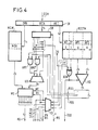
- FIG. 4 represents an embodiment of the routing circuit RL arranged for use in the elementary switch ISE of FIG. 1, and also allowing bidirectional operation in accordance with what is illustrated in FIG. 3.
- the circuits of FIG. 4 receive, in an IR register, the cell label CCH mentioned in FIG. 1, to provide as output the information marking the control link RMD which supplies the logic for managing cells and selecting outputs information specifying the selected routing mode (AS, MC, DI, ES, PH), as well as routing data (RG, PO)
- the circuits of FIG. 4 also receive, depending on the input on which a received cell arrived, an incoming direction indicator IO which is for example provided by the reception circuit supplying the cell in question, on the multiplexer entry of Figure 1, specifying the incoming direction concerned, in the sense mentioned with reference to Figure 3.
- an incoming direction indicator IO which is for example provided by the reception circuit supplying the cell in question, on the multiplexer entry of Figure 1, specifying the incoming direction concerned, in the sense mentioned with reference to Figure 3.
- the logical routing circuits of FIG. 4 operate as explained below, when the header of a received cell is present on the input multiplexer (FIG. 1), the label CCH of which is supplied to the register IR, while the IO bit indicates the incoming direction of routing. As indicated above, a rhythm clock the operation of the circuits, in an appropriate manner, in accordance with current practice in the matter.
- the RCC command information characteristic of a transfer sequence through the switching network, does not directly indicate the routing mode to be applied in the elementary exchange considered. This routing mode depends on the type of switching network and the position of the basic switch in it.
- control information to be interpreted, is used as the address for reading, in the command translation memory RCCTM, the routing parameters comprising the elements MT, EF, RPI and RPO defined above.
- the routing mode code to be applied MT is decoded by the routing mode decoder TD which, accordingly, provides one of the mode signals RS, MC, ES, DI or PH.
- the incoming direction indicator IO is applied to one of the inputs of the XOR exclusive OR gate, while the reflection bit EF is applied to its other input.
- the output of the XOR port provides the control signal for the outgoing direction selector RD.
- the latter selects either the "incoming" RPI routing group field or the "outgoing" RPO routing group field, specifying, for both sets of outputs, a specific part of the address RCA destination intended to provide the identity of a routing group on an output of which the received cell must be retransmitted.
- Each of these fields includes a 4-bit POS position indicator and a two-bit RGS dimension indicator.
- the position indicator POS controls the shift register SR so that the RCA information is shifted there and that a part of three bits which it contains comes in the three stages on the left, in the figure, of this register SR , or even that a part of five bits which it contains comes in the five left floors, in the figure, of the SR register.
- the RGS dimension indicator indicates how many of the three bits mentioned first should be used to define the identity of a routing group.
- the left bit of these three bits is transmitted directly from the shift register SR to the group number decoder GD, the next bit is transmitted by the AND gate AN1 conditioned by one of the signals RGS and the third bit by the AND gate AN2 conditioned by the other of the RGS signals.
- the group number decoder GD supplies an 8-bit word which constitutes the identity of a routing group, applied to the selector MS. In this word, only one bit is at 1, for example, all the others being at O.
- the internal 14-bit IRN broadcast tree reference number is applied by the IR register to the MCM broadcast memory, where it serves as the address for reading an 8-bit mask word MSK.
- this mask word identifies one or more routing groups in an 8-bit word, one or more of which is at 1, and the others at 0. It is also applied to the selector MS.
- the selector MS supplies at its output a group identity signal RG which is the signal supplied by the decoder GD; if it is the "broadcast” mode signal MC, the signal RG transmitted by the selector MS is the signal MSK.
- the five stages on the left of the shift register SR after the offset caused by the position indicator POS, directly provide the identity PO of an output to which the received cell must be retransmitted, in the case of the mode "physical" routing PH.
- the information contained in the command translation memory RCCTM defines, in each elementary switch, the interpretation that this switch must make of the 32 possible transfer sequences designated by the command information RCC to determine the mode d routing to apply routing data contained in the label of the received cell. This amounts to combining the routing information of a cell, unchanged while the cell crosses switches of different stages of the switching network, with the routing parameters of the switch, derived from its position in the network, for example its own on each floor and leading to a particular routing mode in each floor and for each routing sequence.
- the information contained in the RCCMT command translation memory is semi-permanent and can be entered when each elementary switch is put into service.
- the information contained in the broadcasting memory MCM must be modified during operation, for the establishment of each broadcasting tree.
- FIG. 4bis represents the general diagram of the cell management logic and selection of COQML output of FIG. 1.
- this circuit When the routing decision of a new cell received on an input of the elementary switch is taken by the routing circuit RL, this circuit provides the COQML logic with the routing mode information, as well as the data of associated routing, on the RMD command link, this command being validated by the signal FO command received from the SL circuit, which indicates the presence of a first FSC sub-cell containing the information intended for routing the cell during reception.
- the logic for managing sub-cell memories SBML provides the logic COQML with the WISA address of the buffer memory BM, in which this first sub-cell FSC has been recorded.
- the logic for managing memories of sub-cells SBML indicates a request for a next cell by means of the signal L then active, as explained previously, in the description of the SBML logic. Then, the COQML logic selects the next cell to be transmitted on this output, by supplying the SBML logic with the FSAO address of the first FSC sub-cell of the cell to be transmitted on the output YJ, this latter indication being notified by the YS output address also supplied by the COQML logic to the SBML logic, in order to be able to carry out this operation outside the synchronous clock time YJ relative to the output YJ.
- COQML logic In addition to managing the temporary waiting of cells to be transmitted, by sotocking their identities in queues, COQML logic also ensures the selection of an individual output in each selected routing group, given state only for the modes point-to-point routing RS, point-to-multipoint MC, and distribution DI, the routing circuit RL identifies only the routing groups to which a copy of the cell must be transmitted, or else the whole outputs in one direction in DI mode.
- this individual output selection function is performed by the QICL input control logic, before the identity of the cell is queued.
- each queue BQ1 / BQZ is directly associated with each of the Y outputs of the elementary switch.
- each queue BQ1 / BQZ is associated with a routing group comprising one or more outputs and not with an individual output of the elementary switch.
- the output selection device necessary for the RS, MC and DI routing modes can be produced in a known manner on the basis of a cyclic distribution of the cells at the outputs of a routing group considered, which makes it possible to achieve a homogeneous distribution of the traffic load of cells of the routing group on each of its outputs.
- Another proposed solution is to use a pseudo or quasi-random signal generator to select an output for each cell, which eliminates, at least in large part, any correlation between the fluxes of cells on the inputs and outputs of each elementary switch.
- an output of the elementary switch is respectively implicit or already selected and the role of the COQML logic is limited to the function of managing these cells in queues by corresponding individual output.
- FIGS. 5 to 12 give several examples of embodiment of the switching network of the invention, based on FIGS. 1 to 4, as regards the specific characteristics of the elementary switches employed in the different stages of these switching networks.
- the properties of a switching network come from the properties of the elementary switches which constitute it, as they are arranged, according to the invention, by the semi-permanent routing parameters derived from the position of the switches and from the configuration of the switching network, essentially comprising the number of stages, the unidirectional or bidirectional characteristic of each stage, the mesh between the elementary switches and the mode of connection of the input and output ports.
- the invention applies in all the configurations of switching networks which will be described, as well as in the numerous variants which can easily be deduced therefrom.
- FIG. 5 represents a switching network RC1, unidirectional and symmetrical, consisting of elementary switches such as that of FIG. 1, arranged in three stages comprising, the first, switches TSi1 to TSiT, having n inputs each, the central stage , switches AS1 to ASk, and the last, switches TSo1 to TSoT having n outputs each.
- Cell traffic is routed from the ingress ports to the egress ports by crossing all switches in one direction; this is why this network is said to be unidirectional.
- the T switches of the first stage have one or more (m) meshes towards each of the k switches of the central stage, ie mxk outputs.
- the T switches of the last stage have one or more (m) meshes coming from each of the switches of the central stage, ie mxk inputs.
- the switches of the central stage thus have Txm inputs and Txm outputs.
- Each of the switches of the central stage being able to reach all the switches of the last stage, a cell reaching the switching network on any input port, of the elementary switch TSi1, for example, can be addressed to any of the switches from the central floor, AS1 to ASk, that the routing of this cell either point-to-point or point-to-multipoint.
- provision will therefore be made, according to the invention, for the outputs of the first stage switches to be arranged in a single group of outputs and for a cell received by a first stage switch to be point-to-point. point or point to multipoint, will be retransmitted on an output selected in this unique group of outputs. It suffices for this (see description relating to FIG.
- a position data item included in the switches of the first stage (implicitly represented by the routing parameters contained in the command translation memory) will allow an interpretation in this sense of the routing information of the cell.
- each one of them has only one or more (m) meshes towards each switch of the last stage.
- the routing depends on the identity of the recipient exit.
- a group of one or more (m) meshes is accessible for this purpose.
- Each central stage switch will thus have T groups of one or m outputs. With a different position data, these switches will interpret the same cell routing information, so as to select the appropriate routing group, in the case of point-to-point routing, or the appropriate groups in the case of 'a point-to-multipoint routing of interesting outputs from several different elementary switches of the last stage.
- the RCC control information considered above will be translated, in these elementary switches of the central stage, into a "group” RS mode signal, for point-to-point routing, or into an "MC” mode signal, for point-to-point routing multipoint, while the RCA output address, or the IRN internal reference number, will be used to identify the selected group or groups of outputs.
- the switches of the central stage have two meshes with each of the switches of the first and of the last stage.
- the elementary switches of the central stage will have T groups of two outputs between which it will be necessary to make a selection.
- the number of elementary switches of the central stage can, according to another variant, be greater than that of the switches of the two extreme stages, all other things being equal. This will reduce the traffic load on the internal mesh of the switching network.
- the central stage could include 64 elementary switches, and, correlatively, the switches of the two extreme stages would have 128 outputs or inputs.
- the symmetrical unidirectional switching network of FIG. 6 comprises 4 stages.
- the designations of the elementary switches of the two extreme stages are the same as in FIG. 5.
- the elementary switches of the two central stages are respectively referenced ASi1 to ASik and ASo1 to ASok.
- the elementary switches of the first two stages form an input selection unit USi, while the elementary switches of the last two stages form an output selection unit USo. These two selection units are coupled to each other by meshes joining the homologous outputs and inputs.
- the elementary switches ASi1 to ASik will advantageously be arranged to operate a distribution, whether the routing mode is point to point or point to multipoint.
- the switches ASo1 to ASok, for their part, from the point of view of the control, will be treated like the elementary switches AS1 to ASk of FIG. 5.
- the switching network of FIG. 7 is similar to that of FIG. 6, but folded, therefore bidirectional, confusing the elementary switches of the extreme stages, TSi1 to TSiT and TSo1 to TSoT, into switches of the first stage TS1 to TST, while the designation of the switches of the second stage of FIG. 5, AS1 to ASk, for the elementary switches of the second stage of FIG. 7.
- the inputs of the first stage switches are shared between the input ports and the output ports of the connection network (by halves for a network without expansion / concentration).
- the internal meshes are double, comprising one or more connections for each direction of routing.
- the switches are bidirectional and they accomplish the reflection, either in the first stage, or in the second stage.
- the switch TS1 In the routing of a cell from an input of the elementary switch TS1 to one or more outputs of another switch TST, whether within the framework of point-to-point or point-to-multipoint routing, the switch TS1 distributes to all of the switches in the next stage, while that of the switches in the second stage which routes the cell applies the "group" or "broadcast” routing mode and the same applies to as regards the basic switch TST.
- a transfer reflection can be carried out directly at the level of the first stage, that is to say in the bidirectional switch TS1 which transfers the cell directly to the destination (s), instead of transferring it normally for distribution to the next floor.
- FIG. 8 represents a switching network derived from that of FIG. 5, but here obtained by juxtaposition of two separate unidirectional switching networks which are homologous stage by stage, each allowing the transfer in a given direction, of the N1 inputs on one side to the N2 outputs on the other side, or N2 inputs on the latter side to the N1 outputs on the first side.
- a switching network can typically be used to constitute an asymmetrical assembly interconnecting N1 bidirectional link on one side to N2 bidirectional link of the other side, with N1> N2.
- the unidirectional network from N1 to N2 therefore achieves a concentration of traffic and the other unidirectional network from N2 to N1 an expansion of traffic.
- Each of these unidirectional networks therefore differs from that of FIG. 1 only in that it is asymmetrical due to the presence of at least one stage of asymmetrical elementary switches, that is to say of which the numbers d 'inputs and outputs are different, for example 32x16 or 16x32.
- the routing principles described for each stage of the network in FIG. 5 remain applicable to the corresponding stages in each of these two asymmetrical unidirectional networks.
- FIG. 9 represents an equivalent of the switching network of FIG. 8, in a bidirectional configuration.
- the asymmetric switching network interconnects the N1 input and output ports on one side to the N2 input and output ports on the other side.
- N1> N2 such a network is typically applied to the concentration of N1 links with relatively low traffic to N2 links with higher traffic.
- Cell transfers can therefore be carried out between these two sets of ports N1 and N2, ie unidirectional, from an input port of the set N1 (or N2) to an output port of the set N2 (or N1 ), or bidirectional between an input and output port of the N1 assembly and an input and output port of the N2 assembly.
- the presence of at least one bidirectional stage also makes it possible to transfer cells between an input port and an output port of the same assembly N1 (or N2), by carrying out a reflection in a bidirectional stage.
- the dimensioning of this network is similar to that of FIG. 8; as in the latter, at least one of the stages is asymmetrical, so that the switching network has different numbers of input and output ports N1 and N2 on either side of the switching network.
- FIG. 10 represents a possible extension of the switching network of FIG. 9 by adding an additional selection stage.
- the first two stages of switches on the side of all the N1 input and output ports, are formed into m two-stage selection units, with bidirectional routing, each similar, except for the dimensioning, to the network. of FIG. 7, the elementary switches being moreover identified by the same references as in this latter figure.
- This example of a switching network illustrates once again the fact that, according to the invention, the output groups formed in the switches of the switching network are not the same depending on the stage to which they belong and that they are required to do so. counts in the routing mode implemented, at the level of each stage, although the routing information of the cell remains the same in all the stages.
- FIG. 11 represents a unidirectional switching network composed of selection units which include input terminal units TSUi, selection planes PS and output terminal units TSUo.
- each selection unit there are elementary switches which can be of the type of the preceding figures, each represented by the usual sign of a switching matrix, with, on the left, the number of the inputs of the elementary switch and, on the right, the number of its outputs. These elementary switches are interconnected by meshes.
- I1 generally exists one or more meshes between an output of an elementary switch of the first stage and an input of an elementary switch of the second stage.
- the four outputs of a first stage switch, TSi1 for example, are then each connected to one or more inputs of each of the four elementary switches of the second stage.
- the 16 inputs of an elementary switch of the second stage, ASi1 for example are each connected to an output of each of the 16 elementary switches of the first stage.
- the 16 times 4 inputs of the first stage elementary switches are connected to 64 input ports pi1 to pi64.
- the other input terminal units may be similar, except for the numerical values shown.
- the output terminal units are assumed to be arranged in the same way and symmetrically.
- the output terminal unit TSUo1 gives access, by the two stages of elementary switches comprising the elementary switches ASo1 to ASo4 and TSo1 to TSo16, to output ports po1 to po64.
- the figure also shows TSUi128 and TSUo128 input and output terminal units, to indicate a total number of terminal units in the switching network.
- the selection planes such as the selection plan PS1, comprise three selection stages formed by the elementary switches PSi1 to PSi32, PSc1 to PSc16, PSo1 to PSo32.
- the arrangement of the internal meshes between a stage and the following one obeys the principle of that of the terminal selection units, by supposing in this example a number of meshes between switches equal to one; we will not describe it in detail.
- the 16 outputs of a second stage switch of an input terminal selection unit, TSUi1 for example, are individually connected, by 16 meshes, to an input of each of the 16 selection plans.
- the 4 outputs of the same rank of the four elementary switches of an input terminal unit, TSUi1 for example, are connected to successive inputs of the same elementary switch, PSi1, for example of a selection plane, PS1 in l 'occurrence. Therefore, the 512 inputs of a selection plan, PS1 for example, are connected, four by four, to the four elementary switches of the second stage of each of the 128 input terminal units.
- each central elementary switch such as PSc1
- PSc1 is connected, by three switching stages, on each side, to all input ports and to all output ports.
- any input port and any output port there are in this example more than 4000 (4 k) separate paths passing through one of the four switches ASi of the incoming selection unit, one of the 16 selection planes PS, one of the 16 central switches PSc in a plan, and one of the four switches ASo of the outgoing selection unit.
- the transfer in this first part of the network achieves a generalized distribution of all incoming traffic on all 16x16 central PSc switches, therefore a complete mixing of all cell traffic incoming.
- the routing is necessarily selective, in order to reach the destination output port or ports. If it is a question of reaching several distinct output ports, in a point-to-multipoint routing, this selective routing must include several branches with one or more stages.
- a routing mode data item of the RCC command field specifies point-to-point routing.
- the RCA output address comprises 7 bits designating the terminal unit TSUo1 and 6 bits designating the output port po1 in the terminal unit.
- the routing parameters are such that the cell is retransmitted on one of the set of all the outputs of the elementary switch. We have seen the conditions of this selection previously. For example, the cell is thus retransmitted towards the elementary switch ASi1.
- the routing parameters have the same effect as in the first stage and the cell is thus retransmitted on one of the set of all the outputs of the switch elementary, for example that which leads to the plane PS1 and therefore, therein, to the elementary switch PSi1.
- the routing becomes selective, at least in part.
- the routing parameters of the switches in the central stage of the switching network are such that the switch PSc1 selects a group of four terminal units in which the destination terminal unit is located, on the basis of 5 bits, among the 7 bits for designation of the terminal selection unit, which designate the routing group, in the present example a single output, leading to that of the 32 elementary switches of the fourth stage of the switching network which, in the plane PS1, accesses the destination terminal unit. Thus a mesh is selected leading to the elementary switch PSo1.
- the operating mode is similar to that which we have just seen, in the elementary switches of the fifth stage of the switching network.
- the routing parameters are different; they cause the selection of the 2 remaining bits of the identity of the destination terminal unit, which identifies a routing group comprising the four outputs leading to the four elementary switches ASo1 to ASo4, according to the example considered.
- One of these four outputs is selected in the manner mentioned above. It leads the cell, for example, to the ASo1 switch.
- the routing parameters select, from the 6 bits of the RCA address designating the output port, the 4 bits identifying the switch elementary of the top floor serving this exit port.
- the cell is thus led to the elementary switch TSo1, in accordance with the example chosen.
- the routing parameters will allow the cell to be transferred to the output port po1.
- successive cells from the same source and with the same destination can, mainly thanks to the routing routing practiced in the first stages of the switching network, take a large number of different paths, which achieves a mixing of regular and irregular traffic currents, favorable to the more homogeneous flow of the rates of various cells subjected to the switching network and therefore to the relative performance of cell transfer.
- Point-to-multipoint routing in such a network is carried out on the same bases, except that in some or all stages with selective routing, there is a multiplication of the cell with retransmission on groups of Different outputs in the floor switches where the diffusion tree indicates that several outgoing branches are required to the next floor.
- the central stage PSc remains unidirectional and this fourth stage is called the mirror stage (compulsory reflection).
Landscapes
- Engineering & Computer Science (AREA)
- Computer Networks & Wireless Communication (AREA)
- Signal Processing (AREA)
- Physics & Mathematics (AREA)
- Mathematical Physics (AREA)
- Data Exchanges In Wide-Area Networks (AREA)
Abstract
Description
La présente invention concerne un réseau de commutation à trajets multiples et à auto-acheminement pour la commutation de cellules à multiplexage temporel asynchrone.The present invention relates to a self-routing multipath switching network for switching cells with asynchronous time multiplexing.
Un réseau de commutation, dans sa définition structurelle la plus large comprend des ports d'entrée auxquels sont connectées des liaisons d'entrée, des ports de sortie auxquels sont connectées des liaisons de sortie, des commutateur élémentaires disposés entre ces ports d'entrée et ces ports de sortie, arrangés en un ou plusieurs étages et interconnectés par des mailles. Les ports d'entrée du réseau de commutation sont associés aux entrées de commutateurs élémentaires d'un premier étage, tandis que les ports de sortie sont associés aux sorties de commutateur élémentaires d'un dernier étage. Les sorties des commutateurs élémentaires dudit premier étage sont couplées par des mailles, éventuellement au moyen d'étages intermédiaires de commutateurs élémentaires, aux entrées des commutateurs élémentaires dudit dernier étage. Les mailles, d'une manière générale, comprennent une ou plusieurs liaisons autonomes, connectant chacune une sortie d'un commutateur à une entrée d'une autre commutateur, ou du même.A switching network, in its broadest structural definition includes input ports to which input links are connected, output ports to which output links are connected, elementary switches arranged between these input ports and these output ports, arranged in one or more stages and interconnected by meshes. The input ports of the switching network are associated with the elementary switch inputs of a first stage, while the output ports are associated with the elementary switch outputs of a last stage. The outputs of the elementary switches of said first stage are coupled by meshes, possibly by means of intermediate stages of elementary switches, to the inputs of the elementary switches of said last stage. The meshes, in general, include one or more autonomous links, each connecting an output of a switch to an input of another switch, or the same.
Un tel réseau de commutation est dit à trajets multiples lorsqu'il offre plus d'un trajet de commutation entre un port d'entrée et un port de sortie quelconques. Dans ce cas, la désignation d'un port d'entrée et d'un port de sortie n'est pas suffisante pour déterminer un trajet allant de l'un à l'autre. Il reste encore un choix à effectuer entre les multiples trajets qu'offre le réseau de commutation entre ce port d'entrée et ce port de sortie.Such a switching network is said to be multipath when it offers more than one switching path between any input port and any output port. In this case, the designation of an input port and an output port is not sufficient to determine a path going from one to the other. There is still a choice to be made between the multiple paths offered by the switching network between this input port and this output port.
Un tel réseau est encore dit à auto-acheminement, au sens large du terme, lorsqu'il est tel que la détermination d'un trajet de commutation se fait, dans le réseau de commutation, non seulement à l'aide d'une information d'acheminement contenant la désignation implicite ou explicite d'un port d'entrée et celle d'un port de sortie du réseau de commutation, mais aussi par une décision d'acheminement propre au réseau de commutation.Such a network is also said to be self-routing, in the broad sense of the term, when it is such that the determination of a switching path is made, in the switching network, not only using information routing containing the implicit or explicit designation of an input port and that of an output port of the switching network, but also by a routing decision specific to the switching network.
La faculté d'auto-acheminement introduite dans le réseau de commutation fournit ainsi un moyen autonome pour résoudre le problème d'acheminement que posent les réseaux à trajets multiples, lorsque l'acheminement est seulement défini par la désignation d'un port d'entrée et d'un port de sortie.The auto-routing capability introduced into the switching network thus provides an autonomous means for solving the routing problem posed by multipath networks, when routing is only defined by the designation of an input port. and an output port.
Des réseaux de commutation à trajets multiples et à auto-acheminement par connexion sont bien connus dans la commutation de circuits ou la commutation de voies à multiplexage temporel synchrone. Le processus d'acheminement ou d'établissement de connexion y est accompli une fois, au début d'une communication, et détermine un trajet de commutation dont les éléments, initialement libres, sont ensuite occupés par la communication, et deviennent donc indisponibles pour les autres communications. Les trajets de commutation établis causent donc un risque de blocage par manque de voies dans la recherche de tout nouveau trajet de commutation. Le processus de commutation appliqué dans ces réseaux de commutation connus embrasse généralement l'ensemble ou une partie importante du réseau de commutation. Il est par conséquent complexe et requiert un laps de temps relativement important, en terme d'opérations élémentaires de commande pour établir la connexion. Par contre, ce laps de temps est très court, comparé à la durée de la communication et n'est donc pas préjudiciable, en ce qui concerne l'efficacité de communication du réseau de commutation.Multipath switching and connection auto-routing networks are well known in circuit switching or synchronous time division multiplex switching. The routing or connection establishment process is accomplished there once, at the start of a communication, and determines a switching path whose elements, initially free, are then occupied by the communication, and therefore become unavailable for calls. other communications. The established switching paths therefore cause a risk of blockage due to lack of channels in the search for any new switching path. The switching process applied in these known switching networks generally embraces the whole or a significant part of the switching network. It is therefore complex and requires a relatively long period of time, in terms of elementary control operations to establish the connection. On the other hand, this period of time is very short, compared to the duration of the communication and is therefore not detrimental, as regards the communication efficiency of the switching network.
Les cellules, aussi appelées paquets, sont des unités d'information numérique comprenant notamment une étiquette contenant une information permettant d'identifier la destination de la cellule, ainsi que des données de communication.Cells, also called packets, are units digital information including a label containing information to identify the destination of the cell, as well as communication data.
Les cellules sont soit de longueur fixe, soit de longueur variable. Dans le dernier cas, la cellule est transférée sous forme d'une séquence ininterrompue d'un certain nombre de sous-cellules de longueur fixe de taille relativement petite, ce qui permet d'optimiser le transfert interne, le stockage en mémoire ou dans les registres, et les fonctions de traitement au niveau des sous-cellules.The cells are either of fixed length or of variable length. In the latter case, the cell is transferred in the form of an uninterrupted sequence of a certain number of sub-cells of fixed length of relatively small size, which makes it possible to optimize the internal transfer, the storage in memory or in the registers, and processing functions at the sub-cell level.
Dans un système de transmission de cellules à multiplexage temporel asynchrone, les cellules de plusieurs communications, transmises sur une même liaison, se suivent dans un ordre quelconque et des cellules relatives à une même communication sont transmises à intervalles irréguliers.In an asynchronous time division multiplex cell transmission system, the cells of several communications, transmitted on the same link, follow each other in any order and cells relating to the same communication are transmitted at irregular intervals.
Compte tenu des caractéristiques de la transmission de cellules à multiplexage temporel asynchrone, un réseau de commutation de cellules à multiplexage temporel asynchrone est généralement un réseau de commutation agencé pour commuter individuellement de telles cellules, de telle sorte qu'un trajet de commutation soit recherché pour chacune d'elles, pour l'acheminer d'un port d'entrée du réseau jusqu'à un port de sortie au moins. Dans ce cas, un réseau de commutation "à auto-acheminement par cellule" permet d'affectuer une recherche et une sélection de trajet pour chaque cellule individuelle. En outre, il est aussi communément admis que, dans ce type de réseau, il y a lieu de prévoir, non seulement l'acheminement classique, dit de point à point, d'un port d'entrée à un port de sortie, mais aussi au moins l'acheminement dit de point à multipoint, entre un port d'entrée et plusieurs ports de sortie.In view of the characteristics of transmission of asynchronous time-division multiplex cells, a switching network of asynchronous time-division multiplex cells is generally a switching network arranged to switch such cells individually, so that a switching path is sought for each of them, to route it from a network input port to at least one output port. In this case, a "self-routing by cell" switching network makes it possible to search and select a path for each individual cell. In addition, it is also commonly accepted that, in this type of network, provision should be made not only for conventional routing, said to be point-to-point, from an input port to an output port, but also at least the so-called point-to-multipoint routing, between an input port and several output ports.
Cependant, un processus d'établissement préalable de connexion, tel que celui que l'on vient d'évoquer pour les réseaux de commutation de circuits ou de voies à multiplexage temporel synchrone, s'il est en principe également applicable à la commutation de cellules à multiplexage temporel asynchrone, présente toutefois un certain nombre d'inconvénients, tel que la complexité de la gestion des débits des connexions établies sur chaque maille interne du réseau et un laps de temps trop important pour établir des connexions de données.However, a prior connection establishment process, such as that just mentioned for circuit switching networks or multiplexing channels synchronous temporal, if it is in principle also applicable to the switching of cells with asynchronous temporal multiplexing, however presents a certain number of disadvantages, such as the complexity of the management of the bit rates of the connections established on each internal mesh of the network and a too long to establish data connections.
Les réseaux de commutation à trajets multiples et à auto-acheminement par connexion connus dans la commutation de circuits ou la commutation de voies à multiplexage temporel synchrone ne constituent donc pas une solution optimale pour la commutation de cellules à multiplexage temporel asynchrone. La technique s'est donc tournée vers des réseaux de commutation spécifiques dans lesquels le processus de commutation y compris la recherche de trajet a lieu étage par étage pour chaque cellule individuelle, donc sans établissement et marquage préalable de connexion au début de la communication.Multipath switching networks with connection auto-routing known in circuit switching or synchronous time multiplex switching are therefore not an optimal solution for switching cells with asynchronous time multiplexing. The technique has therefore turned to specific switching networks in which the switching process including the path search takes place floor by floor for each individual cell, therefore without establishing and marking prior connection at the start of the communication.
On trouvera la description d'un exemple de réseau de commutation de ce type dans l'article "Design of a Broadcast Packet Network", de J.S. Turner, publié dans les "Proceedings of IEEE INFOCOM'86", Fifth Annual Conference, "Computers and Communications Integration Design, Analysis, Management", pages 668 à 673.A description of an example of such a switching network can be found in the article "Design of a Broadcast Packet Network", by JS Turner, published in "Proceedings of IEEE INFOCOM'86", Fifth Annual Conference, "Computers and Communications Integration Design, Analysis, Management ", pages 668 to 673.
Un tel réseau comprend, de ports d'entrée à ports de sortie, des étages spécialisés dans la multiplication de cellules nécessaire pour les communications de point à multipoint, des étages spécialisés dans le brassage des cellules, pour mélanger les cellules provenant des différentes entrées et obtenir des débits moyens par maille égaux et stables, autant qu'il est statistiquement possible, et des étages spécialisés dans l'acheminement sélectif vers les ports de sortie. Ce réseau est construit à l'aide de commutateurs élémentaires à deux entrées et deux sorties seulement. Une petite mémoire tampon pour deux cellules est prévue à chaque entrée du commutateur élémentaire. Lorsqu'une cellule doit emprunter une sortie qui n'est pas disponible, parce qu'une autre cellule est alors retransmise sur cette sortie, l'entrée peut conserver temporairement la cellule non retransmise.Such a network comprises, from input ports to output ports, stages specialized in the multiplication of cells necessary for point-to-multipoint communications, stages specialized in the mixing of cells, for mixing the cells coming from the different inputs and obtain equal and stable average throughputs per mesh, as far as statistically possible, and stages specializing in selective routing to the output ports. This network is built using elementary switches with two inputs and two outputs only. A small buffer for two cells is provided at each input of the basic switch. When a cell must take an exit which is not available, because another cell is then retransmitted on this exit, the entry can temporarily keep the cell not retransmitted.
Un tel réseau possède des inconvénients et limitations tels que, notamment :
- un grand nombre d'étages, lorsque le nombre de ports d'entrée et de sortie est élevé,
- une efficacité limitée par la rétention des cellules aux entrées en cas d'occupation des sorties,
- une certaine difficulté dans la réalisation d'extensions, due entre autres au grand nombre d'étages,
- l'existence d'étages de multiplication de cellules, causant un coût additionnel,
- une certaine sensibilité au processus d'arrivée des cellules sur chaque port d'entrée, qui n'est pas complètement maîtrisée par l'emploi d'étages de brassage et qui affecte donc les performances du réseau de commutation, etc.
- a large number of stages, when the number of input and output ports is high,
- an efficiency limited by the retention of cells at the entrances in the event of occupation of the exits,
- a certain difficulty in the realization of extensions, due inter alia to the large number of stages,
- the existence of cell multiplication stages, causing an additional cost,
- a certain sensitivity to the process of arrival of cells at each input port, which is not completely controlled by the use of patch stages and which therefore affects the performance of the switching network, etc.
La présente invention a pour objet un réseau de commutation de cellules à multiplexage temporel asynchrone à auto-acheminement par cellule ne souffrant pas, ou tout au moins ne souffrant que dans un bien plus faible mesure, des inconvénients et limitations sus-mentionnés.The subject of the present invention is a self-routing asynchronous time-division multiplex cell switching network per cell not suffering, or at least suffering only to a much lesser extent, from the above-mentioned drawbacks and limitations.
Le réseau de commutation de la présente invention se caractérise en ce que :
- chaque commutateur d'un étage au moins du réseau possède au moins trois sorties,
- ces sorties sont arrangées en groupes de sorties dits groupes d'acheminement,
- un groupe de sorties comprend une ou plusieurs sorties déterminées,
- en fonction d'informations d'acheminement associées à une cellule de longueur fixe ou variable reçue sur l'une quelconque de ses entrées, le commutateur est agencé pour identifier un ensemble comprenant un ou plusieurs desdits groupes de sorties, une copie de la cellule étant transférée vers chacun des groupes de sorties identifiés,
- le commutateur est agencé pour transférer ladite cellule reçue, sur une sortie sélectionnée parmi les sorties du groupe unique dudit ensemble, ou des sorties, une par groupe dudit ensemble, chacune sélectionnée parmi les sorties du groupe auquel elle appartient.
- each switch of at least one stage of the network has at least three outputs,
- these outputs are arranged in groups of outputs called routing groups,
- a group of outputs includes one or more specific outputs,
- based on routing information associated with a cell of fixed or variable length received on one any of its inputs, the switch is arranged to identify a set comprising one or more of said output groups, a copy of the cell being transferred to each of the identified output groups,
- the switch is arranged to transfer said received cell, to an output selected from the outputs of the single group of said set, or outputs, one per group of said set, each selected from the outputs of the group to which it belongs.
Ce réseau est donc composé, dans un de ses étages au moins, de commutateurs élémentaires qui, par la constitution de groupes de sorties déterminées, entre lesquelles à chaque fois une sortie est sélectionnée, procurent non seulement un acheminement sélectif, mais apportent aussi un brassage des cellules par répartition de celles-ci sur les différentes sorties d'un groupe d'acheminement. De plus, l'acheminement possible sur une sortie de chacun de plusieurs groupes réalise la multiplication de cellules nécessaires dans le cas d'acheminement de point à multipoint. Ainsi, comme il apparaîtra plus loin, un tel commutateur se prête à la réalisation de réseaux de commutation intégrés dans lesquels la spécialisation de parties du réseau de commutation disparaît. Plus le commutateur élémentaire comprend de sorties par groupe, mieux se réalise le brassage, car plus grand est le nombre de trajets offerts à une cellule, ce qui tend également à réduire le blocage par manque de sortie disponible, ou à augmenter l'efficacité d'acheminement du commutateur élémentaire et donc de l'ensemble de réseau de commutation. De même, le commutateur élémentaire est alors moins sensible au processus d'arrivée des cellules, puisque les cellules d'une même entrée sont acheminées par une multiplicité de trajets différents à chaque étage.This network is therefore composed, in at least one of its stages, of elementary switches which, by the constitution of groups of determined outputs, between which each time an output is selected, not only provide a selective routing, but also bring a mixing cells by distribution of these on the different outputs of a routing group. In addition, the possible routing on an output of each of several groups achieves the multiplication of cells necessary in the case of point-to-multipoint routing. Thus, as will appear below, such a switch lends itself to the realization of integrated switching networks in which the specialization of parts of the switching network disappears. The more the basic switch includes outputs per group, the better the shuffling is carried out, because the greater the number of paths offered to a cell, which also tends to reduce blocking due to lack of available output, or to increase the efficiency of routing of the elementary switch and therefore of the entire switching network. Similarly, the elementary switch is then less sensitive to the process of arrival of the cells, since the cells of the same input are routed by a multiplicity of different paths to each stage.
Dans un réseau de commutation à plusieurs étages, on pourra prévoir que les commutateurs élémentaires de deux étages au moins possèdent les caractéristiques indiquées ; l'arrangement des sorties en groupes n'est alors pas nécessairement le même dans chacun des ces deux étages au moins et les commutateurs de chacun de ces étages sont agencés pour détenir chacun des paramètres d'acheminement propres dérivés d'une donnée de position.In a multistage switching network, provision may be made for elementary switches of at least two stages to have the characteristics indicated; the arrangement of the outputs in groups is then not necessarily the same in each of these two stages at least and the switches of each of these stages are arranged to hold each of the own routing parameters derived from a position datum.
De telles dispositions permettront de tenir compte de l'emplacement respectif des commutateurs élémentaires, dans le réseau de commutation, dans l'arrangement de leurs sorties en groupes et notamment du fait que le maillage entre des paires d'étages successifs n'est pas nécessairement le même.Such arrangements will make it possible to take account of the respective location of the elementary switches, in the switching network, in the arrangement of their outputs in groups and in particular of the fact that the mesh between pairs of successive stages is not necessarily the same.
Selon une autre caractéristique de l'invention, lesdites informations d'acheminement sont interprétées dans chaque étage pour déterminer le mode de transfert d'une cellule reçue vers les sorties du commutateur élémentaire, et ladite interprétation s'effectue en fonction desdits paramètresd'acheminement dérivés de sa position.According to another characteristic of the invention, said routing information is interpreted in each stage to determine the mode of transfer of a received cell to the outputs of the elementary switch, and said interpretation is carried out as a function of said derived routing parameters from its position.
Ces dispositions permettent d'utiliser le même type de commutateur dans les différents étages d'un réseau de commutation et d'employer un unique ensemble d'informations d'acheminement dans une cellule et néanmoins d'obtenir différents modes de transfert de la cellule dans les différents étages du réseau de commutation, ce qui apporte une grande souplesse dans l'emploi des différents modes d'acheminement pour transférer une cellule à travers le réseau de commutation selon une variaté de séquences de transfert possible.These provisions make it possible to use the same type of switch in the different stages of a switching network and to use a single set of routing information in a cell and nevertheless to obtain different modes of transfer from the cell in the different stages of the switching network, which provides great flexibility in the use of the different routing modes for transferring a cell through the switching network according to a variety of possible transfer sequences.
Dans un mode d'application particulièrement avantageux, les commutateurs de certains étages du réseau au moins comprennent des moyens pour interpréter des informations d'acheminement, contenues dans une étiquette d'acheminement d'une cellule, qui comprennent un code de commande d'acheminement (RCC) définissant la séquence de transfert requise pour la cellule, une adresse de port de sortie (RCA), pour un acheminement de point à point, et/ou d'un numéro de référence interne d'arbre de diffusion (IRN), pour un acheminement de point à multipoint.In a particularly advantageous application mode, the switches of at least certain stages of the network include means for interpreting routing information, contained in a routing label of a cell, which includes a routing control code (RCC) defining the transfer sequence required for the cell, an output port address (RCA), for point-to-point routing, and / or an internal broadcast tree reference number (IRN), for point-to-multipoint routing.
Les commutateurs considérés, interprétant ledit code de commande d'acheminement en fonction desdits paramètres d'acheminement dérivés de sa position, sont prévus pour mettre en oeuvre en conséquence un mode d'acheminement qui peut être, entre autres, un acheminement de point à point ou un acheminement de point à multipoint.The switches under consideration, interpreting said routing control code as a function of said routing parameters derived from its position, are provided to consequently implement a routing mode which can be, inter alia, point-to-point routing or point-to-multipoint routing.
L'invention comprend le cas où les commutateurs élémentaires de tous les étages sont symétriques, ayant le même nombre d'entrées et de sorties, et où le réseau de commutation est par suite également symétrique, ayant le même nombre de ports d'entrée et de ports de sortie.The invention includes the case where the elementary switches of all the stages are symmetrical, having the same number of inputs and outputs, and where the switching network is consequently also symmetrical, having the same number of input ports and output ports.
Selon une autre caractéristique de l'invention, les commutateurs élémentaires d'un étage au moins peuvent être dissymétriques et réaliser chacun une expansion de trafic entrant, réduisant la charge de trafic de cellules des sorties de ces commutateurs par rapport à leurs entrées.According to another characteristic of the invention, the elementary switches of at least one stage can be asymmetrical and each achieve an expansion of incoming traffic, reducing the traffic load of cells of the outputs of these switches compared to their inputs.
De telles dispositions permettent de réduire la charge des sorties des commutateurs et donc la rétention des cellules ou leur perte dans les commutateurs élémentaires, ou les besoins correspondants en mémoire tampon dans ces commutateurs élémentaires.Such arrangements make it possible to reduce the load on the outputs of the switches and therefore the retention of the cells or their loss in the elementary switches, or the corresponding buffer memory requirements in these elementary switches.
Inversement, les commutateurs élémentaires d'un étage au moins peuvent être dissymétriques et réaliser chacun une concentration du trafic sortant en augmentant la charge de trafic de cellules des sorties de ces commutateurs par rapport à leurs entrées.Conversely, the basic switches of at least one stage can be asymmetrical and each achieve concentration of outgoing traffic by increasing the cell traffic load of the outputs of these switches relative to their inputs.
Chacun de ces deux types d'utilisation de commutateurs élémentaires dissymétriques dans un étage au moins permet de réaliser des réseaux de commutation dissymétriques, c'est-à-dire dont les nombres de ports d'entréeet de ports de sortie sont différents, dans le premier cas pour ventiler le trafic sur un plus grand nombre de ports de sortie et dans le second cas pour concentrer le trafic sur un plus petit nombre de ports de sortie.Each of these two types of use of asymmetrical elementary switches in at least one stage makes it possible to produce asymmetrical switching networks, that is to say the numbers of input ports and of output ports are different, in the first case to break down the traffic on a larger number of exit ports and in the second case to concentrate the traffic on fewer outbound ports.
En outre, l'utilisation conjuguée d'étages dissymétriques, mais de sens différents, dans un même réseau de commutation est également possible. En particulier, il est même possible de réaliser un réseau de commutation symétrique, ayant le même nombre de ports d'entrée et de ports de sortie, dans lequel un des premiers étages au moins est dissymétrique et réalise une expansion de trafic et un des derniers étages au moins est dissymétrique et réalise une concentration de trafic qui compense l'expansion préalable. On obtient alors, entre ces deux étages dissymétriques une réduction de la charge de trafic des mailles internes du réseai de commutation avec les avantages mentionnés plus haut.In addition, the combined use of asymmetrical stages, but of different directions, in the same switching network is also possible. In particular, it is even possible to realize a symmetrical switching network, having the same number of input ports and output ports, in which at least one of the first stages is asymmetrical and realizes an expansion of traffic and one of the last floors at least is asymmetrical and achieves a concentration of traffic which compensates for the prior expansion. There is then obtained, between these two asymmetrical stages, a reduction in the traffic load of the internal meshes of the switching network with the advantages mentioned above.
L'invention a également pour objet un réseau de commutation dans lesquels les commutateurs de certains des étages aux moins acheminent des cellules appartenant à deux courants de trafic opposés, et dans lequel, dans chacun de ces commutateurs dits commutateurs bidirectionnels, les entrées sont réparties en deux ensembles d'entrées et les sorties en deux ensembles de sorties, un courant de trafic étant normalement acheminé d'un premier ensemble d'entrées à un premier ensemble de sorties et l'autre courant de trafic d'un deuxième ensemble d'entrées à un deuxième ensemble de sorties ; l'interprétation des données d'acheminement dans lé commutateur élémentaire tient également compte de l'ensemble d'entrées auquel elles appartiennent pour déterminer si l'acheminement doit être "normal", c'est-à-dire vers l'ensemble de sorties associé (même courant de trafic) ou bien "réfléchi", c'est-à-dire vers l'autre ensemble de sorties (courant de trafic opposé).The invention also relates to a switching network in which the switches of some of the stages at least route cells belonging to two opposite traffic streams, and in which, in each of these switches called bidirectional switches, the inputs are distributed in two sets of inputs and outputs into two sets of outputs, one traffic stream normally being routed from a first set of inputs to a first set of outputs and the other traffic stream being from a second set of inputs to a second set of outputs; the interpretation of the routing data in the elementary switch also takes into account the set of inputs to which they belong to determine whether the routing should be "normal", that is to say to the set of outputs associated (same traffic flow) or "reflected", that is to say to the other set of exits (opposite traffic flow).
L'invention s'étend aussi toutefois au cas où les commutateurs élémentaires de tous les étages du réseau de commutation sont unidirectionnels, acheminant des cellules appartenant à un seul courant de trafic acheminés des entrées de chacun de ces commutateurs élémentaires à leurs sorties.The invention also extends however to the case where the elementary switches of all the stages of the switching network are unidirectional, conveying cells belonging to a single traffic stream routed from the inputs of each of these elementary switches at their outputs.
Selon une forme de réalisation de l'invention, le réseau de connexion comprend trois étages unidirectionnels au moins, chaque commutateur d'un étage, sauf le dernier, étant connecté par une ou plusieurs mailles à chaque commutateur de l'étage suivant et chaque commutateur d'un étage, sauf le premier, étant connecté par une ou plusieurs mailles à chaque commutateur de l'étage précédent.According to one embodiment of the invention, the connection network comprises at least three unidirectional stages, each switch of a stage, except the last, being connected by one or more meshes to each switch of the following stage and each switch of a stage, except the first, being connected by one or more meshes to each switch of the preceding stage.
Selon une autre forme de réalisation de l'invention, le réseau de commutation comprend au moins une unité de sélection d'entrée et au moins une unité de sélection de sortie, formées chacune de commutateurs élémentaires agencés en deux étages au moins et dans chacune desquelles chaque commutateur d'un étage, sauf le dernier, est connecté par une ou plusieurs mailles à chaque commutateur de l'étage suivant et chaque commutateur d'un étage, sauf le premier, est connecté par une ou plusieurs mailles à chaque commutateur de l'étage précédent, les unités de sélection d'entrée étant disposées en tandem avec les unités de sélection de sortie, les ports d'entrée étant connectés aux entrées des unités de sélection d'entrée et les ports de sortie aux sorties des unités de sélection de sortie.According to another embodiment of the invention, the switching network comprises at least one input selection unit and at least one output selection unit, each formed of elementary switches arranged in at least two stages and in each of which each switch of a stage, except the last, is connected by one or more meshes to each switch of the following stage and each switch of a stage, except the first, is connected by one or more meshes to each switch of l previous stage, the input selection units being arranged in tandem with the output selection units, the input ports being connected to the inputs of the input selection units and the output ports to the outputs of the selection units Release.
Dans cette dernière forme de réalisation, une seule unité de sélection d'entrée peut être connectée directement à une seule unité de sélection de sortie, par brassage entre les sorties de la première et les entrées de la seconde.In this latter embodiment, a single input selection unit can be connected directly to a single output selection unit, by mixing between the outputs of the first and the inputs of the second.
Dans le cas de plusieurs unités de sélection d'entrée et de sortie, selon l'invention, le réseau de commutation peut comprendre en outre des unités de sélection dites plans de sélection connectant chacune des sorties d'unité de sélection d'entrée à des entrées d'unité de sélection de sortie.In the case of several input and output selection units, according to the invention, the switching network can further comprise selection units called selection planes connecting each of the input selection unit outputs to output selection unit inputs.
Selon une autre caractéristique de l'invention, dans les commutateurs élémentaires d'un étage au moins, l'un desdits groupes de sorties d'un commutateur élémentaire comprend toutes les sorties du commutateur élémentaire, dans le cas d'un commutateur unidirectionnel, ou bien toutes les sorties de l'un des deux ensembles de sorties, pc une direction de transfert donnée, dans le cas d'un commutateur bidirectionnel, pour une distribution générale du trafic entrant sur toutes les sorties de ce commutateur élémentaire, dans la direction de transfert entrante..According to another characteristic of the invention, in the elementary switches of at least one stage, one of said groups of outputs of an elementary switch includes all the outputs of the elementary switch, in the case of a unidirectional switch, or all the outputs of one of the two sets of outputs, pc a given transfer direction, in the case of a bidirectional switch, for a general distribution of incoming traffic on all the outputs of this basic exchange, in the incoming transfer direction.
Selon une autre forme de réalisation de l'invention, le réseau de commutation est configuré en réseau replié extensible, possédant au moins deux étages dont l'un au moins est bidirectionnel, les ports d'entrée étant connectés aux entrées dudit premier ensemble d'entrées des commutateurs élémentaires d'un premier étage et les ports de sortie étant connectés aux sorties dudit deuxième ensemble de sorties de ces mêmes commutateurs élémentaires du premier étage, lorsque celui-ci est bidirectionnel, le dernier étage étant composé de commutateurs unidirectionnels qui acheminent un courant de trafic entrant vers les commutateurs de l'étage précédent, réalisant ainsi une réflexion de trafic.According to another embodiment of the invention, the switching network is configured as an expandable folded network, having at least two stages, at least one of which is bidirectional, the input ports being connected to the inputs of said first set of inputs of the elementary switches of a first stage and the output ports being connected to the outputs of said second set of outputs of these same elementary switches of the first stage, when the latter is bidirectional, the last stage being composed of unidirectional switches which route a incoming traffic flow to the switches in the previous floor, thus reflecting traffic.
Lorsque le premier étage n'est pas composé de commutateurs bidirectionnels, mais de deux ensembles homologues de commutateurs unidirectionnels (un pour chaque direction de transfert), les ports d' entrée sont connectés aux entrées des commutateurs entrants et les ports de sortie aux sorties des commutateurs sortants.When the first stage is not composed of bidirectional switches, but of two homologous sets of unidirectional switches (one for each transfer direction), the input ports are connected to the inputs of the incoming switches and the output ports to the outputs of the outgoing switches.
Selon cette dernière forme de réalisation, le réseau de commutation replié comprend deux étages au moins dont l'un au moins est birectionnel et chaque commutateur d'un étage, sauf le dernier, est connecté par une ou plusieurs mailles à chaque commutateur de l'étage suivant et chaque commutateur d'un étage, sauf le premier, est connecté par une ou plusieurs mailles à chaque commutateur de l'étage précédent.According to this latter embodiment, the folded switching network comprises at least two stages, at least one of which is bi-directional and each switch of a stage, except the last, is connected by one or more meshes to each switch of the next stage and each switch of a stage, except the first, is connected by one or more meshes to each switch of the preceding stage.
Selon une alternative de cette dernière forme de réalisation, le réseau de commutation replié comprend trois étages au moins et les deux premiers étages au moins sont constitués d'unités de sélection d'entrée et de sortie formées chacune de commutateurs élémentaires agencés en deux étages au moins et dans chacune desquelles chaque commutateur d'un étage, sauf le dernier, est connecté par une ou plusieurs mailles à chaque commutateur de l'étage suivant et chaque commutateur d'un étage, sauf le premier, est connecté par une ou plusieurs mailles à chaque commutateur de l'étage précédent.According to an alternative of this last embodiment, the folded switching network comprises at least three stages and the first two stages at least are consisting of input and output selection units each formed of elementary switches arranged in at least two stages and in each of which each switch of a stage, except the last, is connected by one or more meshes to each switch of the 'next stage and each switch of a stage, except the first, is connected by one or more meshes to each switch of the preceding stage.
Dans ce dernier cas, pour réaliser des réseaux de commutation de grande capacité qui soient extensibles en nombre d'étages, lesdites unités de sélection d'entrée et de sortie peuvent être interconnectées par un certain nombre d'unités de sélection dites plans de sélection repliés, chacun comprenant un arrangement d'un ou plusieurs étages selon la capacité requise.In the latter case, in order to produce large-capacity switching networks which are extensible in number of stages, said input and output selection units can be interconnected by a number of selection units known as folded selection planes , each comprising an arrangement of one or more floors depending on the capacity required.
Ces différents types de réseaux de commutation repliés possèdent au moins un étage bidirectionnel offrent la propriété avantageuse d'être extensibles en nombre d'étages, en fonction de la capacité requise en nombre de ports du réseau, ceci sans nécessiter de modifications de câblage entre étages. En effet, tout étage bidirectionnel peut temporairement constituer le dernier étage équipé d'une configuration intermédiaire grâce à sa propriété de réflexion possible du trafic de la direction de transfert entrante vers la direction de transfert sortante.These different types of folded switching networks have at least one bidirectional stage offer the advantageous property of being extensible in number of stages, according to the required capacity in number of ports of the network, this without requiring modifications of wiring between stages . Indeed, any bidirectional stage can temporarily constitute the last stage equipped with an intermediate configuration thanks to its property of possible reflection of traffic from the incoming transfer direction to the outgoing transfer direction.
Dans les dernières formes de réalisation envisagées, avantageusement, le ou les premiers étages du réseau de commutation effectuent une distribution générale du trafic entrant sur l'ensemble des trajets possibles, c'est-à-dire sur toutes les mailles, entre ces premiers étages, réalisant ainsi un brassage des cellules reçues sur les ports d'entrée sur une multiplicité de trajets. Dans un commutateur élémentaire unidirectionnel d'un tel étage, le groupe d'acheminement unique comprend donc toutes les sorties du commutateur ; dans un commutateur élémentaire bidirectionnel d'un tel étage, l'ensemble des sorties dans la direction de transfert entrante constitue le groupe d'acheminement unique par lequel le trafic entrant est distribué. Afin de réaliser un tel brassage de trafic entrant, selon l'invention, chaque cellule doit pouvoir choisir n'importe laquelle des sorties disponibles dans un tel groupe d'acheminement de distribution.In the last embodiments envisaged, advantageously, the first stage or stages of the switching network carry out a general distribution of the incoming traffic over all the possible paths, that is to say over all the meshes, between these first stages , thus performing a mixing of the cells received on the input ports over a multiplicity of paths. In a basic unidirectional switch of such a stage, the single routing group therefore includes all the outputs of the switch; in a two-way basic switch from such a stage, all of the exits in the incoming transfer direction constitute the single routing group by which the incoming traffic is distributed. In order to achieve such shuffling of incoming traffic, according to the invention, each cell must be able to choose any of the outputs available in such a distribution routing group.
Alors, avantageusement, les commutateurs élémentaires d'un ou plusieurs des premiers étages du réseau de commutation sont agencés pour que, lorsque les données d'acheminement spécifient un transfert de point à point et/ou un transfert de point à multipoint, et compte tenu de ladite donnée de position, il soit procédé à la distribution générale du trafic entrant dans le ou les premiers étages.Then, advantageously, the elementary switches of one or more of the first stages of the switching network are arranged so that, when the routing data specifies a point-to-point transfer and / or a point-to-multipoint transfer, and taking into account from said position data, a general distribution of the traffic entering the first stage or floors is carried out.
Avantageusement encore, la sélection de l'une des sorties d'un groupe s'effectue de manière à équilibrer la charge de cellules sur les différentes sorties de ce groupe.Advantageously also, the selection of one of the outputs of a group is carried out so as to balance the cell charge on the different outputs of this group.
Avantageusement encore, ladite sélection s'effectuant de manière à distribuer la charge de cellules sur les différentes sorties d'un groupe est basée sur un processus de distribution quasi ou pseudo-aléatoire visant à une décorrélation entre les flux de cellules sur les entrées et les flus de cellules sur les sorties du commutateur élémentaire.Advantageously also, said selection being carried out so as to distribute the cell charge on the different outputs of a group is based on a quasi or pseudo-random distribution process aimed at decorrelation between the flows of cells on the inputs and the cell flow on the outputs of the elementary switch.
La distribution quasi ou pseudo-aléatoire est effectuée lors de la sélection d'une sortie parmi les différentes sorties appartenant au groupe d'acheminement sélectionné. Ce mécanisme peut intervenir avant l'inscription des identités de cellules en files d'attente qui sont alors individuellement affectées aux sorties. De plus, les deux mécanismes précédemment décrits, équilibrage de charge et distribution aléatoire, peuvent être avantageusement combinés.Quasi or pseudo-random distribution is performed when selecting an output from the different outputs belonging to the selected routing group. This mechanism can intervene before the registration of the identities of cells in queues which are then individually assigned to the outputs. In addition, the two mechanisms described above, load balancing and random distribution, can be advantageously combined.
Les réseaux de commutation à trajets multiples et à auto-acheminement conformes à l'invention présentent également les caractéristiques suivantes :
- L'utilisation conjuguée d'une multiplicité de chemins pour transférer les différentes cellules d'une communication vers le ou les ports de sortie concernés et de commutateurs élémentaires effectuant une mémorisation des cellules durant un temps non déterminé, a pour conséquence d'acheminer ces cellules vers le ou les ports de sortie avec un temps de transfert variable susceptible de modifier l'ordre des cellules successives. Cette caractéristique implique l'introduction de circuits de rétablissement d'ordre des cellules au niveau de chaque port de sortie du réseau de commutation.
- Le brassage du trafic entrant des cellules sur une multiplicité de chemins possibles dans les premiers étages de distribution fournit la propriété caractéristique que le débit des liaisons internes de tels réseaux de commutation n'est plus conditionné par le débit des liaisons de transmission externes qui lui sont connectées, ni même par le débit des services transmis sur ces liaisons externes. En effet, le principe de distribution par une multiplicité de chemins à l'intérieur du réseau permet de répartir le flux de cellules entrant d'une liaison externe à débit élevé sur plusieurs ports d'entrée du réseau de commutation à débit moins élevé ; par exemple, une liaison externe à 2,4 Gbit/s peut être connectée sur 16 ports d'entrée à 150 Mbit/s. AprèS transfert des cellules dans le réseau de commutation sur l'ensemble des chemins possibles, les cellules destinées à une liaison externe sortante au même débit de 2,4 Gbit/s sont acheminées vers un groupe de 16 ports de sortie à 150 Mbit/s où s'effectue le rétablissement de l'ordre des cellules et le muultiplexage asynchrone sur la liaison sortante à 2,4 Gbit/s.
- The combined use of a multiplicity of paths for transferring the different cells of a communication to the output port or ports concerned and of elementary switches effecting a memorization of the cells for an indefinite time has the consequence of routing these cells to the output port (s) with a variable transfer time capable of modifying the order of successive cells. This feature involves the introduction of cell order recovery circuits at each output port of the switching network.
- The mixing of incoming cell traffic on a multiplicity of possible paths in the first distribution stages provides the characteristic property that the speed of the internal links of such switching networks is no longer conditioned by the speed of the external transmission links which are assigned to it. connected, or even by the speed of the services transmitted on these external links. Indeed, the principle of distribution by a multiplicity of paths inside the network makes it possible to distribute the flow of cells entering from an external link at high speed over several input ports of the switching network at low speed; for example, an external 2.4 Gbit / s link can be connected to 16 input ports at 150 Mbit / s. After transfer of cells in the switching network on all possible paths, cells intended for an outgoing external link at the same speed of 2.4 Gbit / s are routed to a group of 16 output ports at 150 Mbit / s where cell order restoration and asynchronous muultiplexing are performed on the outgoing 2.4 Gbit / s link.
Un raisonnement analogue montre qu'un service qui nécessiterait un débit de cellules équivalant à 200 Mbit/s peut être transféré dans le réseau de commutation sur une multiplicité de trajets, chacun correspondant à une liaison interne à 150 Mbit/s
- Le brassage du trafic entrant dans les premiers étages de distribution a également pour conséquence caractéristique de réaliser un moyennage de la charge des liaisons externes sur les commutateurs des étages internes du réseau de commutation. Il est alors possible, par exemple, d'équiper un nombre variable de plans de sélection en fonction de la charge de trafic moyenne sur l'ensemble des liaisons externes de l'unité de sélection la plus chargée en trafic.
- En ce qui concerne les transferts de point à multipoint selon des arbres de diffusion préétablis, la multiplicité de trajets possibles pour transférer une cellule à travers le réseau de comutation à trajets multiples et à auto-acheminement requiert une organisation caractéristique du contenu des mémoires d'arbres de diffusion des commutateurs élémentaires des différents étages. Selon l'invention, il est possible de définir les points de branchement correspondant de telle sorte qu'aucune copie inutile ne soit générée à un étage quelconque, ce qui évite toute surcharge interne des mailles internes entre étages.
- The characteristic consequence of mixing the traffic entering the first stages of distribution is also to achieve an averaging of the load of the external links on the switches of the internal stages of the switching network. It is then possible, for example, to equip a variable number of selection plans as a function of the average traffic load on all of the external links of the selection unit most loaded with traffic.
- With regard to point-to-multipoint transfers according to predetermined broadcast trees, the multiplicity of possible paths for transferring a cell through the multipath and self-routing comutation network requires a characteristic organization of the content of the memory memories. diffusion trees of the elementary switches of the different stages. According to the invention, it is possible to define the corresponding connection points so that no unnecessary copy is generated on any stage, which avoids any internal overload of the internal meshes between stages.
Les différents objets et caractéristiques de l'invention seront exposés de façon plus détaillée dans le cours de la description qui va suivre d'un exemple de réalisation de l'invention, fournie à titre non limitatif, en se reportant aux figures annexées qui représentent :
- la figure 1, le diagramme connu des circuits d'un exemple de commutateur élémentaire ISE employé dans le réseau de commutation de la présente invention,
- la figure 2, le format d'une cellule, prévue pour la mise en oeuvre de la présente invention,
- la figure 3, le diagramme d'un mode d'application du commutateur de la figure 1, pour l'acheminement des cellules dans deux direction opposées,
- la figure 3bis, le diagramme détaillé de la logique de gestion des mémoires de sous-cellules SBML de la figure 1,
- la figure 4, le diagramme du circuit d'acheminement RL conforme à l'invention, applicable dans le commutateur élémentaire de la figure l, permettant d'utiliser celui-ci conformément à la figure 3,
- la figure 4bis, le diagramme détaillé de la logique de gestion de cellules et sélection de sortie COQML de la figure 1,
- la figure 5, un réseau de commutation unidirectionnel symétrique conforme à la présente invention,
- la figure 6, un réseau de commutation unidirectionnel symétrique à quatre étages arrangés en deux unités de sélection dos à dos ayant chacune deux étages,
- la figure 7, un réseau de commutation symétrique replié correspondant à celui de la figure 6,
- la figure 8, un réseau de commutation unidirectionnel dissymétrique à deux fois trois étages,
- la figure 9, un réseau de commutation bidirectionel dissymetrique à trois étages correspondant au précédent,
- la figure 10, un réseau de commutation bidirectionnel dissymétrique à plusieurs unités de sélection à deux étages,
- la figure 11, un réseau de commutation unidirectionnel symétrique à plusieurs unités de sélection à deux étages interconnectées par plusieurs plans de sélection à trois étages.
- la figure 12, un réseau de commutation symétrique replié correspondant à celui de la figure 11.
- FIG. 1, the known diagram of the circuits of an example of an ISE elementary switch used in the switching network of the present invention,
- FIG. 2, the format of a cell, provided for the implementation of the present invention,
- FIG. 3, the diagram of an application mode of the switch of FIG. 1, for routing the cells in two opposite directions,
- FIG. 3bis, the detailed diagram of the logic for managing the memories of sub-cells SBML of FIG. 1,
- FIG. 4, the diagram of the routing circuit RL according to the invention, applicable in the elementary switch of FIG. 1, making it possible to use the latter in accordance with FIG. 3,
- FIG. 4bis, the detailed diagram of the cell management logic and selection of COQML output of FIG. 1,
- FIG. 5, a symmetrical unidirectional switching network according to the present invention,
- FIG. 6, a symmetrical unidirectional switching network with four stages arranged in two back-to-back selection units each having two stages,
- FIG. 7, a folded symmetrical switching network corresponding to that of FIG. 6,
- FIG. 8, an asymmetrical unidirectional switching network with two times three stages,
- FIG. 9, a three-stage asymmetrical bidirectional switching network corresponding to the previous one,
- FIG. 10, an asymmetrical bidirectional switching network with several two-stage selection units,
- FIG. 11, a symmetrical unidirectional switching network with several two-stage selection units interconnected by several three-stage selection planes.
- FIG. 12, a folded symmetrical switching network corresponding to that of FIG. 11.
Dans ces figures, pour simplifier, diverses connexions sont représentées comme de simples fils, bien qu'elles puissent incorporer une pluralité de tels fils. En outre, les figures ne rerésentent pas tous les circuits de commande, leur réalisation découlant à l'évidence, pour l'homme de métier, du contenu de la description.In these figures, for simplicity, various connections are shown as single wires, although they can incorporate a plurality of such wires. In addition, the figures do not represent all the control circuits, their realization evidently arising, for the skilled person, from the content of the description.
Le commutateur élémentaire représenté à la figure 1 avec X entrées I1/IX et Y sorties O1/OY (X et Y n'étant pas simultanément égaux à 1) est agencè pour commutater des signaux numériques groupés en cellules ou paquets de longueurs fixes ou variables. Une telle cellule, représentée à la figure 2, est pas exemple constituée par une série de sous-cellules successives, comprenant une première sous-cellule FSC, une sous cellule intermédiaire ISCet une sous-cellule finale LSC, toutes d'égale longueur, par exemple de 162 bits, soit 2 bits et 20 caractères à 8 bits. Chacune de ces sous-cellules contient un champ de contrôle de sous-cellule SCH ( de 2 bits) et un bloc de données DB1 - DBs, la première sous-cellule FSC contenant de plus une étiquette de cellule CCH qui, par exemple, contient une information d'acheminement permettant au commutateur élémentaire de déterminer à quel(s) groupe(s) de sorties RG1/RGY toutes les sous-cellules successives appartenant à la même cellule doit être successivement transférées, ce transfert s'effectuant sur la même ou les mêmes sorties. Dans la présente description, le champ de contrôle de sous-cellule SCH est supposé avoir une valeur binaire explicite 11, 00 ou 01 indiquant que la sous-cellule est respectivement la première sous-cellule FSC, une sous-cellule intermédiaire ISC ou la dernière sous-cellule LSC de la cellule.The elementary switch represented in FIG. 1 with X inputs I1 / IX and Y outputs O1 / OY (X and Y not being equal to 1 simultaneously) is arranged to switch digital signals grouped in cells or packets of fixed or variable lengths . Such a cell, represented in FIG. 2, is not for example constituted by a series of successive sub-cells, comprising a first FSC sub-cell, an ISC intermediate sub-cell and a final LSC sub-cell, all of equal length, by example of 162 bits, i.e. 2 bits and 20 characters at 8 bits. Each of these sub-cells contains a SCH (2-bit) sub-cell control field and a DB1 - DBs data block, the first FSC sub-cell additionally containing a CCH cell label which, for example, contains routing information allowing the elementary switch to determine to which group (s) of outputs RG1 / RGY all the successive sub-cells belonging to the same cell must be successively transferred, this transfer taking place on the same or the same outputs. In the present description, the SCH sub-cell control field is assumed to have an explicit
L'étiquette CCH comprend elle-même trois parties, un champ de commande d'acheminement RCC, une indication de destination sous la forme d'une adresse de sortie de réseau RCA et un numéro de référence interne d'arbre de diffusion IRN.The CCH label itself comprises three parts, an RCC routing control field, a destination indication in the form of an RCA network exit address and an internal IRN broadcast tree reference number.
Le champ de commande RCC, qui peut comprendre 5 bits, contient une donnée de mode d'acheminement désignant un mode d'acheminement point à point ou un mode d'acheminement de diffusion, ou encore tout autre mode prévu, dont certains seront explicités plus loin. Si, pour un commutateur, le champ de commande RCC désigne le mode d'acheminement point à point, l'analyse de l'adresse de sortie de réseau RCA fournit l'identité du groupe de sorties sélectionné. Si le champ de commande RCC désigne le mode d'acheminement de diffusion, le numéro de référence d'arbre de diffusion IRN sert à lire une mémoire qui fournit les identités des groupes de sorties correspondant aux branchement à effectuer pour cet arbre dans le commutateur élémentaire.The RCC command field, which may include 5 bits, contains routing mode data designating a point-to-point routing mode or a broadcasting routing mode, or any other mode provided, some of which will be explained more far. If, for a switch, the RCC control field designates point-to-point routing point, analysis of the RCA network output address provides the identity of the selected output group. If the RCC command field designates the broadcast routing mode, the IRN broadcast tree reference number is used to read a memory which provides the identities of the output groups corresponding to the connections to be made for this tree in the elementary switch. .
L'adresse de sortie de réseau RCA, qui comprendra jusqu'à 14 bits, par exemple, est l'identité du port de sortie du réseau de commutation (ou d'un groupe de ports de sortie) auquel doit être adressé la cellule reçue. Lorsque l'acheminement sélectif est effectué par plus d'un étage du réseau de commutation, une partie seulement de cette donnée de destination est nécessaire dans chacun des commutateurs élémentaires pour l'acheminement de la cellule.The RCA network output address, which will include up to 14 bits, for example, is the identity of the switch network output port (or group of output ports) to which the received cell should be addressed . When the selective routing is carried out by more than one stage of the switching network, only part of this destination data is necessary in each of the elementary switches for the routing of the cell.
Le numéro de référence interne IRN, qui comprendra aussi par exemple 14 bits, est un numéro utilisé dans le réseau de commutation pour identifier l'arbre de diffusion selon lequel une cellule entrante doit être transférée vers un certain nombre de ports de sortie donnés. Il est intéressant de noter que, selon l'invention, un arbre de diffusion dans un réseau à auto-acheminement et à trajets multiples n'est pas une connexion point à multipoint, car, étant indépendant du port d'entrée, il est caractérisé uniquement par l'ensemble des ports de sortie destinataires ; en outre, dans un tel réseau à trajets multiples, il correspond à une multiplicité de trajets point à multipoints potentiels entre l'ensemble des ports d'entrée et l'ensemble des ports de sortie destinataires de l'arbre de diffusion considéré. En fait, un arbre de diffusion IRN donné n'est pas nécessairement propre à une seule communication, mais peut être utilisé par toutes les communications de n'importe quels ports d'entrée nécessitant de transférer chaque cellule vers l'ensemble de ports de sortie destinataires de cet arbre de diffusion.The internal reference number IRN, which will also include for example 14 bits, is a number used in the switching network to identify the broadcasting tree according to which an incoming cell must be transferred to a certain number of given output ports. It is interesting to note that, according to the invention, a diffusion tree in a self-routing and multipath network is not a point-to-multipoint connection, because, being independent of the input port, it is characterized only by all destination output ports; in addition, in such a multipath network, it corresponds to a multiplicity of point-to-multipoint potential paths between all of the input ports and all of the destination output ports of the broadcasting tree considered. In fact, a given IRN broadcast tree is not necessarily specific to a single communication, but can be used by all communications from any input ports requiring to transfer each cell to the set of output ports. recipients of this distribution tree.
La figure 3 représente dès maintenant, pour des raisons de commodité de rédaction, un mode d'utilisation du commutateur élémentaire ISE de la figure 1 dans le cas de l'acheminement bidirectionnel, avec possibilité de réflexion, qui sera explicité plus loin en se référant aux figures 7, 9, 10 et 12.FIG. 3 now shows, for reasons of writing convenience, a mode of use of the elementary switch ISE of FIG. 1 in the case of bidirectional routing, with the possibility of reflection, which will be explained later by referring in Figures 7, 9, 10 and 12.
Le commutateur élémentaire ISE, dans l'exemple considéré, comporte 32 entrées I1 à 132 et 32 sorties O1 à O32. Les entrées I1 à I32 sont réparties en deux ensembles d'entrées I1 à I16 et I17 à 132. Les sorties sont réparties en deux ensembles de sorties O1 à O16 et O17 à O32. De façon interne, hors le cas de réflexion, le commutateur élémentaire est agencé pour permettre l'acheminement normal de gauche à droite, des entrées I1 à I16 vers les sorties O1 à O16, ainsi que, parallèlement, mais de droite à gauche en raison du mode de câblage externe, des entrées I17 à I32 vers les sorties O17 à O32. En cas de réflexion, le commutateur permet l'acheminement des entrées I1 à I16 vers les sorties O17 à O32, ou bien des entrées I17 à I32 vers les sorties O1 à O16. Dans un tel commutateur, l'affectation des entrées aux directions d'acheminement est prédéterminé. Il peut être indiqué par un bit IO attaché à chaque entrée et qui indique si elle appartient à un sens "entrant" (I1 à I16, par exemple, acheminant un trafic normalement destiné à l'ensemble des sorties O1 à O16) ou au sens "sortant" opposé (I17 à I32, selon le même exemple, acheminant un trafic normalement destiné à l'ensemble des sorties O17 à O32).The ISE elementary switch, in the example considered, has 32 inputs I1 to 132 and 32 outputs O1 to O32. The inputs I1 to I32 are divided into two sets of inputs I1 to I16 and I17 to 132. The outputs are divided into two sets of outputs O1 to O16 and O17 to O32. Internally, except in the case of reflection, the elementary switch is arranged to allow normal routing from left to right, of inputs I1 to I16 towards outputs O1 to O16, as well as, in parallel, but from right to left due external wiring mode, from inputs I17 to I32 to outputs O17 to O32. In case of reflection, the switch allows the routing of inputs I1 to I16 to outputs O17 to O32, or of inputs I17 to I32 to outputs O1 to O16. In such a switch, the assignment of the inputs to the routing directions is predetermined. It can be indicated by an IO bit attached to each entry and which indicates whether it belongs to an "incoming" direction (I1 to I16, for example, carrying traffic normally intended for all the outputs O1 to O16) or to the direction opposite "outgoing" (I17 to I32, according to the same example, carrying traffic normally intended for all the outputs O17 to O32).
L'ensemble des 16 sorties de chaque direction peut être par exemple réparti en 8 groupes au plus d'au moins deux sorties et l'acheminement de toute cellule sur les sorties de l'un des groupes demande simplement l'identification, par un mot de 8 bits (un bit par groupe) du ou des groupes sur lesquels la cellule doit être retransmise, étant entendu que la cellule est retransmise sur une seule sortie de chaque groupe ainsi identifié.The set of 16 exits of each direction can for example be divided into 8 groups at most of at least two exits and the routing of any cell on the exits of one of the groups simply requires identification, by a
En se reportant à la figure 1, les entrées I1/IX du commutateur élémentaire qui y sont représentées sont connectées aux entrées de données respectives d'un circuit multiplexeur MX par l'intermédiaire de la connexion en cascade de circuits convertisseurs série-parallèle respectifs SPR1/SPRX et de circuits de verrouillage respectifs IL1/ILX. La sortie de données CI du multiplexeur MX est couplée à l'entrée de données, également CI, d'une mémoire tampon de sous-cellules BM, de type RAM, tandis que l'entrée de sélection XI du multiplexeur MX est commandée par un circuit d'horloge d'entrée XC capable de connecter successivement chacune des X entrées du multiplexeur à la sortie de multiplexeur CI, durant une période de sous-cellule. Une telle période de sous-cellule est l'intervalle de temps durant lequel une sous-cellule est reçue dans un circuit convertisseur série-parallèle SPR1/SPRX.Referring to FIG. 1, the inputs I1 / IX of the elementary switch which are represented therein are connected to the respective data inputs of a multiplexer circuit MX by means of the cascade connection of respective series-parallel converter circuits SPR1 / SPRX and respective locking circuits IL1 / ILX. The data output CI of the MX multiplexer is coupled to the data input, also CI, of a buffer of sub-cells BM, of RAM type, while the selection input XI of the MX multiplexer is controlled by a input clock circuit XC capable of successively connecting each of the X inputs of the multiplexer to the output of multiplexer CI, during a sub-cell period. Such a sub-cell period is the time interval during which a sub-cell is received in a series-parallel converter circuit SPR1 / SPRX.
La mémoire tampon BM est totalement partagée et sa sortie de données est connectée à l'entrée de données d'un démultiplexeur DX dont les Y sorties de données sont couplées à des sorties respectives O1/OY par l'intermédiaire de circuits convertisseurs parallèle-série respectifs PSR1/PSRY. L'entrée de sélection YJ du démultiplexeur DX est commandée par un circuit d'horloge de sortie YC capable de connecter successivement l'entrée du démultiplexeur aux Y sorties de démultiplexeur au cours d'une période de sous-cellule.The buffer memory BM is completely shared and its data output is connected to the data input of a DX demultiplexer, the Y data outputs of which are coupled to respective outputs O1 / OY by means of parallel-series converter circuits. respective PSR1 / PSRY. The selection input YJ of the demultiplexer DX is controlled by an output clock circuit YC capable of successively connecting the input of the demultiplexer to the Y outputs of the demultiplexer during a sub-cell period.
Il est à noter que, pour des sous-cellules ayant une longueur de 162 bits et pour un même débit binaire de 50 Mbit/s aux entrées et aux sorties, une période de sous-cellule est égale à :
162 / 5O = 3,24 µs.It should be noted that, for sub-cells having a length of 162 bits and for the same bit rate of 50 Mbit / s at the inputs and outputs, a sub-cell period is equal to:
162 / 5O = 3.24 µs.
Plus précisément, lorsque, par exeple, le commutateur élémentaire a X = 32 entrées et Y = 32 sorties, 32 opérations d'inscription et 32 opérations de lecture, soit 64 opérations, doivent être effectuées dans la mémoire tampon BM durant une même période de sous-cellule de 3,24 µs. Par suite, chacune de ces opérations doit être effectuée en :
3,24 / 64 = 50,62 ns.More precisely, when, for example, the elementary switch has X = 32 inputs and Y = 32 outputs, 32 write operations and 32 read operations, i.e. 64 operations, must be carried out in the buffer memory BM during the same period of 3.24 µs sub-cell. By each of these operations must be carried out by:
3.24 / 64 = 50.62 ns.
Par ailleurs, lorsque par exemple x = 16 et Y = 32, 48 opérations doivent être effectuée durant le même période de sous-cellule. Cela signifie que chacune de ces opératons doit être effectuée en :
3,24 / 48 = 67,50 ns.Furthermore, when for example x = 16 and Y = 32, 48 operations must be performed during the same sub-cell period. This means that each of these operations must be performed by:
3.24 / 48 = 67.50 ns.
La mémoire tampon BM est subdivisée en C, 512 par exemple, emplacements de mémoire tampon de sous-cellule, chacun capable d'enregistrer une sous-cellule, par exemple de 162 bits ; elle possède une entrée d'adresse AC, ainsi qu'une entrée de sélection lecture/écriture RW, repectivement couplées aux sorties de mêmes noms d'une logique de gestion de mémoire tampon de sous-cellules SBML.The buffer memory BM is subdivided into C, 512 for example, sub-cell buffer memory locations, each capable of recording a sub-cell, for example of 162 bits; it has an address input AC, as well as a read / write selection input RW, respectively coupled to the outputs of the same names of an SBML sub-cell buffer memory management logic.
Le commutateur élémentaire comporte de plus une logique de sous-cellule SL et une logique d'acheminement RL, qui sont toutes les deux couplées à la sortie de données CI du multiplexeur MX.The elementary switch further comprises a sub-cell logic SL and a routing logic RL, which are both coupled to the data output CI of the multiplexer MX.
La logique de sous-cellule SL est principalement un détecteur prévu pour détecter et vérifier le champ de contrôle de sous-cellule SCH de chaque sous-cellule et pour fournir des signaux de sortie actifs LS, FO ou NF, selon que la sous-cellule est respectivement une dernière sous-cellule LSC, une première sous-cellule FSC, ou n'est pas une première sous-cellule.The SL sub-cell logic is mainly a detector intended to detect and check the SCH sub-cell control field of each sub-cell and to provide active output signals LS, FO or NF, depending on whether the sub-cell is respectively a last LSC sub-cell, a first FSC sub-cell, or is not a first sub-cell.
La logique d'acheminement RL effectue l'analyse de l'information d'acheminement de l'étiquette de cellule CCH de chaque première sous-cellule FSC d'une cellule et fournit des signaux de sortie actifs RMD et RC, en fonction de l'information d'acheminement. Plus particulièrement, le signal RMD fournit l'identité d'un ou plusieurs groupes de sorties sélectionnés sur lesquels les sous-cellules de la cellule doivent être transférées, tandis que le signal RC indique le nombre de ces groupes de sorties sélectionnés, c'est-à-dire 1 pour un transfert de point à point et une valeur supérieure à 1 pour un transfert de point à multipoint. Le type d'information d'acheminement et le processus d'analyse correspondant effectué par la logique d'acheminement RL pour engendrer les signaux de sorties RMD et RC dépend du mode d'acheminement employé pour la cellule. L'étiquette de cellule CCH peut, par exemple, contenir Y bits d'information d'acheminement, chacun de ces bits correspondant à un groupe de sorties sur lequel la cellule doit être transférée.The routing logic RL analyzes the routing information of the cell label CCH of each first sub-cell FSC of a cell and provides active output signals RMD and RC, as a function of the routing information. More particularly, the signal RMD provides the identity of one or more groups of selected outputs to which the sub-cells of the cell must be transferred, while the signal RC indicates the number of these groups of selected outputs, it is i.e. 1 for a point-to-point transfer and a value greater than 1 for point-to-multipoint transfer. The type of routing information and the corresponding analysis process performed by the routing logic RL to generate the RMD and RC output signals depends on the routing mode used for the cell. The cell label CCH may, for example, contain Y bits of routing information, each of these bits corresponding to a group of outputs to which the cell is to be transferred.
La logique de gestion de files d'attente de cellules de sorties effectue, à la fois, la gestion des files d'attente de cellules et les fonctions de sélection de sortie, en enregistrant l'adresse de première sous-cellule d'entrée WISA dans une file d'attente appropriée BQ1/BQZ, en fonction du mode d'acheminement et des données RMD fournies par la logique RL, et en transmettant l'adresse de première sous-cellule de sortie FSAO à la logique SBML, en même temps que l'identité de la sortie sélectionnée YS.The output cell queue management logic performs both cell queue management and output selection functions, registering the address of the first WISA input sub-cell in an appropriate BQ1 / BQZ queue, depending on the routing mode and the RMD data supplied by the RL logic, and by transmitting the address of the first FSAO output sub-cell to the SBML logic, at the same time as the identity of the selected output YS.
La logique de gestion de mémoire tampon de sous-cellules SBML est couplée aux sorties précédemment mentionnées LS, NF de la logique SL, RC de la logique RL, XI du circuit d'horloge d'entrée XC, FSAO de la logique de gestion de cellules COQML, et YJ du circuit d'horloge de sortie YC. Elle gère l'utilisation des emplacements de mémoire tampon de la mémoire BM, en fournissant l'adresse d'emplacements libres, en les rendant occupés lorsqu'ils sont utilisés et en les libèrant lorsqu' ils ne le sont plus. Sous le contrôle de signaux appliqués à ses entrées, elle commande aussi, via le signal de sélection lecture/écriture RW, les opérations de lecture et d'inscription dans la mémoire tampon BM, tout en constituant des listes chaînées chaînant les adresses de mémoire tampon des sous-cellules d'une même cellule. Cela est nécessaire, du fait que les sous-cellules de la même cellule sont enregistrées dans des emplacements non corrélés de la mémoire tampon BM, alors qu'elles doivent être acheminées sur la même ou les mêmes sorties sélectionnées O1/OY, et cela dans le même ordre et sans interruption que ce qu'elles étaient à leur arrivée sur une des entrées I1/IX.The SBML sub-cell buffer management logic is coupled to the previously mentioned outputs LS, NF of the logic SL, RC of the logic RL, XI of the input clock circuit XC, FSAO of the management logic of COQML, and YJ cells of the YC output clock circuit. It manages the use of the buffer memory locations of the BM memory, by providing the address of free locations, making them occupied when they are used and freeing them when they are no longer used. Under the control of signals applied to its inputs, it also controls, via the read / write selection signal RW, the read and write operations in the buffer memory BM, while constituting linked lists chaining the addresses of buffer memory sub-cells of the same cell. This is necessary, since the sub-cells of the same cell are saved in uncorrelated locations of the buffer BM, whereas they must be routed on the same or the same selected outputs O1 / OY, and this in the same order and without interruption as they were on their arrival on one of the inputs I1 / IX.
On va maintenant décrire brièvement le fonctionnement du commutateur élémentaire considéré. Lorsqu' une sous-cellule d'une cellule à longueur variable, telle que celle qui est représentée à la figure 2, apparaît sur l'une des entrées I1/IX, I1 par exemple, du commutateur élémentaire, elle est reçue par le circuit convertisseur série-parallèle correspondant SPR1. Fournie par ce circuit convertisseur SPR1, la version parallèle de la sous-cellule est transférée au circuit de verrouillage correspondant IL1, par lequel elle est fournie au multiplexeur MX. Sous le contrôle du signal d'horloge XI fourni sur l'entrée de même nom par le circuit d'horloge d'entrée XC, la sous-cellule est, à un certain moment, correspondant à cette entrée I1, fournie à l'entrée de données CI de la mémoire tampon BM, ainsi qu'à la logique de sous-cellule SL et à la logique d'acheminement RL. Il est alors déterminé si la sous-cellule est une première sous-cellule FSC, une dernière sous-cellule LSC, ou n'est pas une première sous-cellule, et pour quels groupe ou groupes de sorties RG1/RGY cette sous-cellule - et les sous-cellules suivantes appartenant à la même cellule - doivent être respectivement transférées. Les signaux de sortie résultant LS, NF et RC sont appliqués à la logique de gestion de mémoire tampon de sous-cellules SBML et le signal de sortie RMD à la logique de gestion de files d'attentes de cellules de sortie COQML.We will now briefly describe the operation of the elementary switch considered. When a sub-cell of a variable-length cell, such as that shown in FIG. 2, appears on one of the inputs I1 / IX, I1 for example, of the elementary switch, it is received by the circuit corresponding serial-parallel converter SPR1. Provided by this converter circuit SPR1, the parallel version of the sub-cell is transferred to the corresponding locking circuit IL1, by which it is supplied to the multiplexer MX. Under the control of the clock signal XI supplied on the input of the same name by the input clock circuit XC, the sub-cell is, at a certain moment, corresponding to this input I1, supplied to the input data CI of the buffer memory BM, as well as the sub-cell logic SL and the routing logic RL. It is then determined whether the sub-cell is a first FSC sub-cell, a last LSC sub-cell, or is not a first sub-cell, and for which group or groups of RG1 / RGY outputs this sub-cell - and the following sub-cells belonging to the same cell - must be transferred respectively. The resulting output signals LS, NF and RC are applied to the SBML sub-cell buffer management logic and the output signal RMD to the COQML output cell queue management logic.
Sous le contrôle du signal d'horloge XI, la logique SBML fournit l'adresse d'un emplacement de mémoire tampon libre, WISA par exemple, à l'entrée d'adresse AC de la mémoire tampon BM, en conséquence de quoi la sous-cellule présente à l'entrée de données CI de la mémoire tampon BM est enregistrée dans l'emplacement de celle-ci ayant l'adresse WISA. Cette adresse WISA est rendu occupée et est ajoutée dans la liste chaînée des adresses de toutes les sous-cellules déjà reçues de la même cellule (dans ce cas les signaux NF, LS, RC et RMD sont utilisés). Dans cette liste, les adresses sont disposées dans le même ordre que celui des sous-cellules de la cellule.Under the control of the clock signal XI, the logic SBML supplies the address of a free buffer memory location, WISA for example, to the address input AC of the buffer memory BM, as a result of which the sub -cell present at the data entry CI of the buffer memory BM is recorded in the location of the latter having the address WISA. This WISA address is made busy and is added to the linked list of addresses of all the sub-cells already received from the same cell (in this case the signals NF, LS, RC and RMD are used). In this list, the addresses are arranged in the same order as that of the sub-cells of the cell.
Au cours d'une opération de lecture, sous la commande du signal d'horloge Yj fourni sur l'entrée de même nom par le circuit d'horloge de sortie YC, l'adresse d'une sous-cellule, ROSA par exemple, est fournie à l'entrée d'adresse AC de la mémoire tampon BM et la sous-cellule contenue dans l'emplacement de mémoire correspondant est lue et transférée à la sortie de données de la mémoire tampon BM. De là, elle est fournie, par l'intermédiaire du démultiplexeur DX à la sortie ou à l'une des sorties initialement indiquée par le signal YS de la logique de gestion COQML.During a read operation, under the control of the clock signal Yj supplied on the input of the same name by the output clock circuit YC, the address of a sub-cell, ROSA for example, is supplied to the address address AC of the buffer memory BM and the sub-cell contained in the corresponding memory location is read and transferred to the data output of the buffer memory BM. From there, it is supplied, via the DX demultiplexer to the output or to one of the outputs initially indicated by the signal YS of the COQML management logic.
On se référera maintenant à la figure 3bis, qui représente la logique de gestion de mémoire tampon de sous-cellules SBML de la figure 1, de façon plus détaillée.We will now refer to FIG. 3bis, which represents the buffer management logic of the SBML sub-cells of FIG. 1, in more detail.
Comme déjà mentionné, cette lgique de gestion de mémoire tampon de sous-cellules a des entrées LS, NF, RC, XI, YJ, FSAO, YS, et des sorties AC, L, RW et FSAI. Elle comprend un circuit de gestion des emplacements de mémoire libres FMLMC, une mémoire de chaînage de sous-cellules, une mémoire de pointeurs de sous-cellules entrantes ISPM et une mémoire de pointeurs de sous-cellules sortantes OSPM.As already mentioned, this sub-cell buffer management policy has LS, NF, RC, XI, YJ, FSAO, YS inputs, and AC, L, RW and FSAI outputs. It includes an FMLMC free memory location management circuit, a sub-cell chaining memory, an ISPM incoming sub-cell pointer memory and an OSPM outgoing sub-cell pointer memory.
Le circuit FMLMC de la logique SBML est constitué par une mémoire de file d'attente d'emplacements libres FQ qui est par exemple une mémoire de file d'attente de type FIFO ( premier entré - premier sortie) enregistrant les adresses de tous les emplacements libres de la mémoire tampon BM. Le circuit FMLMC a une entrée ROSA, une sortie WISA et des bornes de commande QC et RW.The FMLMC circuit of the SBML logic is constituted by a queue memory of free locations FQ which is for example a queue memory of FIFO type (first input - first output) recording the addresses of all the locations BM buffer free. The FMLMC circuit has a ROSA input, a WISA output and QC and RW control terminals.
La mémoire de chaînage de sous-cellule SLM comprend C emplacements de mémoire correspondant aux C emplacements de mémoire tampon de la mémoire tampon de sous-cellules BM et enregistre, pour chacun d'eux :
- l'adresse de chaînage à la sous-cellule suivante (NCB),
- le nombre de copies de sous-cellule qui doivent être lues (NC),
- un indicateur de dernière sous-cellule de la cellule (L).
- the chaining address to the next sub-cell (NCB),
- the number of sub-cell copies to be read (NC),
- a last sub-cell indicator of the cell (L).
Le champ de mémoire SLM est associé à un compteur rétrograde DC, de sorte que la valeur NC soit décrémentée d'une unité à chaque opération de lecture de la mémoire SLM ; ensuite, la nouvelle valeur est enregistrée à la place de la précédente. Bien entendu, lorsque la nouvelle valeur atteint zéro, toutes les copies de sous-cellule ont été lues et le compteur DC engendre un signal QC permettant l'enregistrement de l'adresse de la sous-cellule lue (ROSA), qui devient libre, dans le circuit de gestion d'emplacement de mémoire tampon libre FMLMC.The SLM memory field is associated with a retrograde counter DC, so that the value NC is decremented by one at each reading operation from the SLM memory; then the new value is saved in place of the previous one. Of course, when the new value reaches zero, all the sub-cell copies have been read and the DC counter generates a QC signal allowing the recording of the address of the sub-cell read (ROSA), which becomes free, in the FMLMC free buffer location management circuit.
La mémoire de pointeurs de sous-cellules entrantes ISPM a X emplacements correspondant aux X entrées et elle fonctionne en synchronisme avec les signaux d'horloge d'entrée XI définissant l'exploitation à multiplexage temporel des X entrées. Pour chaque entrée, elle enregistre :
- l'adresse en mémoire tampon de la dernière sous-cellule reçue (LCB),
- le nombre de copies de sous-cellule qu'il faudra lire plus tard (LC),
- un indicateur de dernière sous-cellule de la cellule (B).
- the buffer address of the last received sub-cell (LCB),
- the number of sub-cell copies to be read later (LC),
- a last sub-cell indicator of cell (B).
La mémoire de pointeurs de sous-cellules sortantes OSPM a Y emplacements correspondant aux Y sorties et elle fonctionne en synchronisme avec les signaux d'horloge de sortie YJ définissant l'exploitation à multiplexage temporel des Y sorties. Pour chaque entrée, elle enregistre l'adresse de l'emplacement de la sous-cellule suivante attendant d'être transmise sur la sortie considérée (WCB).The memory of pointers of outgoing sub-cells OSPM has Y locations corresponding to the Y outputs and it operates in synchronism with the output clock signals YJ defining the time multiplex operation of the Y outputs. For each entry, it records the address of the location of the next sub-cell waiting to be transmitted on the considered output (WCB).
Le circuit de commande d'écriture fournit aux divers circuits les signaux de commande appropriés correspondant au fonctionnement alterné des circuits SBML associé aux opérations de lecture et d'écriture alternées dans la mémoire tampon BM, en conséquence des signaux d'horloge entrelacés relatifs aux entrées (XI) et aux sorties (YJ). En accord avec cela, le signal RW résultat est actif durant chaque opération d'écriture dans la mémoire tampon BM, pour l'entrée d'une sous-cellule, et inactif durant une opération de lecture de la mémoire tampon BM pour la transmission en sortie d'une sous-cellule.The write control circuit provides the various circuits with the appropriate control signals corresponding to the alternating operation of the SBML circuits associated with the alternate read and write operations in the buffer memory BM, consequently interleaved clock signals relating to the inputs. (XI) and exits (YJ). In agreement with this, the signal RW result is active during each write operation in the buffer memory BM, for the input of a sub-cell, and inactive during a read operation of the buffer memory BM for transmission in exit from a sub-cell.
La description de principe suivante caractérise le fonctionnement accompli par ces fonctions de la logique de gestion SBML durant une phase d'écriture ou de lecture et pour chacun des trois types de sous-cellules d'une cellule : première sous-cellule FSC, sous-cellule intermédiaire ISC et dernière sous-cellule LSC.The following description of the principle characterizes the operation accomplished by these functions of the SBML management logic during a write or read phase and for each of the three types of sub-cells of a cell: first sub-cell FSC, sub- ISC intermediate cell and last LSC sub-cell.
On considèrera d'abord la phase d'écriture dans la mémoire tampon BM, dans le cas d'une première sous-cellule FSC. Dans un tel cas, le signal FO est fourni et la logique de gestion SBML reçoit des logiques SL et RL :
- NF = O, pour indiquer une première sous-cellule,
- LS = O, pour indiquer qu'il ne s'agit pas d'une dernière sous-cellule,
- RC = 2, en supposant par exemple le cas d'un transfert de point à multipoint sur deux groupes de sorties.
- NF = O, to indicate a first sub-cell,
- LS = O, to indicate that it is not a last sub-cell,
- RC = 2, assuming for example the case of a point-to-multipoint transfer on two groups of outputs.
Le signal RW étant actif, une adresse d'écriture de sous-cellule WISA est fournie par le circuit de gestion FMLMC, qui est l'emplacement libre de mémoire tampon sélectionné dans lequel est enregistrée la sous-cellule reçue. L'adresse WISA est également enregistrée dans la mémoire de pointeurs ISPM, pour l'entrée XI, afin de l'enregistrer comme adresse de dernière sous-cellule reçue, en vue du cycle suivant relatif à la même entrée. Par ailleurs, l'adresse WISA est également fournie à la logique COQML qui l'enregistrera comme identité de référence de cette nouvelle cellule reçue, du fait que cette logique reçoit le signal FO de valeur 1.Since the signal RW is active, a WISA sub-cell write address is supplied by the FMLMC management circuit, which is the free location of the selected buffer memory in which the received sub-cell is recorded. The WISA address is also stored in the ISPM pointer memory, for the entry XI, in order to save it as the address of last sub-cell received, for the next cycle relating to the same entry. By elsewhere, the WISA address is also supplied to the COQML logic which will register it as the reference identity of this new cell received, because this logic receives the signal FO of
En ce qui concerne la mémoire de chaînage SLM, du fait qu'il s'agit d'une première sous-cellule FSC ( NF = 0), l'adresse WISA n'est pas enregistrée dans le champ NCB, puisque cette nouvelle sous-celule n'a pas besoin d'être chainée avec la dernière de la précédente cellule. En outre, les autres champs de données sont exploités pour cette sous-cellule précédente en sélectionnant son adresse qui est fournie par le champ LCB de la mémoire de pointeurs ISPM et en enregistrant LC et B provenant de la mémoire de pointeurs ISPM dans les champs NC et L de la mémoire SLM respectivement. Les signaux de commande PC et LS sont enregistrés respectivement dans les champs LC et B de la mémoire ISPM pour l'entrée XI.As regards the chaining memory SLM, since it is a first FSC sub-cell (NF = 0), the WISA address is not recorded in the NCB field, since this new sub - this cell does not need to be chained with the last of the previous cell. In addition, the other data fields are used for this preceding sub-cell by selecting its address which is supplied by the LCB field of the ISPM pointer memory and by recording LC and B coming from the ISPM pointer memory in the NC fields. and L of the SLM memory respectively. The PC and LS control signals are stored respectively in the LC and B fields of the ISPM memory for input XI.
Dans le cas d'une sous-cellule intermédiaire, le signal FO est inactif et la logique de gestion de mémoire tampon de sous-cellules SBML reçoit des logiques SL et RL des signaux :
- NF = 1,
- LS = O,
- le signal RC n'est pas utilisé avec NF = 1.
- NF = 1,
- LS = O,
- the RC signal is not used with NF = 1.
Comme précédemment, le signal RW est actif et une autre adresse WISA est fournie par le circuit de gestion FMLMC, adresse d'emplacement de mémoire tampon qui est utilisée pour :
- adresser la mémoire tampon BM et y inscrire la sous-cellule intermédiaire ISC,
- être enregistrée dans le champ LCB de la mémoire de pointeurs ISPM comme nouvelle adresse de dernière sous-cellule reçue de la cellule,
- être enregistrée dans le champ NCB de la mémoire SLM adressée par le contenu du champ LCB de la mémoire ISPM, afin d'y inscrire que cette nouvelle adresse WISA est l'adresse de la sous-cellule suivante chainée avec la précédente qui est en fait l'emplacement de mémoire sélectionné dans la mémoire SLM.
- address the buffer memory BM and write therein the intermediate sub-cell ISC,
- be recorded in the LCB field of the ISPM pointer memory as the new last sub-cell address received from the cell,
- be recorded in the NCB field of the SLM memory addressed by the content of the LCB field of the ISPM memory, in order to register there that this new WISA address is the address of the next sub-cell chained with the previous one which is in fact the memory location selected in the memory SLM.
Simultanément, les données des champs LC et B de la mémoire ISPM sont transférées dans les champs NC et L de la mémoire SLM, avant que B soit remplacé dans la mémoire ISPM par une nouvelle valeur venant du signal LS.Simultaneously, the data in the LC and B fields of the ISPM memory are transferred to the NC and L fields of the SLM memory, before B is replaced in the ISPM memory by a new value coming from the LS signal.
Dans le cas d'une dernière sous-cellule LSC, le signal FO est inactif et la logique de gestion SBML reçoit des logiques SL et RL :
- NF = 1,
- LS = 1,
- alors que RC n'est pas utilisé puisque NF = 1.
- NF = 1,
- LS = 1,
- whereas RC is not used since NF = 1.
A nouveau le signal RW est actif et une autre adresse WISA estfournie par le circuit FMLMC, et l'adresse d'emplacement de mémoire tampon correspondante est uslisé dans la mémoire tampon BM, et les mémoires ISPM et SLM exactement comme dans le cas précédent de l'enregistrement d'une sous-cellule intermédiaire ISC.Again the signal RW is active and another WISA address is supplied by the FMLMC circuit, and the corresponding buffer location address is used in the buffer BM, and the memories ISPM and SLM exactly as in the previous case of the registration of an ISC intermediate sub-cell.
Simultanément, les valeurs LC et B de la mémoire ISPM sont transférée dans les champs NC et L de la mémoire SLMn avant que B soit remplacé, dans la mémoire ISPM par la nouvelle valeur venant du signal LS, indiquant par conséquent que, maintenant, la dernière sous-cellule d'une cellule vient d'être reçue.Simultaneously, the LC and B values of the ISPM memory are transferred to the NC and L fields of the SLMn memory before B is replaced, in the ISPM memory, by the new value coming from the LS signal, consequently indicating that, now, the last sub-cell of a cell has just been received.
Toutefois, tout comme il a été souligné dans la description relative à l'enregistrement d'une première sous-cellule FSC, durant le cycle suivant relatif à l'entrée XI, les valeurs LC et B = 1 seront transférées dans les champs NC et L de la mémoire SLM à l'adresse de la cellule précédente (la dernière) fournie par le champ LCB de la mémoire ISPM.However, as was underlined in the description relating to the recording of a first FSC sub-cell, during the following cycle relating to the input XI, the values LC and B = 1 will be transferred into the fields NC and L of the SLM memory at the address of the previous cell (the last) provided by the LCB field of the ISPM memory.
On considèrera maintenant la phase de lecture de la mémoire tampon BM durant laquelle le signal RW est inactif. Dans un premier temps, on considèrera particulièrement le cas de la lecture d'un première sous-cellule FSC.We will now consider the reading phase of the buffer memory BM during which the signal RW is inactive. First, we will particularly consider the case of the reading of a first FSC sub-cell.
Il doit être supposé que, au moment d'émettre la première sous-cellule, le contenu WCB de la mémoire de pointeurs de sous-cellules sortantes OSPM de la sortie considérée YS a été initialisé avec l'adresse de la première sous-cellule de la cellule à transmettre. Cela apparaîtra plus loin, lors de la lecture de la dernière sous-cellule de la cellule.It must be assumed that, at the time of sending the first sub-cell, the content WCB of the memory of pointers of outgoing OSPM sub-cells of the considered output YS was initialized with the address of the first sub-cell of the cell to be transmitted. This will appear later, when reading the last sub-cell of the cell.
La mémoire de pointeurs OSPM fournit par suite l'adresse de la sous-cellule sortante à lire qui est utilisé pour :
- adresser la mémoire tampon BM pour la lecture de la première sous-cellule correspondante FSC,
- sélectionner la mémoire SLM en lecture, ce qui fourni :
- une indication NCB qui est transférée à la mémoire OSPM pour enregistrement comme nouvelle adresse WBC, en vue du cycle suivant relatif à la sortie YJ,
- une indication NC qui est décrémentée d'une unité et réenregistrée comme nouvelle indication NC, si elle n'est pas nulle ; si la valeur zéro est obtenue, ce qui signifie que le nombre voulu d'opérations de lecture de cette sous-cellule (fournissant le nombre voulu de copies de celle-ci) a été effectué, le circuit DC engendre un signal QC permettant au circuit FMLMC d'enregistrer que l'emplacement de mémoire tampon d'adresse ROSA peut être libéré et inclus dans l'ensemble des emplacementsde mémoire tampon libres;
- une valeur L qui est égale à zéro puisqu'il ne s'agit pas de la dernière cellule et commande le transfert précédemment mentionné de la valeur NCB de la mémoire SLM au champ WCB de la mémoire OSPM, via le multiplexeur SO.
- address the buffer memory BM for reading the first corresponding sub-cell FSC,
- select the SLM memory for reading, which provides:
- an NCB indication which is transferred to the OSPM memory for recording as a new WBC address, for the next cycle relating to the YJ output,
- an NC indication which is decremented by one unit and re-registered as a new NC indication, if it is not zero; if the value zero is obtained, which means that the desired number of read operations for this sub-cell (providing the desired number of copies of it) has been performed, the DC circuit generates a QC signal allowing the circuit FMLMC to record that the ROSA address buffer location can be freed and included in the set of free buffer locations;
- a value L which is equal to zero since it is not the last cell and controls the aforementioned transfer of the value NCB of the memory SLM to the field WCB of the memory OSPM, via the multiplexer SO.
Dans le cas d'une cellule intermédiaire ISC, les mêmes opérations ont lieu dans les mémoires OSPM et SLM et dans le circuit FMLMC que pour la lecture d'une première sous-cellule FSC.In the case of an ISC intermediate cell, the same operations take place in the OSPM and SLM memories and in the FMLMC circuit as for the reading of a first FSC sub-cell.
Dans le cas d'une dernière sous-cellule LSC, la mémoire OSPM fournit à nouveau l'adresse ROSA de la sous-cellule à émettre, une dernière sous-cellule LSC dans le cas présent, qui est utilisée pour :
- adresser la mémoire tampon BM pour la lecture de la dernière sous-celule,
- sélectionner la mémoire SLM en lecture, ce qui fournit :
- une valeur NC qui est décrémentée et traitée exactement comme dans les autres cas de lecture de sous-cellule,
- une valeur L, maintenant égale à 1, indiquant que l'on est en présence d'une dernière sous-cellule LSC, ce qui, dans ce cas articulier, interdit le transfert de la valeur NCB de la mémoire SLM à l'emplacement WCB de la mémoire OSPM, puisqu'il n'y a aucun chaînage vers une sous-cellule suivante fournit pas la valeur NCB de la mémoire SLM dans le cas d'une dernière sous-cellule LSC ; à la place, L = 1 est fourni à la logique COQML pour indiquer que la sortie considérée YZ devient disponible pour l'envoi d'une cellule suivante, dès le prochain cycle, une dernière sous-cellule d'une cellule étant en cours d'envoi.
- send the buffer BM for reading the last sub-cell,
- select the SLM memory for reading, which provides:
- an NC value which is decremented and processed exactly as in the other sub-cell read cases,
- a value L, now equal to 1, indicating that there is a last LSC sub-cell, which, in this particular case, prohibits the transfer of the NCB value from the memory SLM to the location WCB OSPM memory, since there is no chaining to a next sub-cell does not provide the NCB value of the SLM memory in the case of a last LSC sub-cell; instead, L = 1 is supplied to the COQML logic to indicate that the output considered YZ becomes available for sending a next cell, as of the next cycle, a last sub-cell of a cell being 'sending.
Ensuite, après sélection par la logique COQML de la cellule appropriée qui doit être transmise sur la sortie considérée YJ, la logique COQML initialise la valeur WBC dans la mémoire OSPM pour ce qui concerne la sortie YJ, en y inscrivant l'adresse d'emplacement de mémoire tampon de la première sous-cellule FSAO de la nouvelle cellule sélectionnée, avant le prochain cycle concernant la sortie YJ. Du fait que ce processus d'initialisation n'est pas réalisé au cours de la période d'horloge YJ de la dernière sous-cellule LSC, un accès asynchrone à la mémoire OSPM est utilisé, au moyen de l'adresse de sortie YS fournie par le logique COQML.Then, after selection by the COQML logic of the appropriate cell which must be transmitted on the considered output YJ, the COQML logic initializes the value WBC in the OSPM memory for the YJ output, by writing there the address of location buffer of the first FSAO sub-cell of the new selected cell, before the next cycle concerning the output YJ. Since this initialization process is not carried out during the clock period YJ of the last sub-cell LSC, asynchronous access to the OSPM memory is used, by means of the output address YS supplied. by COQML logic.
Alors que cette exemple de réalisation de la logique de gestion de mémoire tampon de sous-cellules SBML a été décrit pour illustrer les principes de la gestion de la mémoire tampon de sous-cellules employée pour le transfert de cellules composées de sous-cellules entre toute entrée et toute sortie ou sorties du commutateur élémentaire, d'autres modes de réalisation des fonctions de cette logique de gestion SBML, par exemple en ce qui concerne le circuit de gestion d'emplacements de mémoire tampon libres FMLMC, sont également inclus dans des types de commutateurs élémentaires conformes à la présente invention.While this example of realizing logic SBML sub-cell buffer management has been described to illustrate the principles of sub-cell buffer management used for the transfer of cells composed of sub-cells between any input and any output or outputs of the elementary switch , other embodiments of the functions of this management logic SBML, for example as regards the management circuit for free buffer memory locations FMLMC, are also included in types of elementary switches according to the present invention.
La figure 4 représente un mode de réalisation du circuit d'acheminement RL agencé pour emploi dans le commutateur élémentaire ISE de la figure 1, et permettant également le fonctionnement bidirectionnel conformément à ce qui est illustré à la figure 3.FIG. 4 represents an embodiment of the routing circuit RL arranged for use in the elementary switch ISE of FIG. 1, and also allowing bidirectional operation in accordance with what is illustrated in FIG. 3.
Les circuits de la figure 4 reçoivent, dans un registre IR, l'étiquette de cellule CCH mentionnée à la figure 1, pour fournir en sortie l'information marquant la liaison de commande RMD qui fournit à la logique de gestion de cellules et sélection de sortie les informations spécifiant le mode d'acheminement sélectionné (AS, MC, DI, ES, PH), ainsi que les données d'acheminement (RG, PO)The circuits of FIG. 4 receive, in an IR register, the cell label CCH mentioned in FIG. 1, to provide as output the information marking the control link RMD which supplies the logic for managing cells and selecting outputs information specifying the selected routing mode (AS, MC, DI, ES, PH), as well as routing data (RG, PO)
Les informations de mode d'acheminement sont les suivantes :
- un signal de mode "groupe" RS, qui est présent lorsque la cellule doit être retransmise sur l'une des sorties d'un groupe de sorties, en cas d'acheminement de point à point,
- un signal de mode "diffusion" MC, qui est présent lorsque la cellule doit être acheminée sur l'une des sorties de chacun de plusieurs groupes de sorties, en cas d'acheminement de point à multipoint,
- un signal de mode "distribution" DI, qui est présent lorsque la cellule doit être retransmise sur l'une des sorties d'un ensemble de sorties, au sens explicité en se référant à la figure 3, dans le cas d'un commutateur élémentaire bidirectionnel, ou sur l'une de toutes les sorties du commutateur élémentaire, dans le cas d'un commutateur élémentaire unidirectionnel, en réalisant de ce fait une distribution générale, visant à un brassage des cellules reçues par le réseau de commutation,
- un signal de mode "service" ES, qui indique que la cellule reçue est destinée à une sortie particulière de commande,
- un signal de mode "transfert dirigé" PH, qui indique que la cellule doit être retransmise sur une sortie prédéterminée, pour des raisons de test, par exemple.
- an RS "group" mode signal, which is present when the cell is to be retransmitted on one of the outputs of a group of outputs, in the case of point-to-point routing,
- a "broadcast" mode signal MC, which is present when the cell is to be routed on one of the outputs of each of several groups of outputs, in the case of point-to-multipoint routing,
- a "distribution" mode signal DI, which is present when the cell is to be retransmitted on one of the outputs of a set of outputs, in the sense explained in referring to FIG. 3, in the case of a two-way elementary switch, or on one of all the outputs of the elementary switch, in the case of a one-way elementary switch, thereby achieving a general distribution, aimed at mixing of the cells received by the switching network,
- an "service" mode signal ES, which indicates that the cell received is intended for a particular control output,
- a "transfer directed" mode signal PH, which indicates that the cell must be retransmitted on a predetermined output, for test reasons, for example.
Les données d'acheminement de la liaison RMD comprennent :
- des signaux d'identité de groupe GL qui identifient le ou les groupes sur une sortie du ou desquels doit être retransmise la cellule reçue, pour les modes d'acheminement RS et MC,
- des signaux d'identité de sortie individuelle PO utilisés avec le mode d'acheminement PH.
- group identity signals GL which identify the group or groups on an output from which the received cell is to be retransmitted, for the RS and MC routing modes,
- PO individual exit identity signals used with PH routing mode.
Les circuits de la figure 4 reçoivent en outre, selon l'entrée sur laquelle est parvenue une cellule reçue, un indicateur de direction entrante IO qui est par exemple fourni par le circuit de réception fournissant la cellule dont il s'agit, sur le multiplexeur d'entrée de la figure 1, spécifiant la direction entrante concernée, au sens mentionné en se référant à la figure 3.The circuits of FIG. 4 also receive, depending on the input on which a received cell arrived, an incoming direction indicator IO which is for example provided by the reception circuit supplying the cell in question, on the multiplexer entry of Figure 1, specifying the incoming direction concerned, in the sense mentioned with reference to Figure 3.
Les circuits de la figure 4 comprennent les éléments suivants :
- le registre IR déjà mentionné, pour recevoir l'étiquette CCH de chaque cellule reçue, qui comprend, comme indiqué, les informations RCC, RCA et IRN,
- une mémoire de traduction de commande RCCTM, enregistrant 32 mots de 16 bits, appelés paramètres d'acheminement, comprenant chacun un code de mode d'acheminement MT à trois bits, un indicateur ou bit de réflexion EF, un champ de groupe d'acheminement "entrant" RPI, à 6 bits et un champ de groupe d'acheminement "sortant" RPO, également à 6 bits,
- une mémoire de diffusion MCM, enregistrant une pluralité de mots de masque MSK à 8 bits, un bit par groupe de sorties, identifiant chacun les différents groupes d'acheminement vers lesquels une copie doit être émise,
- un décodeur de mode d'acheminement TD, décodant le code de mode d'acheminement MT et fournissant en conséquence l'un des cinq signaux de mode mentionnés précédemment,
- un sélecteur de direction RD sélectionnant soit le champ de groupe d'acheminement "entrant" RPI, soit le champ de groupe d'acheminement "sortant "RPO" de la mémoire de traduction de commande RCCTM, en fonction du bit de réflexion EF et de l'indicateur de direction entrante IO,
- un sélecteur de groupe de sortie MS ayant deux entrées à 8 bits en parallèle et qui fournit les signaux d'identité de groupe RG, également à 8 bits, dont chacun des bits correspond à un groupe distinct parmi les 8 groupes d'acheminement possibles,
- un registre à décalage à 14 bits SR ayant une sortie PO à cinq conducteurs ; dans le cas où le mode d'acheminement est le mode "physique" PH, cette sortie identifie la sortie sur laquelle doit être acheminée la cellule reçue,
- un décodeur de groupe d'acheminement GD,
- une porte OU-exclusif XOR,
- et deux portes ET, AN1 et AN2.
- the IR register already mentioned, to receive the CCH label of each cell received, which includes, as indicated, the RCC, RCA and IRN information,
- an RCCTM command translation memory, recording 32 words of 16 bits, called routing parameters, each comprising a mode code three-bit MT routing channel, an EF reflection indicator or bit, an "incoming" RPI routing group field, 6-bit and an "outgoing" RPO routing group field, also 6-bit,
- a broadcast memory MCM, recording a plurality of 8-bit MSK mask words, one bit per group of outputs, each identifying the different routing groups to which a copy must be sent,
- a transport mode decoder TD, decoding the transport mode code MT and consequently supplying one of the five mode signals mentioned above,
- a direction selector RD selecting either the "incoming" RPI routing group field or the "outgoing" RPO "routing group field of the command translation memory RCCTM, as a function of the reflection bit EF and of the incoming direction indicator IO,
- an output group selector MS having two 8-bit inputs in parallel and which supplies the group identity signals RG, also 8-bit, each of the bits of which corresponds to a distinct group among the 8 possible routing groups,
- a 14-bit shift register SR having a five-conductor output PO; in the case where the routing mode is "physical" PH mode, this output identifies the output to which the received cell must be routed,
- a GD routing group decoder,
- an XOR OU-exclusive door,
- and two AND gates, AN1 and AN2.
Les circuits logiques d'acheminement de la figure 4 fonctionnent comme exposé ci-après, lorsque l'en-tête d'une cellule reçue est présente sur le multiplexeur d'entrée (figure 1), dont l'étiquette CCH est fournie au registre IR, tandis que le bit IO indique la direction entrante d'acheminement. Comme indiqué plus haut, une horloge rythme le fonctionnement des circuits, de façon appropriée, conformément à la pratique courant en la matière.The logical routing circuits of FIG. 4 operate as explained below, when the header of a received cell is present on the input multiplexer (FIG. 1), the label CCH of which is supplied to the register IR, while the IO bit indicates the incoming direction of routing. As indicated above, a rhythm clock the operation of the circuits, in an appropriate manner, in accordance with current practice in the matter.
L'information de commande RCC, caractéristique d'une séquence de transfert à travers le réseau de commutation, n'indique pas directement le mode d'acheminement à appliquer dans le commutateur élémentaire considéré. Ce mode d'acheminement est fonction du type de réseau de commutation et de la position du commutateur élémentaire dans celui-ci.The RCC command information, characteristic of a transfer sequence through the switching network, does not directly indicate the routing mode to be applied in the elementary exchange considered. This routing mode depends on the type of switching network and the position of the basic switch in it.
L'information de commande, pour être interprétée, est utilisée comme adresse pour la lecture, dans la mémoire de traduction de commande RCCTM, des paramètres d'acheminement comprenant les éléments MT, EF, RPI et RPO définis plus haut.The control information, to be interpreted, is used as the address for reading, in the command translation memory RCCTM, the routing parameters comprising the elements MT, EF, RPI and RPO defined above.
Le code de mode d'acheminement à appliquer MT est décodé par le décodeur de mode d'acheminement TD qui, en conséquence, fournit l'un des signaux de mode RS, MC, ES, DI ou PH.The routing mode code to be applied MT is decoded by the routing mode decoder TD which, accordingly, provides one of the mode signals RS, MC, ES, DI or PH.
L'indicateur de direction entrante IO est appliqué à une des entrées de la porte OU exclusif XOR, tandis que le bit de réflexion EF est appliqué à son autre entrée. La sortie de la port XOR fournit le signal de commande du sélecteur de direction sortante RD. Ce dernier sélectionne soit le champ de groupe d'acheminement "entrant" RPI, soit le champ de groupe d'acheminement "sortant" RPO, spécifiant, pour l'un et l'autre ensembles de sorties, une partie spécifique de l'adresse de destination RCA destinée à fournir l'identité d'un groupe d'acheminement sur une sortie duquel doit être retransmise la cellule reçue. Chacun de ces champs comprend un indicateur de position POS à 4 bits et un indicateur de dimension RGS à deux bits. L'indicateur de position POS commande le registre à décalage SR de manière que l'information RCA y soit décalée et qu'une partie de trois bits qu'elle contient vienne dans les trois étages de gauche, sur la figure, de ce registre SR, ou encore qu'une partie de cinq bits qu'elle contient vienne dans les cinq étages de gauche, sur la figure, du registre SR. L'indicateur de dimension RGS indique combien des trois bits mentionnés en premier doivent être utilisés pour définir l'identité d'un groupe d'acheminement. Ainsi, le bit de gauche de ces trois bits est-il transmis directement du registre à décalage SR au décodeur de numéro de groupe GD, le bit suivant est transmis par la porte ET AN1 conditionnée par un des signaux RGS et le troisième bit par la porte ET AN2 conditionnée par l'autre des signaux RGS. Le décodeur de numéro de groupe GD fournit un mot de 8 bits qui constitue l'identité d'un groupe d'acheminement, appliquée au sélecteur MS. Dans ce mot, un seul bit est à 1, par exemple, tous les autres étant à O.The incoming direction indicator IO is applied to one of the inputs of the XOR exclusive OR gate, while the reflection bit EF is applied to its other input. The output of the XOR port provides the control signal for the outgoing direction selector RD. The latter selects either the "incoming" RPI routing group field or the "outgoing" RPO routing group field, specifying, for both sets of outputs, a specific part of the address RCA destination intended to provide the identity of a routing group on an output of which the received cell must be retransmitted. Each of these fields includes a 4-bit POS position indicator and a two-bit RGS dimension indicator. The position indicator POS controls the shift register SR so that the RCA information is shifted there and that a part of three bits which it contains comes in the three stages on the left, in the figure, of this register SR , or even that a part of five bits which it contains comes in the five left floors, in the figure, of the SR register. The RGS dimension indicator indicates how many of the three bits mentioned first should be used to define the identity of a routing group. Thus, the left bit of these three bits is transmitted directly from the shift register SR to the group number decoder GD, the next bit is transmitted by the AND gate AN1 conditioned by one of the signals RGS and the third bit by the AND gate AN2 conditioned by the other of the RGS signals. The group number decoder GD supplies an 8-bit word which constitutes the identity of a routing group, applied to the selector MS. In this word, only one bit is at 1, for example, all the others being at O.
Simultanément, le numéro de référence interne d'arbre de diffusion à 14 bits IRN est appliqué par le registre IR à la mémoire de diffusion MCM, où il sert d'adresse pour la lecture d'un mot de masque à 8 bits MSK. Comme indiqué précédemment, ce mot de masque identifie un ou plusieurs groupes d'acheminement dans un mot de 8 bits, dont un ou plusieurs sont à 1, et les autres à 0. Il est appliqué lui aussi au sélecteur MS.Simultaneously, the internal 14-bit IRN broadcast tree reference number is applied by the IR register to the MCM broadcast memory, where it serves as the address for reading an 8-bit mask word MSK. As indicated above, this mask word identifies one or more routing groups in an 8-bit word, one or more of which is at 1, and the others at 0. It is also applied to the selector MS.
Si le signal de mode fournit par le décodeur TD est le signal de mode "groupe" RS, le sélecteur MS fournit sur sa sortie un signal d'identité de groupe RG qui est le signal fourni par le décodeur GD ; s'il s'agit du signal de mode "diffusion" MC, le signal RG transmis par le sélecteur MS est le signal MSK.If the mode signal supplied by the decoder TD is the "group" mode signal RS, the selector MS supplies at its output a group identity signal RG which is the signal supplied by the decoder GD; if it is the "broadcast" mode signal MC, the signal RG transmitted by the selector MS is the signal MSK.
Par ailleurs, les cinq étages de gauche du registre à décalage SR, après le décalage causé par l'indicateur de position POS, fournissent directement l'identité PO d'une sortie sur laquelle doit être retransmise la cellule reçue, dans le cas du mode d'acheminement "physique" PH.Furthermore, the five stages on the left of the shift register SR, after the offset caused by the position indicator POS, directly provide the identity PO of an output to which the received cell must be retransmitted, in the case of the mode "physical" routing PH.
Dans le cas particulier du mode "distribution" DI, aucun groupe de sorties n'a besoin d'être identifié, puisqu'il s'agit d'un seul groupe comprenant toutes les sorties de l'ensemble considéré dans la direction de transfert concernée.In the particular case of DI distribution mode, no group of outputs need be identified, since it is a single group comprising all the outputs of the set considered in the direction of transfer concerned.
Dans le cas du mode "service" ES, la sortie concernée est directement connue, , puisque la cellule reçue est destinée une sortie particulière de commande représentée à la figure 1.In the case of the "service" ES mode, the output concerned is directly known, since the cell received is intended for a particular control output shown in FIG. 1.
On voit ainsi que l'information contenue dans la mémoire de traduction de commande RCCTM définit, dans chaque commutateur élémentaire, l'interprétation que ce commutateur doit faire des 32 séquences de transfert possibles désignées par l'information de commande RCC pour déterminer le mode d'acheminement à appliquer données d'acheminement contenues dans l'étiquette de la cellule reçue. Cela revient à combiner les informations d'acheminement d'une cellule, inchangées alors que la cellule traverse des commutateurs de différents étages du réseau de commutation, avec les paramètres d'acheminement du commutateur, dérivés de sa position dans le réseau, par exemple propre à chaque étage et conduisant à un mode d'acheminement particulier dans chaque étage et pour chaque séquence d'acheminement.It can thus be seen that the information contained in the command translation memory RCCTM defines, in each elementary switch, the interpretation that this switch must make of the 32 possible transfer sequences designated by the command information RCC to determine the mode d routing to apply routing data contained in the label of the received cell. This amounts to combining the routing information of a cell, unchanged while the cell crosses switches of different stages of the switching network, with the routing parameters of the switch, derived from its position in the network, for example its own on each floor and leading to a particular routing mode in each floor and for each routing sequence.
Les informations contenues dans la mémoire de traduction de commande RCCMT sont semi-permanentes et peuvent être inscrites à la mise en service de chaque commutateur élémentaire. Par contre, les informations contenues dans la mémoire de diffusion MCM doivent être modifiées en cours d'exploitation, pour l'établissement de chaque arbre de diffusion.The information contained in the RCCMT command translation memory is semi-permanent and can be entered when each elementary switch is put into service. On the other hand, the information contained in the broadcasting memory MCM must be modified during operation, for the establishment of each broadcasting tree.
La figure 4bis représente le diagramme général de la logique de gestion de cellules et sélection de sortie COQML de la figure 1.FIG. 4bis represents the general diagram of the cell management logic and selection of COQML output of FIG. 1.
Lorsque la décision d'acheminement d'une nouvelle cellule reçue sur une entrée du commutateur élémentaire est prise par le circuit d'acheminement RL, celui-ci fournit à la logique COQML les informations de mode d'acheminement, ainsi que les données d'acheminement associées, sur la liaison de commande RMD, cette commande étant validée par le signal de commande FO reçu du circuit SL, qui indique la présence d'une première sous-cellule FSC contenant les informations destinées à l'acheminement de la cellule en cours de réception. En outre, simultanément, la logique de gestion de mémoires de sous-cellules SBML fournit à la logique COQML l'adresse WISA de la mémoire tampon BM, dans laquelle a été enregistrée cette première sous-cellule FSC.When the routing decision of a new cell received on an input of the elementary switch is taken by the routing circuit RL, this circuit provides the COQML logic with the routing mode information, as well as the data of associated routing, on the RMD command link, this command being validated by the signal FO command received from the SL circuit, which indicates the presence of a first FSC sub-cell containing the information intended for routing the cell during reception. In addition, simultaneously, the logic for managing sub-cell memories SBML provides the logic COQML with the WISA address of the buffer memory BM, in which this first sub-cell FSC has been recorded.
Lorsqu' une sortie YJ du commutateur élémentaire transmet la dernière sous-cellule LSC d'une cellule et va donc devenir disponible pour en transmettre une suivante, la logique de gestion de mémoires de sous-cellules SBML indique une demande de cellule suivante au moyen du signal L alors actif, comme il a été expliqué auparavant, dans la description de la logique SBML. Alors, la logique COQML sélectionne la cellule suivante à transmettre sur cette sortie, en fournissant à la logique SBML l'adresse FSAO de la première sous-cellule FSC de la cellule à transmettre sur la sortie YJ, cette dernière indication étant notifiée par l'adresse de sortie YS également fournie par la logique COQML à la logique SBML, afin de pouvoir effectuer cette opération en dehors du temps synchrone d'horloge YJ relatif à la sortie YJ.When an output YJ of the elementary switch transmits the last sub-cell LSC of a cell and will therefore become available to transmit a next one, the logic for managing memories of sub-cells SBML indicates a request for a next cell by means of the signal L then active, as explained previously, in the description of the SBML logic. Then, the COQML logic selects the next cell to be transmitted on this output, by supplying the SBML logic with the FSAO address of the first FSC sub-cell of the cell to be transmitted on the output YJ, this latter indication being notified by the YS output address also supplied by the COQML logic to the SBML logic, in order to be able to carry out this operation outside the synchronous clock time YJ relative to the output YJ.
La logique de gestion de cellules et de sélection de sortie COQML comprend les circuits suivants :
- des files d'attente BQ1/BQZ dont les entrées respectives proviennent d'un démultiplexeur BI et les sorties respectives sont reliées à un multiplexeur BO, et qui réalisent le stockage temporaire des identités de cellules en attente de sortie, en respectant la discipline premier entré/premier sorti, lesdites identités étant caractérisées par exemple par les adresses de la première sous-cellule de chaque cellule dans la mémoire tampon,
- une logique de commande d'netrée QICL qui reçoit les demandes de mise en file d'attente des cellules,
- une logique de colmande de sortie QOCL qui sélectionne chaque prochaine cellule à transmettre sur une des sorties du commutateur élémentaire, dès que celule-ci devient disponible.
- BQ1 / BQZ queues whose respective inputs come from a BI demultiplexer and the respective outputs are connected to a BO multiplexer, and which temporarily store the identities of cells awaiting output, respecting the discipline of first entry / first out, said identities being characterized for example by the addresses of the first sub-cell of each cell in the buffer memory,
- QICL input control logic which receives cell queuing requests,
- a QOCL output control logic which selects each next cell to transmit on one of the outputs of the elementary switch, as soon as it becomes available.
Outre la gestion de l'attente temporaire des cellules à transmettre, par sotockage de leurs identités en files d'attente, la logique COQML assure également la sélection d'une sortie individuelle dans chaque groupe d'acheminement sélectionné, état donné que pour les modes d'acheminement point-à-point RS, point-à-multipoint MC, et distribution DI, le circuit d'acheminement RL identifie seulement les groupes d'acheminement vers lesquels une copie de la cellule doit être transmise, ou bien l'ensemble des sorties dans une direction dans le mode DI.In addition to managing the temporary waiting of cells to be transmitted, by sotocking their identities in queues, COQML logic also ensures the selection of an individual output in each selected routing group, given state only for the modes point-to-point routing RS, point-to-multipoint MC, and distribution DI, the routing circuit RL identifies only the routing groups to which a copy of the cell must be transmitted, or else the whole outputs in one direction in DI mode.
Dans une première réalisation, cette fonction de sélection individuelle de sortie est effectuée par la logique de commande d'entrée QICL, avant la mise en file d'attente de l'identité de la cellule. Dans ce cas, chaque file d'attente BQ1/BQZ est associée directement à chacune des Y sorties du commutateur élémentaire.In a first embodiment, this individual output selection function is performed by the QICL input control logic, before the identity of the cell is queued. In this case, each queue BQ1 / BQZ is directly associated with each of the Y outputs of the elementary switch.
Une autre forme de réalisation équivalente consiste à effectuer la même fonction de sélection de sortie par la logique de commande de sortie QOCL, donc après la mise en file d'attente de l'identité de la cellule. Dans ce deuxième cas, chaque file d'attente BQ1/BQZ est associée à un groupe d'acheminement comprenant une ou plusieurs sorties et non pas à une sortie individuelle du commutateur élémentaire.Another equivalent embodiment consists in performing the same output selection function by the QOCL output control logic, therefore after the cell identity has been queued. In this second case, each queue BQ1 / BQZ is associated with a routing group comprising one or more outputs and not with an individual output of the elementary switch.
Dans l'une ou l'autre variante de réalisation, le dispositif de sélection de sortie nécessaire pour les modes d'acheminement RS, MC et DI peut être réalisé de façon connue sur la base d'une distribution cyclique des cellules aux sorties d'un groupe d'acheminement considéré, ce qui permet de réaliser une répartition homogène de la charge de trafic de cellules du groupe d'acheminement sur chacune de ses sorties. Une autre solution proposée est d'utiliser un générateur de signal pseudo ou quasi-aléatoire pour sélectionner une sortie pour chaque cellule, ce qui permet d'éliminer, tout au moins en grande partie, toute corrélation entre les flux de cellules sur les entrées et les sorties de chaque commutateur élémentaire.In either variant, the output selection device necessary for the RS, MC and DI routing modes can be produced in a known manner on the basis of a cyclic distribution of the cells at the outputs of a routing group considered, which makes it possible to achieve a homogeneous distribution of the traffic load of cells of the routing group on each of its outputs. Another proposed solution is to use a pseudo or quasi-random signal generator to select an output for each cell, which eliminates, at least in large part, any correlation between the fluxes of cells on the inputs and outputs of each elementary switch.
Dans le cas des modes ES ou PH, une sortie du commutateur élémentaire est respectivement implicite ou déjà sélectionnée et le rôle de la logique COQML se limite à la fonction de gestion de ces cellules en files d'attente par sortie individuelle correspondante.In the case of ES or PH modes, an output of the elementary switch is respectively implicit or already selected and the role of the COQML logic is limited to the function of managing these cells in queues by corresponding individual output.
On va maintenant, en se référant aux figures 5 à 12 donner plusieurs exemples de réalisation du réseau de commutation de l'invention, en s'appuyant sur les figures 1 à 4, en ce qui concerne les caractéristiques propres des commutateurs élémentaires employés dans les différents étages de ces réseaux de commutation.We will now, with reference to FIGS. 5 to 12, give several examples of embodiment of the switching network of the invention, based on FIGS. 1 to 4, as regards the specific characteristics of the elementary switches employed in the different stages of these switching networks.
En effet, les propriétés d'un réseau de commutation proviennent des propriétés des commutateurs élémentaires qui le constituent, telles qu'elles sont aménagées, selon l'invention, par les paramètres d'acheminement semi-permanents dérivés de la position des commutateurs et de la configuration du réseau de commutation, comprenant essentiellement le nombre d'étages, la caractéristique unidirectionnelle ou bidirectionnelle de chaque étage, le maillage entre les commutateurs élémentaires et le mode de raccordement des ports d'entrée et de sortie.Indeed, the properties of a switching network come from the properties of the elementary switches which constitute it, as they are arranged, according to the invention, by the semi-permanent routing parameters derived from the position of the switches and from the configuration of the switching network, essentially comprising the number of stages, the unidirectional or bidirectional characteristic of each stage, the mesh between the elementary switches and the mode of connection of the input and output ports.
L'invention, on le verra, s'applique dans toutes les configurations de réseaux de commutation qui vont être décrites, ainsi que dans les nombreuses variantes que l'on peut aisément en déduire.The invention, as will be seen, applies in all the configurations of switching networks which will be described, as well as in the numerous variants which can easily be deduced therefrom.
Il convient d'indiquer aussi que, dans toute configuration de réseau de commutation, il est généralement souhaitable, pour des raisons de standardisation et de facilité d'extension, qu'un même type de commutateur élémentaire soit utilisé dans tous les étages du réseau. On vérifiera aisément que le commutateur élémentaire des figures 1, 3 et 4 répond à ce besoin grâce à leur faculté d'être initialisés avec des paramètres d'acheminement spécifiques, par exemple par étage, pour chaque séquence de transfert de cellule à travers le réseau de commutation.It should also be pointed out that, in any configuration of a switching network, it is generally desirable, for reasons of standardization and ease of extension, that the same type of elementary switch is used in all the stages of the network. It will easily be checked that the elementary switch of the figures 1, 3 and 4 meet this need thanks to their ability to be initialized with specific routing parameters, for example by stage, for each cell transfer sequence through the switching network.
La figure 5 représente un réseau de commutation RC1, unidirectionnel et symétrique, constitué de commutateurs élémentaires tels que celui de la figure 1, agencés en trois étages comprenant, le premier, des commutateurs TSi1 à TSiT, ayant n entrées chacun, l'étage central, des commutateurs AS1 à ASk, et le dernier, des commutateurs TSo1 à TSoT ayant n sorties chacun. De la sorte, le réseau de commutation a N = nT ports d'entrée connectés aux entrées des commutateurs élémentaires du premier étage et M = nT ports de sortie connectés aux sorties des commutateurs élémentaires du dernier étage. Le trafic de cellules est acheminé des ports d'entrée aux ports de sortie en traversant tous les commutateurs dans une seule direction ; c'est pourquoi ce réseau est dit unidirectionnel. Il est dit symétrique, car le nombre des sorties est le même que celui des entrées. Les T commutateurs du premier étage ont une ou plusieurs (m) mailles vers chacun des k commutateurs de l'étage central, soit mxk sorties. Les T commutateurs du dernier étage ont une ou plusieurs (m) mailles venant de chacun des commutateurs de l'étage central, soit mxk entrées. Les commutateurs de l'étage central ont ainsi Txm entrées et Txm sorties.FIG. 5 represents a switching network RC1, unidirectional and symmetrical, consisting of elementary switches such as that of FIG. 1, arranged in three stages comprising, the first, switches TSi1 to TSiT, having n inputs each, the central stage , switches AS1 to ASk, and the last, switches TSo1 to TSoT having n outputs each. In this way, the switching network has N = nT input ports connected to the inputs of the elementary switches of the first stage and M = nT output ports connected to the outputs of the elementary switches of the last stage. Cell traffic is routed from the ingress ports to the egress ports by crossing all switches in one direction; this is why this network is said to be unidirectional. It is said to be symmetrical, because the number of outputs is the same as that of the inputs. The T switches of the first stage have one or more (m) meshes towards each of the k switches of the central stage, ie mxk outputs. The T switches of the last stage have one or more (m) meshes coming from each of the switches of the central stage, ie mxk inputs. The switches of the central stage thus have Txm inputs and Txm outputs.
En reprenant les chiffres précédemment avancés (figure 3, par exemple), les commutateurs élémentaires des trois étages peuvent être des commutateurs à 32 entrées et 32 sorties, avec Txm = kxm = 32.Using the figures previously advanced (FIG. 3, for example), the elementary switches of the three stages can be switches with 32 inputs and 32 outputs, with Txm = kxm = 32.
Chacun des commutateurs de l'étage central pouvant atteindre tous les commutateurs du dernier étage, une cellule parvenant au réseau de commutation sur un port d'entrée quelconque, du commutateur élémentaire TSi1, par exemple, peut être adressée à l'un quelconque des commutateurs de l'étage central, AS1 à ASk, que l'acheminement de cette cellule soit de type point à point ou point à multipoint. Dans un tel réseau on prévoira donc, selon l'invention, que les sorties des commutateurs du premier étage sont arrangées en un seul groupe de sorties et qu'une cellule reçue par un commutateur du premier étage, que l'acheminement soit de point à point ou de point à multipoint, sera retransmise sur une sortie sélectionnée dans ce groupe unique de sorties. Il suffit pour cela (voir description relative à la figure 4) que la mémoire de traduction de commande (RCCTM), dans ces commutateurs élémentaires TSi1 à TSiT, fournisse le signal de mode "distribution" DI en échange des informations de commande RCC signifiant que la cellule doit être distribuée sur une sortie quelconque vers l'étage suivant, pour l'acheminement de point à point ou de point à multipoint.Each of the switches of the central stage being able to reach all the switches of the last stage, a cell reaching the switching network on any input port, of the elementary switch TSi1, for example, can be addressed to any of the switches from the central floor, AS1 to ASk, that the routing of this cell either point-to-point or point-to-multipoint. In such a network, provision will therefore be made, according to the invention, for the outputs of the first stage switches to be arranged in a single group of outputs and for a cell received by a first stage switch to be point-to-point. point or point to multipoint, will be retransmitted on an output selected in this unique group of outputs. It suffices for this (see description relating to FIG. 4) that the command translation memory (RCCTM), in these elementary switches TSi1 to TSiT, provide the "distribution" mode signal DI in exchange for the RCC command information signifying that the cell must be distributed on any output to the next floor, for point-to-point or point-to-multipoint routing.
En d'autres termes, une donnée de position incluse dans les commutateurs du premier étage (implicitement représentée par les paramètres d'acheminement contenus dans la mémoire de traduction de commande) permettra une interprétation dans ce sens de l'information d'acheminement de la cellule.In other words, a position data item included in the switches of the first stage (implicitly represented by the routing parameters contained in the command translation memory) will allow an interpretation in this sense of the routing information of the cell.
Par contre, en ce qui concerne les commutateurs de l'étage central, chacun d'eux n'a qu'une ou plusieurs (m) mailles vers chaque commutateur du dernier étage. L'acheminement dépend de l'identité de la sortie destinataire. Un groupe d'une ou plusieurs (m) mailles est accessible à cet effet. Chaque commutateur de l'étage central aura ainsi T groupes d'une ou m sorties. Avec une donnée de position différente, ces commutateurs interpréteront la même information d'acheminement des cellules, de manière à sélectionner le groupe d'acheminement adéquat, dans le cas d'un acheminement de point à point, ou les groupes adéquats dans le cas d'un acheminement de point à multipoint intéressant des sorties de plusieurs commutateurs élémentaires différents du dernier étage. Selon le mode de réalisation de la figure 4, l'information de commande RCC considérée plus haut sera traduite, dans ces commutateurs élémentaires de l'étage central, en un signal de mode "groupe" RS, pour un acheminement de point à point, ou en un signal de mode "MC", pour un acheminement de point à multipoint, tandis que l'adresse de sortie RCA, ou le numéro de référence interne IRN, seront utilisés pour l'identification du ou des groupes de sorties sélectionnés.On the other hand, as regards the switches of the central stage, each one of them has only one or more (m) meshes towards each switch of the last stage. The routing depends on the identity of the recipient exit. A group of one or more (m) meshes is accessible for this purpose. Each central stage switch will thus have T groups of one or m outputs. With a different position data, these switches will interpret the same cell routing information, so as to select the appropriate routing group, in the case of point-to-point routing, or the appropriate groups in the case of 'a point-to-multipoint routing of interesting outputs from several different elementary switches of the last stage. According to the embodiment of FIG. 4, the RCC control information considered above will be translated, in these elementary switches of the central stage, into a "group" RS mode signal, for point-to-point routing, or into an "MC" mode signal, for point-to-point routing multipoint, while the RCA output address, or the IRN internal reference number, will be used to identify the selected group or groups of outputs.
Ce qui vaut pour les commutateurs élémentaires de l'étage central, relativement aux cas d'acheminement considérés, vaut également pour les commutateurs du dernier étage.What applies to the basic switches of the central stage, relative to the routing cases considered, also applies to the switches of the last stage.
Dans le cas où m=2, par exemple, les commutateurs de l'étage central ont deux mailles avec chacun des commutateurs du premier et du dernier étage. Dans ce cas, les commutateurs élémentaires de l'étage central auront T groupes de deux sorties entre lesquelles il y aura lieu d'opérer une sélection.In the case where m = 2, for example, the switches of the central stage have two meshes with each of the switches of the first and of the last stage. In this case, the elementary switches of the central stage will have T groups of two outputs between which it will be necessary to make a selection.
Le nombre de commutateurs élémentaires de l'étage central peut, selon une autre variante, être supérieur à celui des commutateurs des deux étages extrêmes, toutes choses égales par ailleurs. Cela réduira la charge de trafic des mailles internes du réseau de commutation. En repartant de l'exemple précédent (m=2), l'étage central pourrait comprendre 64 commutateurs élémentaires, et, corrélativement, les commutateurs des deux étages extrêmes auraient 128 sorties ou entrées.The number of elementary switches of the central stage can, according to another variant, be greater than that of the switches of the two extreme stages, all other things being equal. This will reduce the traffic load on the internal mesh of the switching network. Starting from the previous example (m = 2), the central stage could include 64 elementary switches, and, correlatively, the switches of the two extreme stages would have 128 outputs or inputs.
On peut encore envisager que, pour un dimensionement donné du réseau de la figure 5, en nombre de commutateurs élémentaires par étage et nombre de liaisons par mailles entre eux, certaines liaisons d'entrée à vitesse de transmission supérieure à celle qui est pratiquée dans le réseau de commutation, soit couplées à plusieurs ports d'entrée sur lesquels les cellules de cette liaison externe sont distribuées ; celles-ci sont ensuite transférées individuellement par la multiplicité de chemins possibles vers les ports de sortie destinataires. En généralisant, cela peut permettre de réaliser un réseau de commutation dont la vitesse de transmission et de commutation serait inférieure à celle des liaisons de transmission externes qu'il dessert. Bien entendu, ce que l'on vient de dire au sujet des liaisons d'entrée s'applique symétriquement aux liaisons de sortie où les cellules de plusieurs ports de sortie sont multiplxées vers la liaison externe sortante.It can also be envisaged that, for a given dimensioning of the network of FIG. 5, in terms of the number of elementary switches per stage and the number of links by mesh between them, certain input links with transmission speed higher than that practiced in the switching network, either coupled to several input ports on which the cells of this external link are distributed; these are then transferred individually by the multiplicity of possible paths to the destination output ports. By generalizing, this can make it possible to produce a switching network whose transmission and switching speed would be lower than that of the external transmission links that it serves. Of course, what has just been said about the input links applies symmetrically to the output links where the cells of several output ports are multiplied towards the outgoing external link.
Le réseau de commutation unidirectionnel symétrique de la figure 6 comprend 4 étages. Les désignations des commutateurs élémentaires des deux étages extrêmes sont les mêmes qu'à la figure 5. Les commutateurs élémentaires des deux étages centraux sont respectivement référencés ASi1 à ASik et ASo1 à ASok.The symmetrical unidirectional switching network of FIG. 6 comprises 4 stages. The designations of the elementary switches of the two extreme stages are the same as in FIG. 5. The elementary switches of the two central stages are respectively referenced ASi1 to ASik and ASo1 to ASok.
Les commutateurs élémentaires des deux premiers étages forment une unité de sélection d'entrée USi, tandis que les commutateurs élémentaires des deux derniers étages forment une unité de sélection de sortie USo. Ces deux unités de sélection sont couplées l'une à l'autre par des mailles joignant les sorties et entrées homologues.The elementary switches of the first two stages form an input selection unit USi, while the elementary switches of the last two stages form an output selection unit USo. These two selection units are coupled to each other by meshes joining the homologous outputs and inputs.
Tout ce qui a été exposé relativement au réseau de la figure 5 s'applique encore ici, en considérant que deux commutateurs élémentaires homologues des deux étages centraux n'en forment qu'un. Toutefois, du point de vue de la commande, les commutateurs élémentaires ASi1 à ASik seront avantageusement aménagés pour opérer une distribution, que le mode d'acheminement soit de point à point ou de point à multipoint. Les commutateurs ASo1 à ASok, quant à eux, du point de vue de la commande, seront traités comme les commutateurs élémentaires AS1 à ASk de la figure 5.All that has been exposed relative to the network of FIG. 5 still applies here, considering that two homologous elementary switches of the two central stages form only one. However, from the point of view of control, the elementary switches ASi1 to ASik will advantageously be arranged to operate a distribution, whether the routing mode is point to point or point to multipoint. The switches ASo1 to ASok, for their part, from the point of view of the control, will be treated like the elementary switches AS1 to ASk of FIG. 5.
Le réseau de commutation de la figure 7 est semblable à celui de la figure 6, mais replié, donc bidirectionnel, confondant les commutateurs élémentaires des étages extrêmes, TSi1 à TSiT et TSo1 à TSoT, en commutateurs du premier étage TS1 à TST, tandis que l'on a repris la désignation des commutateurs du deuxième étage de la figure 5, AS1 à ASk, pour les commutateurs élémentaires du deuxième étage de la figure 7.The switching network of FIG. 7 is similar to that of FIG. 6, but folded, therefore bidirectional, confusing the elementary switches of the extreme stages, TSi1 to TSiT and TSo1 to TSoT, into switches of the first stage TS1 to TST, while the designation of the switches of the second stage of FIG. 5, AS1 to ASk, for the elementary switches of the second stage of FIG. 7.
Les entrées des commutateurs du premier étage sont partagées entre les ports d'entrée et les ports de sortie du réseau de connexion (par moitiés pour un réseau sans expansion/concentration). Les mailles internes sont doubles, comportant une ou plusieurs liaisons pour chaque direction d'acheminement. Les commutateurs sont bidirectionnels et ils accomplissent la réflexion, soit dans le premier étage, soit dans le deuxième étage.The inputs of the first stage switches are shared between the input ports and the output ports of the connection network (by halves for a network without expansion / concentration). The internal meshes are double, comprising one or more connections for each direction of routing. The switches are bidirectional and they accomplish the reflection, either in the first stage, or in the second stage.
Dans l'acheminement d'une cellule d'une entrée du commutateur élémentaire TS1 à une ou plusieurs sorties d'un autre commutateur TST, que ce soit dans le cadre de l'acheminement de point à point ou de point à multipoint, le commutateur TS1 accomplit une distribution vers l'ensemble des commutateurs de l'étage suivant, tandis que celui des commutateurs du deuxième étage qui achemine la cellule applique le mode d'acheminement "groupe" ou "diffusion" et qu'il en va de même en ce qui concerne 1e commutateur élémentaire TST. Dans le cas d'un transfert de cellule d'une entrée du commutateur élémentaire TS1 vers une ou plusieurs sorties de ce même commutateur TS1, une réflexion de transfert peut être opérée directement au niveau du premier étage, c'est-à-dire dans le commutateur bidirectionnel TS1 qui transfère directement la cellule sur la ou les sorties destinataires, au lieu de la transférer normalement en distribution vers l'étage suivant.In the routing of a cell from an input of the elementary switch TS1 to one or more outputs of another switch TST, whether within the framework of point-to-point or point-to-multipoint routing, the switch TS1 distributes to all of the switches in the next stage, while that of the switches in the second stage which routes the cell applies the "group" or "broadcast" routing mode and the same applies to as regards the basic switch TST. In the case of a cell transfer of an input from the elementary switch TS1 to one or more outputs of this same switch TS1, a transfer reflection can be carried out directly at the level of the first stage, that is to say in the bidirectional switch TS1 which transfers the cell directly to the destination (s), instead of transferring it normally for distribution to the next floor.
Tout ce qui a été exposé concernant le réseau de la figure 5 s'applique donc aussi au réseau de la figure 7, moyennant les conversions nécessaires, compte tenu de la superposition des deux directions d'acheminement du trafic dans les commutateurs des deux étages et de l'exécution d'une réflexion dans les commutateurs du premier ou du deuxième étage.All that has been explained concerning the network of FIG. 5 therefore also applies to the network of FIG. 7, with the necessary conversions, taking into account the superposition of the two directions of traffic routing in the switches of the two stages and the execution of a reflection in the switches of the first or second stage.
En se reportant à la figure 3, les commutateurs du premier étage comprennent 16 entrées et 16 sorties connectées respectivement à des ports d'entrée et à des ports de sortie. Ils comprennent encore 16 entrées et 16 sorties connectées à 16/m commutateurs du deuxième étage, lorsque m est le nombre de mailles internes entre deux commutateurs appartenant respectivement à chacun de ces deux étages. Si le premier étage comprend 16 commutateurs (cas où m=1), 16 entrées et 16 sorties des commutateurs du deuxième étage sont respectivement connectées à ces 16 commutateurs du premier étage, par 16 mailles bidirectionnelles comprenant chacune une seule liaison dans chaque direction d'acheminement. Le trafic provenant de ces 16 entrées est alors réfléchi vers ces 16 sorties. Les autres 16 entrées et sorties des commutateurs du deuxième étage ne sont pas utilisées et sont disponibles pour une extension du réseau par addition d'un troisième étage. Si le premier étage comprend jusqu'à 32 commutateurs élémentaires, les 32 entrées et 32 sorties des commutateurs du deuxième étage fournissent les 32 mailles à deux liaisons, une dans chaque direction d'acheminement, qui sont nécessaire pour les atteindre.Referring to Figure 3, the first stage switches include 16 inputs and 16 outputs connected respectively to input ports and to output ports. They also include 16 inputs and 16 outputs connected to 16 / m switches of the second stage, when m is the number of internal meshes between two switches belonging respectively to each of these two stages. If the first stage comprises 16 switches (case where m = 1), 16 inputs and 16 outputs of the switches of the second stage are respectively connected to these 16 switches of the first stage, by 16 bidirectional meshes each comprising a single link in each direction of routing. The traffic coming from these 16 exits is then reflected towards these 16 exits. The other 16 inputs and outputs of the second stage switches are not used and are available for network expansion by adding a third stage. If the first stage includes up to 32 elementary switches, the 32 inputs and 32 outputs of the switches of the second stage provide the 32 meshes with two links, one in each direction of routing, which are necessary to reach them.
Le mode de fonctionnement des commutateurs dans le traitement des deux directions d'acheminement a déjà été exposé en se référant aux figures 3 et 4.The operating mode of the switches in the treatment of the two routing directions has already been explained with reference to FIGS. 3 and 4.
On se reportera maintenant à la figure 8 qui représente un réseau de commutation dérivé de celui de la figure 5, mais ici obtenu par juxtaposition de deux réseaux de commutation unidirectionnels séparés mais homologues étage par étage, chacun permettant le transfert dans une direction donnée, des N1 entrées d'un côté vers les N2 sorties de l'autre côté, ou bien des N2 entrées de ce dernier côté vers les N1 sorties du premier côté. En fait un tel réseau de commutation peut être typiquement utilisé pour constituer un ensemble dissymétrique interconnectant N1 liaison bidirectionnelles d'un côté à N2 liaison bidirectionnelles de l'autre côté, avec N1>N2. Le réseau unidirectionnel de N1 vers N2 réalise donc une concentration de trafic et l'autre réseau unidirectionnel de N2 vers N1 une expansion de trafic. Chacun de ces réseaux unidirectionnels ne diffère donc de celui de la figure 1 que par le fait qu'il est dissymétrique en raison de la présence d'au moins un étage de commutateurs élémentaires dissymétriques, c'est-à-dire dont les nombres d'entrées et de sorties sont différents, par exemple 32x16 ou 16x32. A part cette variante de configuration, les principes d'acheminement décrits pour chaque étage du réseau de la figure 5 restent applicables aux étages correspondants dans chacun de ces deux réseaux unidirectionnels dissymétriques.We will now refer to FIG. 8 which represents a switching network derived from that of FIG. 5, but here obtained by juxtaposition of two separate unidirectional switching networks which are homologous stage by stage, each allowing the transfer in a given direction, of the N1 inputs on one side to the N2 outputs on the other side, or N2 inputs on the latter side to the N1 outputs on the first side. In fact such a switching network can typically be used to constitute an asymmetrical assembly interconnecting N1 bidirectional link on one side to N2 bidirectional link of the other side, with N1> N2. The unidirectional network from N1 to N2 therefore achieves a concentration of traffic and the other unidirectional network from N2 to N1 an expansion of traffic. Each of these unidirectional networks therefore differs from that of FIG. 1 only in that it is asymmetrical due to the presence of at least one stage of asymmetrical elementary switches, that is to say of which the numbers d 'inputs and outputs are different, for example 32x16 or 16x32. Apart from this configuration variant, the routing principles described for each stage of the network in FIG. 5 remain applicable to the corresponding stages in each of these two asymmetrical unidirectional networks.
La figure 9 représente un équivalent du réseau de commutation de la figure 8, dans une configuration bidirectionnelle. Dans ce cas, le réseau de commutation dissymétrique interconnecte les N1 ports d'entrée et de sortie d'un côté aux N2 ports d'entrée et de sortie de l'autre côté. En supposant N1>N2, un tel réseau est appliqué typiquement à la concentration de N1 liaisons à relativement faible trafic vers N2 liaisons à plus fort trafic. Des transferts de cellules peuvent donc être effectués entre ces deux ensembles de ports N1 et N2, soit unidirectionnels, d'un port d'entrée de l'ensemble N1 (ou N2) vers un port de sortie de l'ensemble N2 (ou N1), soit bidirectionnels entre un port d'entrée et de sortie de l'ensemble N1 et un port d'entrée et de sortie de l'ensemble N2. De plus, la présence d'au moins un étage bidirectionnel permet également de transférer des cellules entre un port d'entrée et un port de sortie du même ensemble N1 (ou N2), en effectuant une réflexion dans un étage bidirectionnel. Du point de vue configuration, le dimensionnement de ce réseau est analogue à celui de la figure 8 ; comme dans ce dernier, au moins un des étages est dissymétrique, pour que le réseau de commutation présente des nombres de ports d'entrée et de sortie N1 et N2 différents de part et d'autre du réseau de commutation.FIG. 9 represents an equivalent of the switching network of FIG. 8, in a bidirectional configuration. In this case, the asymmetric switching network interconnects the N1 input and output ports on one side to the N2 input and output ports on the other side. Assuming N1> N2, such a network is typically applied to the concentration of N1 links with relatively low traffic to N2 links with higher traffic. Cell transfers can therefore be carried out between these two sets of ports N1 and N2, ie unidirectional, from an input port of the set N1 (or N2) to an output port of the set N2 (or N1 ), or bidirectional between an input and output port of the N1 assembly and an input and output port of the N2 assembly. In addition, the presence of at least one bidirectional stage also makes it possible to transfer cells between an input port and an output port of the same assembly N1 (or N2), by carrying out a reflection in a bidirectional stage. From the configuration point of view, the dimensioning of this network is similar to that of FIG. 8; as in the latter, at least one of the stages is asymmetrical, so that the switching network has different numbers of input and output ports N1 and N2 on either side of the switching network.
Les différentes séquences de transfert sont appliquées de la façon suivantes :
- Pour un transfert de cellule non réfléchi entre un port d'entrée d'un côté du réseau (ensemble N1 ou N2) et un port de sortie de l'autre côté du réseau (ensemble N2 ou N1), le premier étage distribue le trafic entrant sur l'ensemble des commutateurs de l'étage intermédiaire. Ensuite, ce dernier effectue un acheminement sélectif vers le dernier étage en transférant la cellule vers un ou plusieurs groupes de sorties conduisant à un ou plusieurs commutateurs du dernier étage. Dans ce dernier, un acheminement sélectif permet de transférer la cellule vers le ou les ports de sortie destinataires.
- Dans le cas d'un transfert réfléchi, entre un port d'entrée et un port de sortie du même ensemble N1 ou N2, la réflexion peut se produire dans le commutateur du premier étage, si les ports sont connectés au même commutateur et s'il est bidirectionnel. Dans le cas contraire, le commutateur du premier étage distribue la cellule vers l'un quelconque des commutateurs de l'étage intermédiaire, qui seront avantageusement bidirectionnels pour permettre ce type de transfert réfléchi par acheminement sélectif vers le ou les commutateurs du premier étage. Dans ce dernier un acheminement sélectif permet de transférer la cellule vers le ou les ports sortants destinataires.
- For an unreflected cell transfer between an entry port on one side of the network (set N1 or N2) and an exit port on the other side of the network (set N2 or N1), the first stage distributes the traffic entering all the switches in the intermediate stage. Then, the latter performs a selective routing to the last stage by transferring the cell to one or more groups of outputs leading to one or more switches of the last stage. In the latter, selective routing allows the cell to be transferred to the destination output port or ports.
- In the case of a reflected transfer, between an input port and an output port of the same set N1 or N2, reflection can occur in the switch of the first stage, if the ports are connected to the same switch and s' it is bidirectional. Otherwise, the first stage switch distributes the cell to any one of the intermediate stage switches, which will advantageously be bidirectional to allow this type of transfer reflected by selective routing to the first stage switch (s). In the latter, a selective routing allows the cell to be transferred to the destination outgoing port (s).
La figure 10 représente une extension possibledu réseau de commutation de la figure 9 par addition d'un étage de sélection supplémentaire. De plus, les deux premiers étages de commutateurs, du côté de l'ensemble des N1 ports d'entrée et de sortie, sont conformés en m unités de sélection à deux étages, à acheminement bidirectionnel, chacune semblable, au dimensionnement près, au réseau de la figure 7, les commutateurs élémentaires étant d'ailleurs identifiés par les mêmes références que dans cette dernière figure.FIG. 10 represents a possible extension of the switching network of FIG. 9 by adding an additional selection stage. In addition, the first two stages of switches, on the side of all the N1 input and output ports, are formed into m two-stage selection units, with bidirectional routing, each similar, except for the dimensioning, to the network. of FIG. 7, the elementary switches being moreover identified by the same references as in this latter figure.
Mise à part l'addition d'un quatrième étage et l'organisation des deux premiers étages du côté de l'ensemble de ports NI, les types de transfert possibles dans un tel réseau de commutation dissymétrique bidirectionnel peuvent être aisément extrapolés de celui de la figure 9 :
- Un transfert de cellules non réfléchi entre un port d'entrée de l'ensemble N1 et un port de sortie de l'ensemble N2 est effectué par distribution de premier étage vers n'importe quel des commutateurs du second étage de l'unité de sélection, puis ce dernier effectue une distribution vers n'importe quel commutateur du troisième étage. Dans ce dernier, le commutateur effectue un acheminement sélectif vers un ou plusieurs des commutateurs du quatrième étage, ce dernier effectuant un acheminement sélectif vers un ou plusieurs ports de sortie de l'ensemble N2.
- Pour un transfert de cellules non réfléchi dans le sens opposé, de l'ensemble N2 vers l'ensemble N1, le premier étage distribue chaque cellule vers l'un des commutateurs de l'étage suivant. Dans ce sens de transfert, ce dernier effectue un acheminement sélectif vers une ou plusieurs des m unités de sélection à deux étages, tout en choisissant librement l'un des commutateurs du troisième étage dans chaque unité de sélection destinataire. Dans un commutateur du troisième étage, un acheminement sélectif transfère la cellule vers un ou plusieurs commutateurs du quatrième étage, ce dernier effectuant un acheminement sélectif vers un ou plusieurs ports de sortie de l'ensemble N1.
- Pour un transfert réfléchi entre un port d'entrée et un port de sortie du même ensemble N2 ou du même sous-ensemble N'1 d'une unité de sélection, la réflexion se produit soit au premier, soit au second étage comme dans le réseau de la figure 9.
- Par contre, pour un transfert réfléchi entre un port d'entrée et un port de sortie du même ensemble N1, mais de deux unités de sélection différentes, la réflexion n'est possible qu'au troisième étage qui interconnecte les m unités de sélection. Dans ce cas, le premier étage effectue une distribution vers les commutateurs du second étage ; ce dernier effectue également une distribution vers les commutateurs du troisième étage ; ce dernier réfléchit alors le transfert et effectue un acheminement sélectif vers une ou plusieurs unités de sélection destinataires, tout en laissant le choix libre entre les commutateurs du deuxième étage dans chaque unité de sélection concernée. Ensuite, le commutateur du deuxième étage effectue un acheminement sélectif vers un ou plusieurs commutateurs du premier étage, ce dernier effectuant un acheminement sélectif vers un ou plusieurs ports de sortie de l'ensemble N'1 destinataires.
- A transfer of cells not reflected between an input port of the set N1 and an output port of the set N2 is carried out by distribution of the first stage to any of the switches of the second stage of the selection unit , then the latter distributes to any switch on the third stage. In the latter, the switch performs selective routing to one or more of the switches of the fourth stage, the latter performing selective routing to one or more output ports of the set N2.
- For a transfer of cells not reflected in the opposite direction, from the set N2 to the set N1, the first stage distributes each cell to one of the switches of the following stage. In this transfer direction, the latter performs selective routing to one or more of the m two-stage selection units, while freely choosing one of the switches of the third stage in each destination selection unit. In a switch of the third stage, a selective routing transfers the cell to one or more switches of the fourth stage, the latter carrying out a selective routing towards one or more output ports of the set N1.
- For a reflected transfer between an input port and an output port of the same set N2 or the same subset N'1 of a selection unit, the reflection occurs either on the first or on the second stage as in the Figure 9 network.
- On the other hand, for a reflected transfer between an input port and an output port of the same set N1, but of two different selection units, the reflection is not possible only on the third floor which interconnects the m selection units. In this case, the first stage distributes to the switches of the second stage; the latter also distributes to the switches of the third stage; the latter then reflects the transfer and performs a selective routing to one or more destination selection units, while leaving the free choice between the switches of the second stage in each selection unit concerned. Then, the second stage switch performs selective routing to one or more switches of the first stage, the latter performing selective routing to one or more output ports of the set N'1 recipients.
Cet exemple de réseau de commutation illustre encore une fois le fait que, selon l'invention, les groupes de sorties constitués dans les commutateurs du réseau de commutation ne sont pas les mêmes selon l'étage auquel ils appartiennent et qu'il en est tenu compte dans le mode d'acheminement mis en oeuvre, au niveau de chaque étage, bien que l'information d'acheminement de la cellule reste la même dans tous les étages.This example of a switching network illustrates once again the fact that, according to the invention, the output groups formed in the switches of the switching network are not the same depending on the stage to which they belong and that they are required to do so. counts in the routing mode implemented, at the level of each stage, although the routing information of the cell remains the same in all the stages.
On se tournera ensuite vers la figure 11 qui représente un réseau de commutation unidirectionnel composé d'unités de sélection qui comprennent des unités terminales d'entrée TSUi, des plans de sélection PS et des unités terminales de sortie TSUo. Dans chaque unité de sélection, on trouve des commutateurs élémentaires qui peuvent être du type des figures précédentes, représentés chacun par le signe habituel d'une matrice de commutation, avec, à gauche, le nombre des entrées du commutateur élémentaire et, à droite, le nombre de ses sorties. Ces commutateurs élémentaires sont reliés entre eux par des mailles.We will then turn to FIG. 11 which represents a unidirectional switching network composed of selection units which include input terminal units TSUi, selection planes PS and output terminal units TSUo. In each selection unit, there are elementary switches which can be of the type of the preceding figures, each represented by the usual sign of a switching matrix, with, on the left, the number of the inputs of the elementary switch and, on the right, the number of its outputs. These elementary switches are interconnected by meshes.
A l'intérieur d'une unité terminale d'entrée, TSUi1 par exemple, on trouve deux étages de commutateurs élémentaires, les commutateurs élémentaires TSi1 à TSi16 et les commutateurs élémentaires ASi1 à ASi4. I1 existe en général une ou plusieurs mailles entre une sortie d'un commutateur élémentaire du premier étage et une entrée d'un commutateur élémentaire du deuxième étage. Les quatre sorties d'un commutateur du premier étage, TSi1 par exemple, sont alors connectées chacune à une ou plusieurs entrées de chacun des quatre commutateurs élémentaires du deuxième étage. Dans le cas d'une seule maille, les 16 entrées d'un commutateur élémentaire du deuxième étage, ASi1 par exemple, sont connectées chacune à une sortie de chacun des 16 commutateurs élémentaires du premier étage. Les 16 fois 4 entrées des commutateurs élémentaires du premier étage sont connectées à 64 ports d'entrée pi1 à pi64. Les autres unités terminales d'entrée peuvent être semblables, aux valeurs numériques indiquées près. Dans cet exemple, les unités terminales de sortie sont supposées être agencées de la même façon et symétriquement. C'est ainsi que l'unité terminale de sortie TSUo1, par exemple, donne accès, par les deux étages de commutateurs élémentaires comprenant les commutateurs élémentaires ASo1 à ASo4 et TSo1 à TSo16, à des ports de sortie po1 à po64.Inside an input terminal unit, TSUi1 for example, there are two stages of elementary switches, the elementary switches TSi1 to TSi16 and the elementary switches ASi1 to ASi4. I1 generally exists one or more meshes between an output of an elementary switch of the first stage and an input of an elementary switch of the second stage. The four outputs of a first stage switch, TSi1 for example, are then each connected to one or more inputs of each of the four elementary switches of the second stage. In the case of a single mesh, the 16 inputs of an elementary switch of the second stage, ASi1 for example, are each connected to an output of each of the 16 elementary switches of the first stage. The 16
La figure représente aussi des unités terminales d'entrée et de sortie TSUi128 et TSUo128, pour indiquer un nombre total d'unités terminales du réseau de commutation.The figure also shows TSUi128 and TSUo128 input and output terminal units, to indicate a total number of terminal units in the switching network.
Les plans de sélection, tels que le plan de sélection PS1, comprennent trois étages de sélection formés des commutateurs élémentaires PSi1 à PSi32, PSc1 à PSc16, PSo1 à PSo32. L'arrangement des mailles internes entre un étage et le suivant obéit au principe de celui des unités de sélection terminales, en supposant dans cet exemple un nombre de mailles entre commutateurs égal à un ; on ne le décrira pas en détail.The selection planes, such as the selection plan PS1, comprise three selection stages formed by the elementary switches PSi1 to PSi32, PSc1 to PSc16, PSo1 to PSo32. The arrangement of the internal meshes between a stage and the following one obeys the principle of that of the terminal selection units, by supposing in this example a number of meshes between switches equal to one; we will not describe it in detail.
Il est prévu 16 plans de sélection PS1 à PS16. Les 16 sorties d'un commutateur de deuxième étage d'une unité de sélection terminale d'entrée, TSUi1 par exemple, sont individuellement connectées, par 16 mailles, à une entrée de chacun des 16 plans de sélection. Les 4 sorties de même rang des quatre commutateurs élémentaires d'une unité terminale d'entrée, TSUi1 par exemple, sont connectées à des entrées successives d'un même commutateur élémentaire, PSi1, par exemple d'un plan de sélection, PS1 en l'occurence. Donc, les 512 entrées d'un plan de sélection, PS1 par exemple, sont connectées, quatre par quatre, au quatre commutateurs élémentaires du deuxième étage de chacune des 128 unités terminales d'entrée.There are 16 selection plans PS1 to PS16. The 16 outputs of a second stage switch of an input terminal selection unit, TSUi1 for example, are individually connected, by 16 meshes, to an input of each of the 16 selection plans. The 4 outputs of the same rank of the four elementary switches of an input terminal unit, TSUi1 for example, are connected to successive inputs of the same elementary switch, PSi1, for example of a selection plane, PS1 in l 'occurrence. Therefore, the 512 inputs of a selection plan, PS1 for example, are connected, four by four, to the four elementary switches of the second stage of each of the 128 input terminal units.
L'agencement des mailles entres les sorties des commutateurs élémentaires du troisième étage des plans de sélection, PSo1 à PSo32 pour le plan de sélection PS1 par exemple, et les entrées des commutateurs élémentaires du premier étage des unités terminales de sortie est symétrique de celui que l'on vient de décrire.The arrangement of the meshes between the outputs of the elementary switches of the third stage of the selection planes, PSo1 to PSo32 for the selection plane PS1 for example, and the inputs of the elementary switches of the first stage of the output terminal units is symmetrical with that we just described.
Lorsque l'ensemble du réseau de commutation est symétrique par rapport à l'étage central des plans de sélection, c'est-à-dire lorsque les nombres d'entrées et de sorties de commutateurs et les nombres de mailles homologues par symétrie centrale verticuale sont identiques, il est possible de réaliser un réseau de commutation équivalent replié, avec des commutateurs bidirectionnels au moins pour une partie des étages, comme représenté sur la figure 12 et décrit plus loin.Chaque commutateur élémentaire central, tel que PSc1, est relié, par trois étages de commutation, de chaque côté, à tous les ports d'entrée et à tous les ports de sortie. Réciproquement, entre un port d'entrée quelconque et un port de sortie quelconque, il existe dans cet exemple plus de 4000 (4 k) trajets distincts passant par l'un des quatre commutateurs ASi de l'unité de sélection entrante, l'un des 16 plans de sélection PS, l'un des 16 commutateurs centraux PSc dans un plan, et l'un des quatres commutateurs ASo de l'unité de sélection sortante. Compte tenu de l'accessibilité totale de chaque port d'entrée à l'ensemble des commutateurs centraux PSc de l'ensemble des plans, le transfert dans cette première partie du réseau réalise une distribution généralisée de l'ensemble du trafic entrant sur l'ensemble des 16x16 commutateurs centraux PSc, donc un brassage complet de l'ensemble du trafic de cellules entrantes.When the whole of the switching network is symmetrical with respect to the central stage of the selection planes, that is to say when the numbers of inputs and outputs of switches and the numbers of homologous meshes by vertical central symmetry are identical, it is possible to produce a folded equivalent switching network, with bidirectional switches at least for part of the stages, as shown in FIG. 12 and described below. Each central elementary switch, such as PSc1, is connected, by three switching stages, on each side, to all input ports and to all output ports. Conversely, between any input port and any output port, there are in this example more than 4000 (4 k) separate paths passing through one of the four switches ASi of the incoming selection unit, one of the 16 selection planes PS, one of the 16 central switches PSc in a plan, and one of the four switches ASo of the outgoing selection unit. Given the total accessibility of each input port to all of the switches central PSc of all plans, the transfer in this first part of the network achieves a generalized distribution of all incoming traffic on all 16x16 central PSc switches, therefore a complete mixing of all cell traffic incoming.
Ensuite, de l'étage central PSc aux ports de sortie, l'acheminement est nécessairement sélectif, pour atteindre le ou les ports de sortie de destination. S'il s'agit d'atteindre plusieurs ports de sortie distincts, dans un acheminement de point à multipoint, cet acheminement sélectif devra comprendre plusieurs branches à un ou plsieurs étages.Then, from the central stage PSc to the output ports, the routing is necessarily selective, in order to reach the destination output port or ports. If it is a question of reaching several distinct output ports, in a point-to-multipoint routing, this selective routing must include several branches with one or more stages.
En se reportant maintenant aux descriptions qui précèdent, relatives en particulier aux figures 1 et 3, on va définir comment les différents modes d'acheminement sont appliqués dans les commutateurs élémentaires du réseau de la figure 11.Referring now to the preceding descriptions, relating in particular to FIGS. 1 and 3, we will define how the different routing modes are applied in the elementary switches of the network of FIG. 11.
On considèrera d'abord un acheminement de point à point, par exemple entre le port d'entrée pi1 et le port de sortie po1. Dans l'étiquette de la cellule, une donnée de mode d'acheminement du champ de commande RCC spécifie l'acheminement de point à point. L'adresse de sortie RCA comprend 7 bits désignant l'unité terminale TSUo1 et 6 bits désignant le port de sortie po1 dans l'unité terminale.We will first consider a point-to-point routing, for example between the input port pi1 and the output port po1. In the cell label, a routing mode data item of the RCC command field specifies point-to-point routing. The RCA output address comprises 7 bits designating the terminal unit TSUo1 and 6 bits designating the output port po1 in the terminal unit.
Dans les commutateurs élémentaires du premier étage du réseau de commutation, tels que TSi1, les paramètres d'acheminement sont tels que la cellule est retransmise sur l'une parmi l'ensemble de toutes les sorties du commutateur élémentaire. On a vu les conditions de cette sélection antérieurement. Par exemple, la cellule est ainsi retransmise vers le commutateur élémentaire ASi1.In the elementary switches of the first stage of the switching network, such as TSi1, the routing parameters are such that the cell is retransmitted on one of the set of all the outputs of the elementary switch. We have seen the conditions of this selection previously. For example, the cell is thus retransmitted towards the elementary switch ASi1.
Dans les commutateurs élémentaires du deuxième étage du réseau de commutation, tels que ASi1, les paramètres d'acheminement ont le même effet que dans le premier étage et la cellule est ainsi retransmise sur l'une parmi l'ensemble de toutes les sorties du commutateur élémentaire, par exemple celle qui conduit vers le plan PS1 et donc, dans celui-ci, vers le commutateur élémentaire PSi1.In the elementary switches of the second stage of the switching network, such as ASi1, the routing parameters have the same effect as in the first stage and the cell is thus retransmitted on one of the set of all the outputs of the switch elementary, for example that which leads to the plane PS1 and therefore, therein, to the elementary switch PSi1.
Il en va encore de même dans les commutateurs élémentaires du troisième étage du réseau de commutation et la cellule parvient par exemple au commutateur élémentaire PSc1.The same is also true in the elementary switches of the third stage of the switching network and the cell reaches for example the elementary switch PSc1.
A partir de l'étage central, l'acheminement devient sélectif, au moins en partie.From the central floor, the routing becomes selective, at least in part.
Les paramètres d'acheminement des commutateurs de l'étage central du réseau de commutation sont tels que le commutaeur PSc1 sélectionne un groupe de quatre unités terminale dans le quel se trouve l'unité terminale de destination, sur la base de 5 bits, parmi les 7 bits de désignation de l'unité de sélection terminale, qui désignent le groupe d'acheminement, dans l'exemple présent une sortie unique, conduisant vers celui des 32 commutateurs élémentaires du quatrième étage du réseau de commutation qui, dans le plan PS1, accède à l'unité terminale de destination. Ainsi est sélectionnée une maille conduisant vers le commutateur élémentaire PSo1.The routing parameters of the switches in the central stage of the switching network are such that the switch PSc1 selects a group of four terminal units in which the destination terminal unit is located, on the basis of 5 bits, among the 7 bits for designation of the terminal selection unit, which designate the routing group, in the present example a single output, leading to that of the 32 elementary switches of the fourth stage of the switching network which, in the plane PS1, accesses the destination terminal unit. Thus a mesh is selected leading to the elementary switch PSo1.
Le mode de fonctionnement est semblable à celui que l'on vient de voir, dans les commutateurs élémentaires du cinquième étage du réseau de commutation. Les paramètres d'acheminement sont différents ; ils provoquent la sélection des 2 bits restants de l'identité de l'unité terminale de destination, ce qui identifie un groupe d'acheminement comprenant les quatre sorties conduisant vers les quatre commutateurs élémentaires ASo1 à ASo4, selon l'exemple considéré. Une de ces quatre sorties est sélectionnée de la façon évoquée précédemment. Elle conduit la cellule, par exemple, jusqu' au commutateur ASo1.The operating mode is similar to that which we have just seen, in the elementary switches of the fifth stage of the switching network. The routing parameters are different; they cause the selection of the 2 remaining bits of the identity of the destination terminal unit, which identifies a routing group comprising the four outputs leading to the four elementary switches ASo1 to ASo4, according to the example considered. One of these four outputs is selected in the manner mentioned above. It leads the cell, for example, to the ASo1 switch.
Dans les commutateurs élémentaires du sixième étage du réseau de commutation, les paramètres d'acheminement sélectionnent, parmi les 6 bits de l'adresse RCA désignant le port de sortie, les 4 bits identifiant le commutateur élémentaire du dernier étage desservant ce port de sortie. La cellule est ainsi conduite jusqu'au commutateur élémentaire TSo1, conformément à l'exemple choisi.In the elementary switches of the sixth stage of the switching network, the routing parameters select, from the 6 bits of the RCA address designating the output port, the 4 bits identifying the switch elementary of the top floor serving this exit port. The cell is thus led to the elementary switch TSo1, in accordance with the example chosen.
Finalement, de manière similaire, dans le commutateur élémentaire du dernier étage du réseau de commutation, les paramètres d'acheminement permettront de transférer la cellule ver le port de sortie po1.Finally, similarly, in the basic switch of the last stage of the switching network, the routing parameters will allow the cell to be transferred to the output port po1.
Lors de cette séquence de transfert point à point, les paramètres d'acheminement des commutateurs élémentaires des différents étages ont donc d'abord permis de conduire la cellule de manière non-sélective vers un commutateur élémentaire quelconque de l'étage central, puis de la conduire, de manière sélective, en exploitant des parties successives de l'adresse de sortie RCA, vers la destination indiquée.During this point-to-point transfer sequence, the routing parameters of the elementary switches of the different stages therefore first made it possible to conduct the cell in a non-selective manner towards any elementary switch of the central stage, then of the drive selectively, using successive parts of the RCA output address, to the specified destination.
Il est facile de vérifier que, dans la mesure où tous les commutateurs élémentaires de l'étage central, dans un plan de sélection, voient les 32 commutateurs élémentaires du cinquième étage de ce plan de sélection de la même façon, l'acheminement est identique dans chacun d'eux. De même, dans la mesure où tous les plans de sélection voient les unités terminales de sortie de la même façon, on peut conclure que tous les commutateurs élémentaires de l'étage central effectuent l'acheminement de la même façon. Un raisonnement similaire aboutit à la même conclusion en ce qui concerne les commutateurs élémentaires des autres étages, du cinquième au dernier. La conclusion est que , dans un tel exemple de réseau de commutation replié, les paramètres d'acheminement dépendent seulement de l'identité de l'étage dans lequel est inclus le commutateur élémentaire, non de sa position dans l'étage.It is easy to verify that, since all the elementary switches of the central stage, in a selection plane, see the 32 elementary switches of the fifth stage of this selection plane in the same way, the routing is identical in each of them. Likewise, since all the selection plans see the output terminal units in the same way, it can be concluded that all the elementary switches of the central stage carry out the routing in the same way. A similar reasoning leads to the same conclusion with regard to the elementary switches of the other stages, from the fifth to the last. The conclusion is that, in such an example of a folded switching network, the routing parameters depend only on the identity of the stage in which the elementary switch is included, not on its position in the stage.
Par contre, ils pourraient dépendre également de la position du commutateur élémentaire dans l'étage, dans certaines variantes de ce type de réseau de commutation, par exemple telles que l'ensemble des unités terminales ou l'ensemble des plans de sélection n'est pas composé d'unités de sélection de configurations identiques, comme c'est le cas, par exemple, lors des opérations d'extension de réseau de commutation nécessitant un basculement progressif d'une configuration à une autre.On the other hand, they could also depend on the position of the elementary switch in the stage, in certain variants of this type of switching network, for example such as all of the terminal units or all the selection plans are not composed of selection units with identical configurations, as is the case, for example, during switching network extension operations requiring a gradual switching from one configuration to another.
Par ailleurs, il convient de souligner que des cellules successives, d'une même provenance et avec une même destination peuvent, principalement grâce à l'acheminement de brassage pratiqué dans les premiers étages du réseau de commutation, emprunter un grand nombre de trajets différents, ce qui réalise un brassage des courants de trafic réguliers et irréguliers, favorable à l'écoulement plus homogène des débits de cellules variés soumis au réseau de commutation et donc aux performances relatives du transfert des cellules.In addition, it should be emphasized that successive cells, from the same source and with the same destination can, mainly thanks to the routing routing practiced in the first stages of the switching network, take a large number of different paths, which achieves a mixing of regular and irregular traffic currents, favorable to the more homogeneous flow of the rates of various cells subjected to the switching network and therefore to the relative performance of cell transfer.
L'acheminement de point à multipoint, dans un tel réseau s'effectue sur les mêmes bases, si ce n'est que dans certains ou tous les étages à acheminement sélectif, il se produit une multiplication de la cellule avec retransmission sur des groupes de sorties différents dans les commutateurs de l'étage où l'arbre de diffusion indique que plusieurs branches sortantes sont requises vers l'étage suivant.Point-to-multipoint routing, in such a network is carried out on the same bases, except that in some or all stages with selective routing, there is a multiplication of the cell with retransmission on groups of Different outputs in the floor switches where the diffusion tree indicates that several outgoing branches are required to the next floor.
Cet exemple illustre comment des transferts point à multipoint selon des arbres de diffusion préétablis peuvent être mis en oeuvre selon l'invention dans des réseaux à trajets multiples et à auto-acheminement, tout en conservant pour ce type de transfert la possibilité de choisir un trajet de un vers plusieurs ports quelconques parmi la multiplicité de trajets possibles à travers le réseau de commutation, grâce à une organisation caractéristique du contenu des mémoires d'arbres de diffusion des commutateurs élémentaires des différents étages. Selon l'invention, il est possible de définir les points de branchement correspondant de telle sorte qu'aucune copie inutile ne soit générée à un étage quelconque, ce qui permet d'éviter toute surcharge interne des mailles internes entre étages. Cette caractéristique est réalisée selon les principes suivants :
- l'absence de copie dans les étages de distribution;
- le même contenu (points de branchements) de mémoire d'arbre de diffusion dans tous les commutateurs d'un étage qui appartiennent à un même ensemble de trajets multiples équivalents pour acheminer les cellules vers les groupes de commutateurs de l'étage suivant ;
- dans ces commutateurs "équivalents" qui effectuent un acheminement sélectif sur différents groupes d'acheminement distincts, un branchement vers plusieurs groupes d'acheminement prédéterminés (dans la mémoire d'arbre de diffusion) est effectué en transférant une copie de la cellule entrante seulement sur les groupes d'acheminement marqués comme branchements requis dans ces commutateurs parmi l'ensemble des groupes d'acheminement possibles. Ainsi, aucune copie inutile n'est générée à chaque étage.
- the absence of copies in the distribution stages;
- the same content (branch points) of broadcast tree memory in all the switches of a stage which belong to the same set of equivalent multipaths for routing the cells to the switch groups of the following stage;
- in these "equivalent" switches which perform selective routing on different distinct routing groups, a connection to several predetermined routing groups (in the broadcasting tree memory) is carried out by transferring a copy of the incoming cell only to routing groups marked as required connections in these switches among the set of possible routing groups. Thus, no unnecessary copies are generated on each floor.
La figure 12 représente la version repliée du réseau de la figure 11, obtenue en utilisant au moins pour une partie des étages des commutateurs bidirectionnels, sauf pour l'étage central PSc qui reste unidirectionnel. De par l'analogie des notations utilisées, il est clair que les commutateurs homologues peuvent être maintenant confondus en étages bidirectionnels, à savoir :
- les étages précédents 1 et 7 (TSi et TSo) deviennent le premier étage bidirectionnel (TS),
- les étages précédents 2 et 6 (ASi et ASo) deviennent le second étage bidirectionnel (AS),
- les étages précédents 3 et 5 (PSi1 et PSo1) deviennent le troisième étage bidirectionnel (PSa).
- the
previous stages 1 and 7 (TSi and TSo) become the first bidirectional stage (TS), - the previous stages 2 and 6 (ASi and ASo) become the second bidirectional stage (AS),
- the preceding stages 3 and 5 (PSi1 and PSo1) become the third bidirectional stage (PSa).
Par contre, l'étage central PSc reste unidirectionnel et ce quatrième étage est appelé étage miroir (réflexion obligatoire).On the other hand, the central stage PSc remains unidirectional and this fourth stage is called the mirror stage (compulsory reflection).
L'ensemble des caractéristiques et propriétés du réseau unidirectionnel de la figure 11 peut être aisément transposé à celui de la version repliée :
- Le même nombre de trajets possibles existe, sans compter les trajets additionnels rendus possibles par les réflexions intermédiaires décrites plus loin.
- Les deux grandes étapes, lors du transfert d'une cellule, distribution générale, puis acheminement sélectif, sont également réalisées en se référant maintenant à une première partie de transfert dans le sens entrant jusqu'à l'étage de réflexion et à une deuxième partie de transfert dans le sens sortant depuis ce dernier jusqu'au premier étage, les opérations d'acheminement à chaque étage se transposant aisément par symétrie et étant basées sur les mêmes principes que ceux qui ont été décrits pour le réseau de la figure 11.
- The same number of possible journeys exists, without counting the additional journeys made possible by the intermediate reflections described below.
- The two main stages, during the transfer of a cell, general distribution, then selective routing, are also carried out by now referring to a first transfer part in the incoming direction to the reflection stage and to a second part transfer in the outgoing direction from the latter to the first stage, the routing operations on each stage being easily transposed by symmetry and being based on the same principles as those which have been described for the network of FIG. 11.
Cependant, la variante repliée de la figure 12 présente les caractéristiques additionnelles suivantes dérivées des facultés intrinsèques de réflexion possible dans un commutateur bidirectionnel tel que décrit précédemment :
- Dans la première étape d'un transfert de point à point, où la cellule est librement distribuée dans le sens entrant vers l'un des commutateurs de l'étage suivant, à chaque étage bidirectionnel, potentiellement TS, AS et PSa, une réflexion prématurée est possible chaque fois que le port de sortie destinataire est accessible par le commutateur considéré, et bien sûr si ce dernier est bidirectionnel. Une telle réflexion prématurée est donc possible :
- au premier étage TS si le port destinataire appartient au groupe de ports raccordés au commutateur considéré TSx,
- au second étage AS si le port destinataire appartient à l'unité terminale dans laquelle se trouve le commutateur considéré ASx,
- au troisième étage PSa si le port destinataire appartient au groupe de 4 unités terminales auquel le commutateur considéré TSax est raccordé.
- Lesdites possiblités de réflexion prématurée induisent les propriétés caractéristiques suivantes :
- un allègement relatif de la charge des mailles internes dans la mesure où une partie du trafic de cellules ne traverse pas tous les étages du réseau de commutation,
- un accroissement du nombre de trajets possibles, à savoir les trajets réfléchis prématurément,
- la possibilité de sous-équiper le réseau de commutation de la figure en nombre d'étages et de procéder à des extensions successives d'étages sans modification de câblage entre étages, dans la mesure où chaque étage bidirectionnel 1, 2 ou 3 peut temporairement constituer le dernier étage équipé et effectuer alors les réflexions obligatoires d'un étage miroir.
- In the first stage of a point-to-point transfer, where the cell is freely distributed in the incoming direction to one of the switches of the next stage, at each bidirectional stage, potentially TS, AS and PSa, premature reflection is possible whenever the destination output port is accessible by the switch in question, and of course if the latter is bidirectional. Such premature thinking is therefore possible:
- on the first stage TS if the destination port belongs to the group of ports connected to the switch considered TSx,
- in the second stage AS if the destination port belongs to the terminal unit in which the switch considered ASx is located,
- on the third stage PSa if the destination port belongs to the group of 4 terminal units to which the switch considered TSax is connected.
- Said possibilities for premature reflection induce the following characteristic properties:
- a relative reduction in the load of the internal cells insofar as part of the cell traffic does not cross all the stages of the switching network,
- an increase in the number of possible paths, namely the paths reflected prematurely,
- the possibility of sub-equipping the switching network of the figure in number of stages and of carrying out successive extensions of stages without modification of wiring between stages, insofar as each
bidirectional stage 1, 2 or 3 may temporarily constitute the last equipped floor and then carry out the mandatory reflections of a mirror floor.
Il est bien évident que les descriptions qui précèdent n'ont été données qu'à titre d'exemple non limitatif et que de nombreuses variantes peuvent être imaginées, sans sortir pour autant du cadre de l'invention. Les précisions numériques, en particulier peuvent changer avec chaque cas d'application.It is obvious that the above descriptions have been given only by way of nonlimiting example and that numerous variants can be imagined, without thereby departing from the scope of the invention. The numerical details, in particular can change with each application case.
Claims (40)
caractérisé en ce que
characterized in that
Applications Claiming Priority (2)
| Application Number | Priority Date | Filing Date | Title |
|---|---|---|---|
| FR9003246 | 1990-03-14 | ||
| FR9003246A FR2659819B1 (en) | 1990-03-14 | 1990-03-14 | SELF - ROUTING MULTI - PATH SWITCHING NETWORK FOR SWITCHING ASYNCHRONOUS MULTIPLEXED TIME CELLS. |
Publications (2)
| Publication Number | Publication Date |
|---|---|
| EP0446540A1 true EP0446540A1 (en) | 1991-09-18 |
| EP0446540B1 EP0446540B1 (en) | 1996-04-10 |
Family
ID=9394717
Family Applications (1)
| Application Number | Title | Priority Date | Filing Date |
|---|---|---|---|
| EP90401393A Expired - Lifetime EP0446540B1 (en) | 1990-03-14 | 1990-05-23 | Self-routing multipath switching network for switching cells in the asynchronous transfer mode |
Country Status (11)
| Country | Link |
|---|---|
| US (1) | US5237565A (en) |
| EP (1) | EP0446540B1 (en) |
| JP (1) | JP2996353B2 (en) |
| KR (1) | KR0146281B1 (en) |
| AT (1) | ATE136707T1 (en) |
| AU (1) | AU641735B2 (en) |
| CA (1) | CA2051696C (en) |
| DE (1) | DE69026494T2 (en) |
| ES (1) | ES2088422T3 (en) |
| FR (1) | FR2659819B1 (en) |
| WO (1) | WO1991014325A1 (en) |
Cited By (5)
| Publication number | Priority date | Publication date | Assignee | Title |
|---|---|---|---|---|
| EP0547958A1 (en) * | 1991-12-18 | 1993-06-23 | Alcatel N.V. | Procedure and system for transmitting communication information via a transmission link consisting of variable length data blocks in asynchronous time |
| EP0618705A1 (en) * | 1993-03-31 | 1994-10-05 | Alcatel N.V. | Asynchronous switching node distributing dynamically cells to outputs forming an irregular group |
| EP0602693A3 (en) * | 1992-12-18 | 1996-07-31 | Bell Telephone Mfg | ATM switch and ATM switch element with routing logic. |
| EP0588140A3 (en) * | 1992-09-14 | 1997-01-29 | Siemens Ag | Method for cell broadcasting in atm switching system |
| RU2189699C2 (en) * | 1996-05-21 | 2002-09-20 | Телефонактиеболагет Лм Эрикссон (Пабл) | Separation of minimessages |
Families Citing this family (44)
| Publication number | Priority date | Publication date | Assignee | Title |
|---|---|---|---|---|
| ES2067643T3 (en) * | 1990-03-14 | 1995-04-01 | Alcatel Nv | LOGICAL ROUTING MEANS FOR A COMMUNICATION SWITCHING ELEMENT. |
| US5214691A (en) * | 1991-09-26 | 1993-05-25 | Ipc Information Systems, Inc. | Key telephone system with virtual private lines |
| SE469812B (en) * | 1992-02-10 | 1993-09-13 | Ericsson Telefon Ab L M | Bit oriented digital coupler and general digital coupler for PCM transmission systems |
| FR2703546B1 (en) * | 1993-03-31 | 1995-05-19 | Alcatel Nv | Asynchronous switching node dynamically distributing cells to outgoing links connected to output ports constituting a so-called irregular group. |
| US5475682A (en) * | 1994-06-10 | 1995-12-12 | At&T Corp. | Method of regulating backpressure traffic in a packet switched network |
| US5537403A (en) * | 1994-12-30 | 1996-07-16 | At&T Corp. | Terabit per second packet switch having distributed out-of-band control of circuit and packet switching communications |
| FR2732534B1 (en) * | 1995-03-27 | 1997-06-06 | Met | ATM SWITCH USING SYNCHRONOUS SWITCHING BY LINE GROUPS |
| CH690603A5 (en) * | 1995-04-28 | 2000-10-31 | Giancarlo Borsetto | Connection device for the shunting of electrical signals. |
| US5774067A (en) * | 1995-06-07 | 1998-06-30 | International Business Machines Corporation | Flash-flooding multi-stage interconnection network with parallel path seeking switching elements |
| US5832262A (en) * | 1995-09-14 | 1998-11-03 | Lockheed Martin Corporation | Realtime hardware scheduler utilizing processor message passing and queue management cells |
| US6122279A (en) * | 1995-10-02 | 2000-09-19 | Virata Limited | Asynchronous transfer mode switch |
| US5790519A (en) * | 1995-10-26 | 1998-08-04 | Dsc Communications Corporation | Broadband digital cross-connect system architecture |
| US5689500A (en) * | 1996-01-16 | 1997-11-18 | Lucent Technologies, Inc. | Multistage network having multicast routing congestion feedback |
| US5689505A (en) * | 1996-01-16 | 1997-11-18 | Lucent Technologies Inc. | Buffering of multicast cells in switching networks |
| GB2316572B (en) * | 1996-08-14 | 2000-12-20 | Fujitsu Ltd | Multicasting in switching apparatus |
| US6069889A (en) * | 1996-10-02 | 2000-05-30 | International Business Machines Corporation | Aggregation of data flows on switched network paths |
| JP3406790B2 (en) * | 1996-11-25 | 2003-05-12 | 株式会社東芝 | Data transfer system and data transfer method |
| KR100467708B1 (en) * | 1996-12-21 | 2005-05-11 | 삼성전자주식회사 | Cell processing apparatus and method of asynchronous transfer mode switching system |
| US6111858A (en) * | 1997-02-18 | 2000-08-29 | Virata Limited | Proxy-controlled ATM subnetwork |
| US6816966B1 (en) * | 1997-06-30 | 2004-11-09 | Sun Microsystems, Inc. | Techniques for securing data flow in internet multicasting |
| JP3067718B2 (en) | 1997-10-31 | 2000-07-24 | 日本電気株式会社 | ATM system with ABR function |
| US6212179B1 (en) * | 1998-02-27 | 2001-04-03 | Lockheed Martin Corporation | Single-type fabric card networks and method of implementing same |
| US6438102B1 (en) * | 1998-06-03 | 2002-08-20 | Cisco Technology, Inc. | Method and apparatus for providing asynchronous memory functions for bi-directional traffic in a switch platform |
| US6483850B1 (en) | 1998-06-03 | 2002-11-19 | Cisco Technology, Inc. | Method and apparatus for routing cells having different formats among service modules of a switch platform |
| SE515666C2 (en) * | 1998-07-17 | 2001-09-17 | Ericsson Telefon Ab L M | Reliable and robust ATM gearbox |
| US6480921B1 (en) * | 1998-07-22 | 2002-11-12 | Micron Technology, Inc. | Reducing internal bus speed in a bus system without reducing readout rate |
| US6876678B1 (en) | 1999-02-04 | 2005-04-05 | Cisco Technology, Inc. | Time division multiplexing method and apparatus for asynchronous data stream |
| JP2000295279A (en) * | 1999-04-02 | 2000-10-20 | Nec Corp | Packet switch |
| US7050428B1 (en) | 1999-12-22 | 2006-05-23 | Alcatel | Stackplane architecture |
| US7065076B1 (en) * | 2000-08-25 | 2006-06-20 | Promise Technology, Inc. | Modular scalable switching networks |
| US6904046B2 (en) * | 2000-12-28 | 2005-06-07 | International Business Machines Corporation | Self-route multi-memory packet switch adapted to have an expandable number of input/output ports |
| US7136388B2 (en) * | 2002-06-27 | 2006-11-14 | Alcatel | Clock synchronization system and method for use in a scalable access node |
| US8045539B2 (en) * | 2002-10-25 | 2011-10-25 | Alcatel Lucent | Virtual group connection scheme for ATM architecture in an access node |
| US7283532B2 (en) * | 2002-10-25 | 2007-10-16 | Alcatel Lucent | Hierarchical scheduler architecture for use with an access node |
| US7236495B2 (en) | 2002-10-25 | 2007-06-26 | Alcatel Lucent | Calendar heap system and method for efficient sorting |
| US7336662B2 (en) | 2002-10-25 | 2008-02-26 | Alcatel Lucent | System and method for implementing GFR service in an access node's ATM switch fabric |
| US7280542B2 (en) * | 2002-10-25 | 2007-10-09 | Alcatel Lucent | Multicasting system and method for use in an access node's ATM switch fabric |
| US6958598B2 (en) * | 2003-09-30 | 2005-10-25 | Teradyne, Inc. | Efficient switching architecture with reduced stub lengths |
| US7609705B2 (en) * | 2004-05-20 | 2009-10-27 | Hewlett-Packard Development Company, L.P. | Determination of a plurality of paths before selection of one path of the plurality of paths for transmission of one or more packets |
| US7382734B2 (en) * | 2004-05-20 | 2008-06-03 | Hewlett-Packard Development Company, L.P. | Directing a path verification request along a specific path to a mesh network switch to test operability of the specific path |
| US20080001955A1 (en) * | 2006-06-29 | 2008-01-03 | Inventec Corporation | Video output system with co-layout structure |
| US8948193B2 (en) * | 2008-08-19 | 2015-02-03 | Check Point Software Technologies, Ltd. | Methods for intelligent NIC bonding and load-balancing |
| US9282035B2 (en) | 2013-02-20 | 2016-03-08 | International Business Machines Corporation | Directed route load/store packets for distributed switch initialization |
| US9252965B2 (en) | 2013-03-15 | 2016-02-02 | International Business Machines Corporation | Directed route load/store packets for distributed switch initialization |
Citations (3)
| Publication number | Priority date | Publication date | Assignee | Title |
|---|---|---|---|---|
| WO1986003355A1 (en) * | 1984-11-30 | 1986-06-05 | American Telephone & Telegraph Company | Self-routing packets with stage address identifying fields |
| EP0229299A2 (en) * | 1985-12-12 | 1987-07-22 | AT&T Corp. | A nonblocking self-routing packet and circuit switching network |
| EP0241152A2 (en) * | 1986-04-10 | 1987-10-14 | Stc Plc | Automatic telecommunication switching system |
Family Cites Families (4)
| Publication number | Priority date | Publication date | Assignee | Title |
|---|---|---|---|---|
| US4760570A (en) * | 1986-08-06 | 1988-07-26 | American Telephone & Telegraph Company, At&T Bell Laboratories | N-by-N "knockout" switch for a high-performance packet switching system |
| JP2745566B2 (en) * | 1988-10-03 | 1998-04-28 | 日本電気株式会社 | How to extend a three-stage switch |
| AU642220B2 (en) * | 1990-03-07 | 1993-10-14 | Telstra Corporation Limited | A telecommunications device |
| DE4008080A1 (en) * | 1990-03-14 | 1991-09-19 | Standard Elektrik Lorenz Ag | ATM SWITCH |
-
1990
- 1990-03-14 FR FR9003246A patent/FR2659819B1/en not_active Expired - Lifetime
- 1990-05-23 ES ES90401393T patent/ES2088422T3/en not_active Expired - Lifetime
- 1990-05-23 JP JP2508631A patent/JP2996353B2/en not_active Expired - Lifetime
- 1990-05-23 AT AT90401393T patent/ATE136707T1/en not_active IP Right Cessation
- 1990-05-23 EP EP90401393A patent/EP0446540B1/en not_active Expired - Lifetime
- 1990-05-23 KR KR1019910701596A patent/KR0146281B1/en not_active Expired - Fee Related
- 1990-05-23 US US07/776,337 patent/US5237565A/en not_active Expired - Lifetime
- 1990-05-23 WO PCT/FR1990/000365 patent/WO1991014325A1/en not_active Ceased
- 1990-05-23 CA CA002051696A patent/CA2051696C/en not_active Expired - Fee Related
- 1990-05-23 DE DE69026494T patent/DE69026494T2/en not_active Expired - Lifetime
-
1991
- 1991-03-12 AU AU72837/91A patent/AU641735B2/en not_active Expired
Patent Citations (3)
| Publication number | Priority date | Publication date | Assignee | Title |
|---|---|---|---|---|
| WO1986003355A1 (en) * | 1984-11-30 | 1986-06-05 | American Telephone & Telegraph Company | Self-routing packets with stage address identifying fields |
| EP0229299A2 (en) * | 1985-12-12 | 1987-07-22 | AT&T Corp. | A nonblocking self-routing packet and circuit switching network |
| EP0241152A2 (en) * | 1986-04-10 | 1987-10-14 | Stc Plc | Automatic telecommunication switching system |
Non-Patent Citations (3)
| Title |
|---|
| AT & T TECHNICAL JOURNAL. vol. 68, no. 2, mars 1989, NEW YORK US pages 36 - 50; J.J. Degan et al.: "FAST PACKET TECHNOLOGY FOR FUTURE SWITCHES" * |
| IEEE Pacific Rim Conference on Communications, Computers and Signal Processing, June 1st- 2nd, 1989 Victoria,BC, Canada, pages 620-623,New York ,US; G.B.Mund et al.:" A 2x2 Switching Element for Broadband ISDN " * |
| IEEE TRANSACTIONS ON COMMUNICATIONS. vol. 36, no. 6, juin 1988, NEW YORK US pages 734 - 743; J.S. Turner: "Design of a Broadcast Packet Switching Network" * |
Cited By (9)
| Publication number | Priority date | Publication date | Assignee | Title |
|---|---|---|---|---|
| EP0547958A1 (en) * | 1991-12-18 | 1993-06-23 | Alcatel N.V. | Procedure and system for transmitting communication information via a transmission link consisting of variable length data blocks in asynchronous time |
| FR2685592A1 (en) * | 1991-12-18 | 1993-06-25 | Alcatel Nv | METHOD AND SYSTEM FOR TRANSMITTING INFORMATION ON A BLOCK TRANSMISSION LINK OF VARIABLE LENGTH DATA IN TIME ASYNCHRONOUS TYPE MULTIPLEXING. |
| US5323395A (en) * | 1991-12-18 | 1994-06-21 | Alcatel N.V. | Method and system for sending data over a transmission link in variable length blocks in asynchronous transfer mode |
| EP0588140A3 (en) * | 1992-09-14 | 1997-01-29 | Siemens Ag | Method for cell broadcasting in atm switching system |
| EP0602693A3 (en) * | 1992-12-18 | 1996-07-31 | Bell Telephone Mfg | ATM switch and ATM switch element with routing logic. |
| EP0618705A1 (en) * | 1993-03-31 | 1994-10-05 | Alcatel N.V. | Asynchronous switching node distributing dynamically cells to outputs forming an irregular group |
| FR2703545A1 (en) * | 1993-03-31 | 1994-10-07 | Alcatel Nv | Asynchronous switching node dynamically distributing cells to outputs forming an irregular group. |
| US5461615A (en) * | 1993-03-31 | 1995-10-24 | Alcatel N.V. | Asynchronous switching node distributing cells dynamically to outputs constituting an irregular group |
| RU2189699C2 (en) * | 1996-05-21 | 2002-09-20 | Телефонактиеболагет Лм Эрикссон (Пабл) | Separation of minimessages |
Also Published As
| Publication number | Publication date |
|---|---|
| AU7283791A (en) | 1991-09-19 |
| WO1991014325A1 (en) | 1991-09-19 |
| CA2051696A1 (en) | 1991-09-15 |
| FR2659819B1 (en) | 1992-05-29 |
| DE69026494D1 (en) | 1996-05-15 |
| JPH04505843A (en) | 1992-10-08 |
| JP2996353B2 (en) | 1999-12-27 |
| ES2088422T3 (en) | 1996-08-16 |
| ATE136707T1 (en) | 1996-04-15 |
| FR2659819A1 (en) | 1991-09-20 |
| KR0146281B1 (en) | 1998-09-15 |
| AU641735B2 (en) | 1993-09-30 |
| DE69026494T2 (en) | 1996-10-17 |
| KR920702124A (en) | 1992-08-12 |
| EP0446540B1 (en) | 1996-04-10 |
| CA2051696C (en) | 1995-07-11 |
| US5237565A (en) | 1993-08-17 |
Similar Documents
| Publication | Publication Date | Title |
|---|---|---|
| EP0446540B1 (en) | Self-routing multipath switching network for switching cells in the asynchronous transfer mode | |
| EP0475161B1 (en) | Temporary data storage system having a buffer memory for holding data blocks of fixed or variable length | |
| EP0618705B1 (en) | Asynchronous switching node distributing dynamically cells to outputs forming an irregular group | |
| EP0609137B1 (en) | Device for cross-mapping between synchronous and asynchronous transmission formats | |
| US6850490B1 (en) | Hierarchical output-queued packet-buffering system and method | |
| US4965788A (en) | Self-routing switch element for an asynchronous time switch | |
| EP0735727B1 (en) | ATM switch using synchronous group switching | |
| EP1701274A1 (en) | Communication node architecture in a globaly asynchrone network on-chip system | |
| EP0451513B1 (en) | ATM-type switching element with several operation modes and switching network including same | |
| EP0497667B1 (en) | Optical switch matrix | |
| EP0771132B1 (en) | Device for regulating the flow of ATM cells inside an ATM switch | |
| FR2824434A1 (en) | Digital packet switched network broadcasting nodes/links having nodes broadcasting simultaneously several links and recovery path calculation minimising links per node. | |
| CA2042952C (en) | Multipath self-routing network using availability information for switching asynchronous time division multiplex cells | |
| EP1788760A1 (en) | System and method for static packet data flow routing in an interconnection network | |
| FR2649269A1 (en) | COMPLEMENTARY NON-CONNECTION MODE COMMUNICATION SYSTEMS FOR ASYNCHRONOUS TIME NETWORK | |
| EP1374465B1 (en) | Variable sized information frame switch for on-board security networks | |
| EP1770927B1 (en) | Packet switching system for telecom network node | |
| EP0689319B1 (en) | Routing apparatus for ATM-cells | |
| EP0752777B1 (en) | ATM connection network | |
| De Marco et al. | Distributed routing protocols for ATM extended banyan networks | |
| EP0403361A1 (en) | Method and system of switching cells for asynchronous time division switching | |
| EP0270471B1 (en) | Packet switching system | |
| Chen et al. | Efficient shared buffer optical stars for bursty traffic and fault tolerance in 3-stage ATM switches | |
| WO2001026309A1 (en) | Hierarchical output-queued packet-buffering system and method | |
| FR2743461A1 (en) | COMMUNICATION SYSTEM FORMED OF A.T.M. NETWORK AND MULTIPLEXING DEVICE SUITABLE FOR SUCH A SYSTEM |
Legal Events
| Date | Code | Title | Description |
|---|---|---|---|
| PUAI | Public reference made under article 153(3) epc to a published international application that has entered the european phase |
Free format text: ORIGINAL CODE: 0009012 |
|
| AK | Designated contracting states |
Kind code of ref document: A1 Designated state(s): AT BE CH DE ES FR GB IT LI NL SE |
|
| 17P | Request for examination filed |
Effective date: 19920316 |
|
| 17Q | First examination report despatched |
Effective date: 19931223 |
|
| GRAA | (expected) grant |
Free format text: ORIGINAL CODE: 0009210 |
|
| AK | Designated contracting states |
Kind code of ref document: B1 Designated state(s): AT BE CH DE ES FR GB IT LI NL SE |
|
| REF | Corresponds to: |
Ref document number: 136707 Country of ref document: AT Date of ref document: 19960415 Kind code of ref document: T |
|
| REG | Reference to a national code |
Ref country code: CH Ref legal event code: NV |
|
| REG | Reference to a national code |
Ref country code: CH Ref legal event code: NV Representative=s name: JUERG ULRICH C/O ALCATEL STR AG |
|
| REF | Corresponds to: |
Ref document number: 69026494 Country of ref document: DE Date of ref document: 19960515 |
|
| GBT | Gb: translation of ep patent filed (gb section 77(6)(a)/1977) |
Effective date: 19960503 |
|
| ITF | It: translation for a ep patent filed | ||
| REG | Reference to a national code |
Ref country code: ES Ref legal event code: BA2A Ref document number: 2088422 Country of ref document: ES Kind code of ref document: T3 |
|
| REG | Reference to a national code |
Ref country code: ES Ref legal event code: FG2A Ref document number: 2088422 Country of ref document: ES Kind code of ref document: T3 |
|
| PLBE | No opposition filed within time limit |
Free format text: ORIGINAL CODE: 0009261 |
|
| STAA | Information on the status of an ep patent application or granted ep patent |
Free format text: STATUS: NO OPPOSITION FILED WITHIN TIME LIMIT |
|
| 26N | No opposition filed | ||
| REG | Reference to a national code |
Ref country code: GB Ref legal event code: IF02 |
|
| PGFP | Annual fee paid to national office [announced via postgrant information from national office to epo] |
Ref country code: SE Payment date: 20030505 Year of fee payment: 14 |
|
| PGFP | Annual fee paid to national office [announced via postgrant information from national office to epo] |
Ref country code: BE Payment date: 20030512 Year of fee payment: 14 |
|
| PG25 | Lapsed in a contracting state [announced via postgrant information from national office to epo] |
Ref country code: SE Free format text: LAPSE BECAUSE OF NON-PAYMENT OF DUE FEES Effective date: 20040524 |
|
| PG25 | Lapsed in a contracting state [announced via postgrant information from national office to epo] |
Ref country code: BE Free format text: LAPSE BECAUSE OF NON-PAYMENT OF DUE FEES Effective date: 20040531 |
|
| BERE | Be: lapsed |
Owner name: *ALCATEL N.V. Effective date: 20040531 |
|
| EUG | Se: european patent has lapsed | ||
| PGFP | Annual fee paid to national office [announced via postgrant information from national office to epo] |
Ref country code: ES Payment date: 20090521 Year of fee payment: 20 Ref country code: NL Payment date: 20090527 Year of fee payment: 20 |
|
| PGFP | Annual fee paid to national office [announced via postgrant information from national office to epo] |
Ref country code: DE Payment date: 20090525 Year of fee payment: 20 Ref country code: AT Payment date: 20090515 Year of fee payment: 20 Ref country code: FR Payment date: 20090513 Year of fee payment: 20 Ref country code: IT Payment date: 20090527 Year of fee payment: 20 |
|
| PGFP | Annual fee paid to national office [announced via postgrant information from national office to epo] |
Ref country code: CH Payment date: 20090518 Year of fee payment: 20 |
|
| PGFP | Annual fee paid to national office [announced via postgrant information from national office to epo] |
Ref country code: GB Payment date: 20090522 Year of fee payment: 20 |
|
| REG | Reference to a national code |
Ref country code: NL Ref legal event code: V4 Effective date: 20100523 |
|
| REG | Reference to a national code |
Ref country code: CH Ref legal event code: PL |
|
| REG | Reference to a national code |
Ref country code: ES Ref legal event code: FD2A Effective date: 20100524 |
|
| PG25 | Lapsed in a contracting state [announced via postgrant information from national office to epo] |
Ref country code: NL Free format text: LAPSE BECAUSE OF EXPIRATION OF PROTECTION Effective date: 20100523 |
|
| PG25 | Lapsed in a contracting state [announced via postgrant information from national office to epo] |
Ref country code: ES Free format text: LAPSE BECAUSE OF EXPIRATION OF PROTECTION Effective date: 20100524 |
|
| PG25 | Lapsed in a contracting state [announced via postgrant information from national office to epo] |
Ref country code: GB Free format text: LAPSE BECAUSE OF EXPIRATION OF PROTECTION Effective date: 20100522 |
|
| PG25 | Lapsed in a contracting state [announced via postgrant information from national office to epo] |
Ref country code: DE Free format text: LAPSE BECAUSE OF EXPIRATION OF PROTECTION Effective date: 20100523 |