EP0446626A1 - Manchon de meulage - Google Patents
Manchon de meulage Download PDFInfo
- Publication number
- EP0446626A1 EP0446626A1 EP91101877A EP91101877A EP0446626A1 EP 0446626 A1 EP0446626 A1 EP 0446626A1 EP 91101877 A EP91101877 A EP 91101877A EP 91101877 A EP91101877 A EP 91101877A EP 0446626 A1 EP0446626 A1 EP 0446626A1
- Authority
- EP
- European Patent Office
- Prior art keywords
- sleeve
- grinding
- abrasive
- carrier sleeve
- carrier
- Prior art date
- Legal status (The legal status is an assumption and is not a legal conclusion. Google has not performed a legal analysis and makes no representation as to the accuracy of the status listed.)
- Granted
Links
- 239000004744 fabric Substances 0.000 claims abstract description 8
- 239000000853 adhesive Substances 0.000 claims abstract description 5
- 230000001070 adhesive effect Effects 0.000 claims abstract description 5
- 239000006061 abrasive grain Substances 0.000 claims description 6
- 241000446313 Lamella Species 0.000 description 7
- 238000004804 winding Methods 0.000 description 4
- 238000000034 method Methods 0.000 description 3
- VYPSYNLAJGMNEJ-UHFFFAOYSA-N Silicium dioxide Chemical compound O=[Si]=O VYPSYNLAJGMNEJ-UHFFFAOYSA-N 0.000 description 2
- 239000003082 abrasive agent Substances 0.000 description 2
- 238000004026 adhesive bonding Methods 0.000 description 2
- 239000012876 carrier material Substances 0.000 description 2
- 238000004140 cleaning Methods 0.000 description 2
- 239000000463 material Substances 0.000 description 2
- 229910052582 BN Inorganic materials 0.000 description 1
- PZNSFCLAULLKQX-UHFFFAOYSA-N Boron nitride Chemical compound N#B PZNSFCLAULLKQX-UHFFFAOYSA-N 0.000 description 1
- 238000004873 anchoring Methods 0.000 description 1
- 230000015572 biosynthetic process Effects 0.000 description 1
- 229910052593 corundum Inorganic materials 0.000 description 1
- 239000010431 corundum Substances 0.000 description 1
- 239000000835 fiber Substances 0.000 description 1
- 238000003754 machining Methods 0.000 description 1
- 229910052751 metal Inorganic materials 0.000 description 1
- 239000002184 metal Substances 0.000 description 1
- 150000001247 metal acetylides Chemical class 0.000 description 1
- 150000004767 nitrides Chemical class 0.000 description 1
- TWNQGVIAIRXVLR-UHFFFAOYSA-N oxo(oxoalumanyloxy)alumane Chemical compound O=[Al]O[Al]=O TWNQGVIAIRXVLR-UHFFFAOYSA-N 0.000 description 1
- RVTZCBVAJQQJTK-UHFFFAOYSA-N oxygen(2-);zirconium(4+) Chemical compound [O-2].[O-2].[Zr+4] RVTZCBVAJQQJTK-UHFFFAOYSA-N 0.000 description 1
- 238000003825 pressing Methods 0.000 description 1
- HBMJWWWQQXIZIP-UHFFFAOYSA-N silicon carbide Chemical compound [Si+]#[C-] HBMJWWWQQXIZIP-UHFFFAOYSA-N 0.000 description 1
- 229910010271 silicon carbide Inorganic materials 0.000 description 1
- 235000012239 silicon dioxide Nutrition 0.000 description 1
- 239000000377 silicon dioxide Substances 0.000 description 1
- 229910001928 zirconium oxide Inorganic materials 0.000 description 1
Images
Classifications
-
- B—PERFORMING OPERATIONS; TRANSPORTING
- B24—GRINDING; POLISHING
- B24D—TOOLS FOR GRINDING, BUFFING OR SHARPENING
- B24D13/00—Wheels having flexibly-acting working parts, e.g. buffing wheels; Mountings therefor
- B24D13/02—Wheels having flexibly-acting working parts, e.g. buffing wheels; Mountings therefor acting by their periphery
- B24D13/04—Wheels having flexibly-acting working parts, e.g. buffing wheels; Mountings therefor acting by their periphery comprising a plurality of flaps or strips arranged around the axis
Definitions
- the invention is directed to an abrasive sleeve, particularly one with a specially designed abrasive surface.
- a grinding, cleaning or satin wheel with a rigid core and a working pad arranged thereon which consists of alternately arranged, interspersed with abrasive plastic fleece lamellas and grinding cloth lamellas, these, partially overlapping, on the Core are arranged parallel to its axis.
- the work cushion can be attached by gluing, pressing or pouring into the plastic core.
- the rigid core requires the formation of a work cushion in order to enable cleaning or satinizing of workpieces in addition to machining.
- the discs have diameters of over 100 mm and the ratio of core diameter to lamella width is approximately 1: 1.
- So-called grinding sleeves differ from grinding tools of this type, which are clamped onto an elastic core when in use.
- the outer surface of cylindrical or conical sleeves has different abrasives.
- the known grinding sleeves are produced in the so-called winding process, in which grinding lines are spirally wound onto a cylinder or cone as the carrier material and glued to the carrier material. If the flat backing material for the abrasive layer is sufficiently thick and firm, such abrasive sleeves can also be produced without a backing sleeve by winding abrasive cloth or abrasive grains in the form of a tape on a backing on a mandrel after the winding process and gluing the tape edges together.
- the abrasive sleeves manufactured according to the spiral winding process do not always prove to be sufficiently stable.
- the seams are a weak point and can tear open.
- the object of the invention is to provide an improved structural design of abrasive sleeves, in particular one in which the risk of clogging of the abrasive grains is reduced.
- cylindrical or conical abrasive sleeves with bonded abrasive grains arranged on a carrier sleeve which is characterized in that on the outer surface of the elastic carrier sleeve made of fabric, cardboard or hardboard, overlapping rectangular abrasive flaps, the edges of which are parallel or under one Angle, which corresponds to the slope of the cone of the carrier sleeve, extend to the longitudinal axis of the carrier sleeve, is fastened by means of adhesive and the behavior of the sleeve diameter to the width of the grinding flaps is a maximum of 3: 1.
- the width of the grinding lamella is the distance between the outer edge of the grinding lamella and the outer surface of the carrier sleeve.
- the length parallel to the longitudinal axis of the carrier sleeve is referred to as the length of the grinding flaps.
- the abrasive flaps consist of abrasive grains bound on a base, for example commercially available abrasive cloth or abrasive cloth.
- the grit of the actual abrasive material depends on the intended use of the abrasive sleeves.
- the lamellae are radially glued onto the outside surface of the sleeve in the center.
- the grinding lamellae extend tangentially to the surface of the carrier sleeve.
- the grinding flaps can also be arranged at a larger angle tangentially to the surface of the carrier sleeve.
- the grinding lamellae extend outwards from the surface of the carrier sleeve at an angle ⁇ to the tangential surface of 0-30 °.
- Suitable abrasive grains for the abrasive flaps are aluminum oxide, zirconium oxide, silicon dioxide, corundum, silicon carbide or other carbides, metal nitrides, for example cubic boron nitride, which are bonded to the backing in a known manner.
- the grinding flaps are preferably 5-25 mm wide. As a rule, they are of such a length that they extend over the entire width of the carrier sleeve.
- the width of the grinding flaps depends on the outside diameter of the sleeve, the grinding flaps becoming wider as the outside diameter increases.
- the ratio of sleeve diameter: lamella width is a maximum of 3: 1.
- the sleeve diameter can be between 20 and 100 mm.
- the elastic carrier sleeve is made of fabric, cardboard or hard fibers and has a relatively thin wall and can be cylindrical or conical.
- the grinding flaps are glued to the outer surface of the carrier sleeve with a suitable adhesive.
- Single- or multi-component adhesives that provide good adhesion both with the materials of the carrier sleeve and with the grinding flaps are commercially available.
- the grinding surface formed according to the invention from grinding flaps in comparison with the known grinding sleeves has the advantage that a larger grinding surface is available and, due to the overlapping grinding flaps, an unused piece of fresh abrasive surface of an underlying grinding flap is always available for grinding.
- the anchoring of the abrasive flaps on the outer surface of the carrier sleeve is surprisingly firm, so that the abrasive sleeves according to the invention meet the safety requirements even at high speeds of rotation.
- the grinding sleeves are pushed onto an elastic base body which is provided with a drive shaft and which is designed such that it expands somewhat when it rotates under the action and thereby tightens the sleeve.
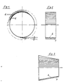
- Fig. 1 shows schematically a side view of the embodiment of the grinding sleeve according to the invention, in which the grinding flaps 1 are fastened overlapping on the outer surface on a carrier sleeve 2.
- the angle ⁇ to the tangential surface is shown schematically in the figure.
- the grinding lamellae can thus be arranged such that they extend in the tangential surface or are glued outwards at an angle ⁇ from the tangential surface.
- FIG. 2 schematically shows a sleeve according to the invention in view of the grinding surface, with no grinding flaps 1 being shown on part of the carrier sleeve 1.
- the abrasive layer from the individual abrasive flaps 1 is shown schematically in a schematic cross-sectional representation.
- Fig. 3 shows a grinding sleeve according to the invention with a conical carrier sleeve 2, on which the grinding flaps 1 are glued in a top view. Also in this representation, the sleeve, the abrasive layer is schematically indicated in cross section on the underside.
Landscapes
- Engineering & Computer Science (AREA)
- Mechanical Engineering (AREA)
- Polishing Bodies And Polishing Tools (AREA)
- Finish Polishing, Edge Sharpening, And Grinding By Specific Grinding Devices (AREA)
Applications Claiming Priority (2)
| Application Number | Priority Date | Filing Date | Title |
|---|---|---|---|
| DE4007928A DE4007928A1 (de) | 1990-03-13 | 1990-03-13 | Schleifhuelse |
| DE4007928 | 1990-03-13 |
Publications (2)
| Publication Number | Publication Date |
|---|---|
| EP0446626A1 true EP0446626A1 (fr) | 1991-09-18 |
| EP0446626B1 EP0446626B1 (fr) | 1994-08-10 |
Family
ID=6402061
Family Applications (1)
| Application Number | Title | Priority Date | Filing Date |
|---|---|---|---|
| EP91101877A Expired - Lifetime EP0446626B1 (fr) | 1990-03-13 | 1991-02-11 | Manchon de meulage |
Country Status (3)
| Country | Link |
|---|---|
| EP (1) | EP0446626B1 (fr) |
| DE (2) | DE4007928A1 (fr) |
| ES (1) | ES2060214T3 (fr) |
Cited By (4)
| Publication number | Priority date | Publication date | Assignee | Title |
|---|---|---|---|---|
| WO1997018060A1 (fr) * | 1995-11-14 | 1997-05-22 | Heinrich Lippert Gmbh | Outil pour traitement mecanique de surfaces |
| US5722881A (en) * | 1996-08-30 | 1998-03-03 | Merit Abrasive Products, Inc. | Flap wheel |
| EP0826462A1 (fr) * | 1996-08-30 | 1998-03-04 | Merit Abrasive Products, Inc. | Meule à lamelles |
| DE19812515A1 (de) * | 1998-03-21 | 1999-09-23 | M & F Entw & Patentverwertungs | Lamellenschleifwerkzeug |
Citations (3)
| Publication number | Priority date | Publication date | Assignee | Title |
|---|---|---|---|---|
| GB938223A (en) * | 1959-10-30 | 1963-10-02 | Rexall Drug Chemical | Abrasive devices |
| DE8523363U1 (de) * | 1985-08-14 | 1985-09-26 | Kemper-Kontakt Gert Kemper GmbH & Co KG, 5600 Wuppertal | Mit Schleiflamellen ausgestatteter Hohlzylinder |
| DE8903423U1 (de) * | 1989-03-18 | 1989-05-03 | Lukas-Erzett Vereinigte Schleif- und Fräswerkzeugfabriken GmbH & Co KG, 5250 Engelskirchen | Schleiflamellenscheibe |
Family Cites Families (2)
| Publication number | Priority date | Publication date | Assignee | Title |
|---|---|---|---|---|
| DE1986971U (de) * | 1968-06-06 | Kemper Kontakt Gert Kemper 5600 Wuppertal Vohwmkel | Schleif Putz oder Satimerscheibe | |
| US2774200A (en) * | 1955-10-10 | 1956-12-18 | Block Aleck | Abrasive polishing device |
-
1990
- 1990-03-13 DE DE4007928A patent/DE4007928A1/de active Granted
-
1991
- 1991-02-11 DE DE59102462T patent/DE59102462D1/de not_active Expired - Fee Related
- 1991-02-11 EP EP91101877A patent/EP0446626B1/fr not_active Expired - Lifetime
- 1991-02-11 ES ES91101877T patent/ES2060214T3/es not_active Expired - Lifetime
Patent Citations (3)
| Publication number | Priority date | Publication date | Assignee | Title |
|---|---|---|---|---|
| GB938223A (en) * | 1959-10-30 | 1963-10-02 | Rexall Drug Chemical | Abrasive devices |
| DE8523363U1 (de) * | 1985-08-14 | 1985-09-26 | Kemper-Kontakt Gert Kemper GmbH & Co KG, 5600 Wuppertal | Mit Schleiflamellen ausgestatteter Hohlzylinder |
| DE8903423U1 (de) * | 1989-03-18 | 1989-05-03 | Lukas-Erzett Vereinigte Schleif- und Fräswerkzeugfabriken GmbH & Co KG, 5250 Engelskirchen | Schleiflamellenscheibe |
Cited By (6)
| Publication number | Priority date | Publication date | Assignee | Title |
|---|---|---|---|---|
| WO1997018060A1 (fr) * | 1995-11-14 | 1997-05-22 | Heinrich Lippert Gmbh | Outil pour traitement mecanique de surfaces |
| US5722881A (en) * | 1996-08-30 | 1998-03-03 | Merit Abrasive Products, Inc. | Flap wheel |
| EP0826462A1 (fr) * | 1996-08-30 | 1998-03-04 | Merit Abrasive Products, Inc. | Meule à lamelles |
| US5871399A (en) * | 1996-08-30 | 1999-02-16 | Merit Abrasive Products, Inc. | Flap wheel |
| DE19812515A1 (de) * | 1998-03-21 | 1999-09-23 | M & F Entw & Patentverwertungs | Lamellenschleifwerkzeug |
| US6866572B1 (en) | 1998-03-21 | 2005-03-15 | M&F Entwicklungs | Plated grinding tool |
Also Published As
| Publication number | Publication date |
|---|---|
| DE4007928C2 (fr) | 1992-07-30 |
| EP0446626B1 (fr) | 1994-08-10 |
| ES2060214T3 (es) | 1994-11-16 |
| DE59102462D1 (de) | 1994-09-15 |
| DE4007928A1 (de) | 1991-09-19 |
Similar Documents
| Publication | Publication Date | Title |
|---|---|---|
| EP1131187B1 (fr) | Meule de rectification du type a eventail | |
| DE60317068T2 (de) | Schleifartikel mit einer schutzfolie mit vorsprüngen und verfahren zu ihrer herstellung und ihrer verwendung | |
| DE69301740T2 (de) | Schleifartikel und Verfahren | |
| DE102011108859B4 (de) | Rotationssymmetrisches Werkzeug zur spanenden Bearbeitung von Materialoberflächen, Scheibe oder Ringscheibe zur Verwendung bei einem derartigen Werkzeug sowie Verfahren zur Herstellung eines solchen Werkzeugs | |
| EP1120198B1 (fr) | Outil de meulage, dispositif ainsi équipé et procédé d'usinage de pièces mettant en oeuvre cet outil | |
| DE602005001842T2 (de) | Schleifelement | |
| EP3015222B1 (fr) | Disque de meulage | |
| EP0112405A1 (fr) | Elément d'attache utilisable dans des machines à meuler et à polir | |
| EP1321233A1 (fr) | Outil de polissage | |
| DE10042109C2 (de) | Polierwerkzeug | |
| EP0716903A1 (fr) | Article abrasif sur support | |
| EP0446626B1 (fr) | Manchon de meulage | |
| DE3717204A1 (de) | Aus fasermaterial, vorzugsweise metallfasern, bestehender kreisscheibenfoermiger koerper, insbesondere zur verwendung als schleif- und/oder polierscheibe sowie verfahren zu seiner herstellung | |
| EP4110552B1 (fr) | Outil de polissage | |
| EP0444272B1 (fr) | Disque de polissage à éléments flexibles périfériques | |
| DE3201825A1 (de) | Schleifscheibe | |
| EP3325216A1 (fr) | Meule munie d'un disque de support non-tissé | |
| DE102020001283A1 (de) | Polierwerkzeug | |
| WO2005095058A1 (fr) | Tete de meulage pour dispositif de meulage | |
| DE202020000786U1 (de) | Polierwerkzeug | |
| DE1239091C2 (de) | Schleifkoerper aus einer ungewebten Bahn aus synthetischen organischen Fasern | |
| DE9302902U1 (de) | Tellerfächerschleifscheibe | |
| DE9002384U1 (de) | Fächerstirnschleifscheibe | |
| DE29823200U1 (de) | Rotationsscheibe | |
| DE4231118A1 (de) | Stützteller für Schleifblätter |
Legal Events
| Date | Code | Title | Description |
|---|---|---|---|
| PUAI | Public reference made under article 153(3) epc to a published international application that has entered the european phase |
Free format text: ORIGINAL CODE: 0009012 |
|
| AK | Designated contracting states |
Kind code of ref document: A1 Designated state(s): DE ES FR GB IT |
|
| 17P | Request for examination filed |
Effective date: 19920309 |
|
| 17Q | First examination report despatched |
Effective date: 19930428 |
|
| GRAA | (expected) grant |
Free format text: ORIGINAL CODE: 0009210 |
|
| AK | Designated contracting states |
Kind code of ref document: B1 Designated state(s): DE ES FR GB IT |
|
| GBT | Gb: translation of ep patent filed (gb section 77(6)(a)/1977) |
Effective date: 19940810 |
|
| REF | Corresponds to: |
Ref document number: 59102462 Country of ref document: DE Date of ref document: 19940915 |
|
| ITF | It: translation for a ep patent filed | ||
| ET | Fr: translation filed | ||
| REG | Reference to a national code |
Ref country code: ES Ref legal event code: FG2A Ref document number: 2060214 Country of ref document: ES Kind code of ref document: T3 |
|
| PGFP | Annual fee paid to national office [announced via postgrant information from national office to epo] |
Ref country code: DE Payment date: 19950209 Year of fee payment: 5 |
|
| PGFP | Annual fee paid to national office [announced via postgrant information from national office to epo] |
Ref country code: ES Payment date: 19950216 Year of fee payment: 5 |
|
| PGFP | Annual fee paid to national office [announced via postgrant information from national office to epo] |
Ref country code: FR Payment date: 19950223 Year of fee payment: 5 |
|
| PLBE | No opposition filed within time limit |
Free format text: ORIGINAL CODE: 0009261 |
|
| STAA | Information on the status of an ep patent application or granted ep patent |
Free format text: STATUS: NO OPPOSITION FILED WITHIN TIME LIMIT |
|
| 26N | No opposition filed | ||
| PG25 | Lapsed in a contracting state [announced via postgrant information from national office to epo] |
Ref country code: ES Free format text: LAPSE BECAUSE OF NON-PAYMENT OF DUE FEES Effective date: 19960212 |
|
| PG25 | Lapsed in a contracting state [announced via postgrant information from national office to epo] |
Ref country code: FR Effective date: 19961031 |
|
| PG25 | Lapsed in a contracting state [announced via postgrant information from national office to epo] |
Ref country code: DE Effective date: 19961101 |
|
| REG | Reference to a national code |
Ref country code: FR Ref legal event code: ST |
|
| REG | Reference to a national code |
Ref country code: ES Ref legal event code: FD2A Effective date: 19990503 |
|
| REG | Reference to a national code |
Ref country code: GB Ref legal event code: IF02 |
|
| REG | Reference to a national code |
Ref country code: GB Ref legal event code: 732E |
|
| PG25 | Lapsed in a contracting state [announced via postgrant information from national office to epo] |
Ref country code: IT Free format text: LAPSE BECAUSE OF NON-PAYMENT OF DUE FEES;WARNING: LAPSES OF ITALIAN PATENTS WITH EFFECTIVE DATE BEFORE 2007 MAY HAVE OCCURRED AT ANY TIME BEFORE 2007. THE CORRECT EFFECTIVE DATE MAY BE DIFFERENT FROM THE ONE RECORDED. Effective date: 20050211 |
|
| PGFP | Annual fee paid to national office [announced via postgrant information from national office to epo] |
Ref country code: GB Payment date: 20100218 Year of fee payment: 20 |
|
| REG | Reference to a national code |
Ref country code: GB Ref legal event code: PE20 Expiry date: 20110210 |
|
| PG25 | Lapsed in a contracting state [announced via postgrant information from national office to epo] |
Ref country code: GB Free format text: LAPSE BECAUSE OF EXPIRATION OF PROTECTION Effective date: 20110210 |