EP0446650A1 - Dispositif de rassemblement de déchargement - Google Patents
Dispositif de rassemblement de déchargement Download PDFInfo
- Publication number
- EP0446650A1 EP0446650A1 EP91102220A EP91102220A EP0446650A1 EP 0446650 A1 EP0446650 A1 EP 0446650A1 EP 91102220 A EP91102220 A EP 91102220A EP 91102220 A EP91102220 A EP 91102220A EP 0446650 A1 EP0446650 A1 EP 0446650A1
- Authority
- EP
- European Patent Office
- Prior art keywords
- bending
- bench
- shaping machine
- bars
- conveyor belt
- Prior art date
- Legal status (The legal status is an assumption and is not a legal conclusion. Google has not performed a legal analysis and makes no representation as to the accuracy of the status listed.)
- Withdrawn
Links
Images

Classifications
-
- B—PERFORMING OPERATIONS; TRANSPORTING
- B21—MECHANICAL METAL-WORKING WITHOUT ESSENTIALLY REMOVING MATERIAL; PUNCHING METAL
- B21D—WORKING OR PROCESSING OF SHEET METAL OR METAL TUBES, RODS OR PROFILES WITHOUT ESSENTIALLY REMOVING MATERIAL; PUNCHING METAL
- B21D11/00—Bending not restricted to forms of material mentioned in only one of groups B21D5/00, B21D7/00, B21D9/00; Bending not provided for in groups B21D5/00 - B21D9/00; Twisting
- B21D11/10—Bending specially adapted to produce specific articles, e.g. leaf springs
- B21D11/12—Bending specially adapted to produce specific articles, e.g. leaf springs the articles being reinforcements for concrete
Definitions
- This invention concerns a collection and discharge bench for shaped rods or bars leaving a bending-shaping machine suitable to produce shaped rods or bars for building work.
- the invention concerns a collection and discharge bench for rods or bars intended for building work and leaving a bending-shaping machine after the required bends and shapes have been imparted to them, the bench being positioned alongside the outlet edge of the bending-shaping machin.
- the rods or bars may have any section or shape or be of any type.
- the shaped rods or bars receive a heavy thrust at the outlet of the bending-shaping machine, so that it becomes dangerous for the machine operator to approach the neighbourhood of the machine to collect the bent rods or bars.
- the present applicant has designed, tested and embodied the device of this invention so as to overcome the above shortcomings.
- the bench of the invention is fitted parallel to, and at the edge of the outlet from, a machine to bend and shape the shaped rods or bars.
- the collection and discharge bench is divided into two parts; the first part consists of a stationary tilted surface, whereas the second part is substantially horizontal and comprises a conveyor belt.
- the stationary surface is tilted by a given angle, which is the same as that of the bending-shaping machine, so that when the collection bench is positioned alongside the bending-shaping machine, they form one single tilted surface.
- the shaped rod or bar when thrust downwards from the bending-shaping machine at the end of the shaping step, slides down the stationary tilted surface of the collection and discharge bench and is stopped on the conveyor belt, which arranges to remove the rod or bar to an area which is safe for the machine operator.
- the conveyor belt is equipped with lateral abutment teeth to prevent the rods or bars falling and to retain them on the conveyor belt.
- the conveyor belt displaces the shaped rods or bars towards the operator, who can collect them and store them readily while staying in a shielded area.
- a first variant of the invention provides for the collection and discharge bench to be equipped with feet the height of which can be adjusted so as to make the stationary tilted surface mate with that of the bending-shaping machine if the machine has a height other than that of the collection and discharge bench.
- Another variant of the invention arranges to fit adjustment means to the stationary tilted surface of the collection and discharge bench.
- These adjustment means have the task of adjusting the inclination of the tilted surface of the bench when the surface is not tilted by the same degree as the bending-shaping machine.
- the bending-shaping machines may have their bending platform capable of being tilted by a variable angle.
- the stationary tilted surface is rotated about a rotation pivot, and its inclination is modified and adapted to the slope of the bending platform.
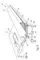
- Fig.1 shows a collection and discharge bench 10 positioned alongside the outlet edge for shaped rods or bars 13 leaving a bending-shaping machine 11.
- a stationary surface 12 of the collection and discharge bench 10 is tilted by a given angle " ⁇ " substantially the same as the angle " ⁇ '" of inclination of the bending-shaping machine 11.
- the shaped rods or bars 13 sheared on the bending-shaping machine 11 slide down the stationary tilted surface 12 and drop onto a conveyor belt 14.
- Fig.2 shows how the shaped rods or bars 13 leaving the bending-shaping machine 11 at a high speed are retained on the conveyor belt 14 by abutment teeth 11 which cooperate with an edge 23 of the collection and discharge bench 10.
- the elements of which the conveyor belt 14 consists may be made of rubber, wood, a plastic or soft metal.
- Fig.3 shows some variants which can be applied to the embodiment of Fig.1.
- a first variant provides for the bench 10 to be equipped with adjustable feet 16 suitable to adjust the height of the bench 10. This adjustment is carried out, for instance, by means of a rotary sleeve acting on the threaded stem of the foot 16. These rotary sleeves are actuated, for instance, by a motor 21 that acts on a transmission gear 22.
- Adjustment of the height of the bench 10 enables the inlet edge of the bench 10 to be brought to a height such that the stationary tilted surface 12 mates with the platform of the bending-shaping machine 11 so as to provide one single tilted surface.
- the inclination of the bending-shaping machine 11 and that of the stationary tilted surface 12 are the same.
- adjustment means 17 a jack for instance.
- Such adjustment means 17 have the task of ajusting the angle of inclination " ⁇ " of the stationary surface 12 when that angle of inclination " ⁇ '" is not the same as the angle of inclination " ⁇ " of the bending-shaping machine 11.
- the stationary tilted surface 12 By acting on the adjustment means 17 fitted to the stationary surface 12, that surface 12 can rotate about its axis of rotation 18.
- the stationary tilted surface 12, so as to be able to rotate is hinged to the bench 10 by a rotation pivot 19.
Landscapes
- Engineering & Computer Science (AREA)
- Mechanical Engineering (AREA)
- Bending Of Plates, Rods, And Pipes (AREA)
- Belt Conveyors (AREA)
- Grinding-Machine Dressing And Accessory Apparatuses (AREA)
Applications Claiming Priority (2)
| Application Number | Priority Date | Filing Date | Title |
|---|---|---|---|
| IT83346A IT1239665B (it) | 1990-03-15 | 1990-03-15 | Banco di raccolta ed evacuazione |
| IT8334690 | 1990-03-15 |
Publications (1)
| Publication Number | Publication Date |
|---|---|
| EP0446650A1 true EP0446650A1 (fr) | 1991-09-18 |
Family
ID=11320495
Family Applications (1)
| Application Number | Title | Priority Date | Filing Date |
|---|---|---|---|
| EP91102220A Withdrawn EP0446650A1 (fr) | 1990-03-15 | 1991-02-16 | Dispositif de rassemblement de déchargement |
Country Status (4)
| Country | Link |
|---|---|
| EP (1) | EP0446650A1 (fr) |
| JP (1) | JPH04224033A (fr) |
| CA (1) | CA2038311A1 (fr) |
| IT (1) | IT1239665B (fr) |
Families Citing this family (2)
| Publication number | Priority date | Publication date | Assignee | Title |
|---|---|---|---|---|
| JP5377896B2 (ja) * | 2008-06-26 | 2013-12-25 | 東陽建設工機株式会社 | 鉄筋加工装置 |
| CN103586361B (zh) * | 2013-11-07 | 2018-01-09 | 东莞市联洲知识产权运营管理有限公司 | 椭圆嵌合机的排料机构 |
Citations (3)
| Publication number | Priority date | Publication date | Assignee | Title |
|---|---|---|---|---|
| US2494103A (en) * | 1946-12-10 | 1950-01-10 | Penberthy Paul | Unloading device |
| DE2649234A1 (de) * | 1976-10-26 | 1978-05-03 | Olin Energy Systems Ltd | Vorrichtung zum beladen eines foerderers |
| EP0333695A2 (fr) * | 1988-03-17 | 1989-09-20 | EVG Entwicklungs- u. Verwertungs- Gesellschaft m.b.H. | Appareil à enlever des étriers en fil d'une machine à plier des étriers |
-
1990
- 1990-03-15 IT IT83346A patent/IT1239665B/it active IP Right Grant
-
1991
- 1991-02-16 EP EP91102220A patent/EP0446650A1/fr not_active Withdrawn
- 1991-03-12 JP JP3046824A patent/JPH04224033A/ja active Pending
- 1991-03-14 CA CA002038311A patent/CA2038311A1/fr not_active Abandoned
Patent Citations (3)
| Publication number | Priority date | Publication date | Assignee | Title |
|---|---|---|---|---|
| US2494103A (en) * | 1946-12-10 | 1950-01-10 | Penberthy Paul | Unloading device |
| DE2649234A1 (de) * | 1976-10-26 | 1978-05-03 | Olin Energy Systems Ltd | Vorrichtung zum beladen eines foerderers |
| EP0333695A2 (fr) * | 1988-03-17 | 1989-09-20 | EVG Entwicklungs- u. Verwertungs- Gesellschaft m.b.H. | Appareil à enlever des étriers en fil d'une machine à plier des étriers |
Also Published As
| Publication number | Publication date |
|---|---|
| IT9083346A0 (it) | 1990-03-14 |
| JPH04224033A (ja) | 1992-08-13 |
| IT1239665B (it) | 1993-11-11 |
| IT9083346A1 (it) | 1991-09-15 |
| CA2038311A1 (fr) | 1991-09-16 |
Similar Documents
| Publication | Publication Date | Title |
|---|---|---|
| DE10132695B4 (de) | Abrichten von Schleifwerkzeugen zum Verzahnungsschleifen | |
| EP1888306B1 (fr) | Dispositif d'assujettissement pour machines | |
| EP0446650A1 (fr) | Dispositif de rassemblement de déchargement | |
| DE4019104A1 (de) | Verfahren zum ausrichten, anheben und schwenken eines behaelters relativ zu einer vertikalen oeffnung | |
| DE3636314A1 (de) | Verfahren und vorrichtung zum schleifen langgestreckter gegenstaende | |
| EP0511619A1 (fr) | Dispositif pour déposer et former automatiquement des longueurs de saucisse en particulier de saucisses rôties | |
| DE69725701T2 (de) | Strassendeckenfräsgerät | |
| DE2125485A1 (de) | Schuhboden - aufrauhmaschine | |
| EP1371432A2 (fr) | Dispositif d'ébarbage | |
| DE2716347C3 (de) | Vorrichtung zum Verputzen von aufrecht stehenden Wandteilen aus Blockziegeln o.dgl | |
| WO1989010235A1 (fr) | Dispositif de coupe de pierres | |
| AT396270B (de) | Bearbeitungseinrichtung zur vergroesserung des lichten querschnittes der innenwand eines, insbesondere von der kreisform abweichenden profiles eines erdbauwerkes | |
| DE3807136C2 (fr) | ||
| DE60109634T2 (de) | Vorrichtung und verfahren zur zuführung von verpackungsmaterialien | |
| DE3410761A1 (de) | Verfahren und vorrichtung zum polieren von keilnutverzahnungen und zahnraedern unter verwendung synchron gedrehter zahnraeder | |
| DE69221334T2 (de) | Markierer für eine automatische sägekettenscharfvorrichtung der das ende eines scharfzyklus angibt | |
| JPS6155763B2 (fr) | ||
| EP0790105A2 (fr) | Dispositif de guidage pour une machine-outil à main | |
| EP1004392B1 (fr) | Table basculante pour une machine-outil | |
| CN113134559A (zh) | 一种钉子筛选及形变矫正一体装置 | |
| DE2243293C2 (de) | Vorrichtung zum Biegen von strangförmigen Werkstücken | |
| DE1685512C3 (de) | Maschine zum Aufrauhen der Randpartie eines aufgeleisteten Schuhoberteiles | |
| DE10251515B3 (de) | Sägemaschine und Sägeverfahren | |
| DE4116858A1 (de) | Maschine zum entfernen von schlacke und metallresten von schmelztiegeln | |
| DE3317987C2 (de) | Vorrichtung zum Zersägen von langgestrecktem Sägegut |
Legal Events
| Date | Code | Title | Description |
|---|---|---|---|
| PUAI | Public reference made under article 153(3) epc to a published international application that has entered the european phase |
Free format text: ORIGINAL CODE: 0009012 |
|
| AK | Designated contracting states |
Kind code of ref document: A1 Designated state(s): AT BE CH DE DK ES FR GB GR LI LU NL SE |
|
| 17P | Request for examination filed |
Effective date: 19920221 |
|
| 17Q | First examination report despatched |
Effective date: 19920427 |
|
| STAA | Information on the status of an ep patent application or granted ep patent |
Free format text: STATUS: THE APPLICATION HAS BEEN WITHDRAWN |
|
| 18W | Application withdrawn |
Withdrawal date: 19920909 |