EP0446684A1 - Vitre d'automobile possédant un double vitrage avec des éléments d'antenne - Google Patents
Vitre d'automobile possédant un double vitrage avec des éléments d'antenne Download PDFInfo
- Publication number
- EP0446684A1 EP0446684A1 EP91102521A EP91102521A EP0446684A1 EP 0446684 A1 EP0446684 A1 EP 0446684A1 EP 91102521 A EP91102521 A EP 91102521A EP 91102521 A EP91102521 A EP 91102521A EP 0446684 A1 EP0446684 A1 EP 0446684A1
- Authority
- EP
- European Patent Office
- Prior art keywords
- pane
- motor vehicle
- antenna element
- antenna
- vehicle window
- Prior art date
- Legal status (The legal status is an assumption and is not a legal conclusion. Google has not performed a legal analysis and makes no representation as to the accuracy of the status listed.)
- Granted
Links
- 238000010438 heat treatment Methods 0.000 claims abstract description 44
- 238000009413 insulation Methods 0.000 claims abstract description 13
- 125000006850 spacer group Chemical group 0.000 claims abstract description 8
- 239000004020 conductor Substances 0.000 claims description 14
- 239000011521 glass Substances 0.000 claims description 10
- 238000000576 coating method Methods 0.000 claims description 9
- 239000011248 coating agent Substances 0.000 claims description 7
- 238000005259 measurement Methods 0.000 claims description 2
- 239000012945 sealing adhesive Substances 0.000 description 4
- 230000000694 effects Effects 0.000 description 3
- 239000000203 mixture Substances 0.000 description 3
- 238000002955 isolation Methods 0.000 description 2
- 239000005336 safety glass Substances 0.000 description 2
- 238000010276 construction Methods 0.000 description 1
- 239000000463 material Substances 0.000 description 1
- 238000010257 thawing Methods 0.000 description 1
Images


Classifications
-
- H—ELECTRICITY
- H01—ELECTRIC ELEMENTS
- H01Q—ANTENNAS, i.e. RADIO AERIALS
- H01Q1/00—Details of, or arrangements associated with, antennas
- H01Q1/12—Supports; Mounting means
- H01Q1/1271—Supports; Mounting means for mounting on windscreens
Definitions
- the invention relates to a motor vehicle window pane in the form of a double-pane insulating glass unit with an inner pane, an outer pane and an insulation space defined via edge-side spacers for thermal insulation and / or sound insulation.
- the isolation space is filled with a gaseous medium, including gas mixtures or air.
- the edge spacers generally made of plastic, are mostly covered on the outside by a sealing adhesive. The distance between the isolation rooms is in the range of 2.5 mm and more.
- Outer pane denotes the pane which, when the motor vehicle pane is installed, faces the outside world.
- Inner pane refers to the pane which, when installed, points towards the vehicle interior. Motor vehicle windows of this type are mainly designed for thermal insulation, but also provide sound insulation.
- heating fields can also be metallic coatings. It is known to switch such heating fields as antennas or antenna elements.
- the invention has for its object to provide such a motor vehicle window in the form of a double-pane insulating glass unit - which should at the same time have at least one heating field.
- the invention relates to a motor vehicle pane in the form of a double pane insulating glass unit with an inner pane, an outer pane and an interior space defined by edge spacers, at least one antenna element in the form of an AM antenna element being arranged on at least one of the surfaces of the inner pane is and wherein the insulating space-side surface of the outer pane has at least one heating field, which can also be used as an antenna element.
- the heating field can be constructed from conductors printed on the surface of the outer pane on the side of the insulation space.
- the heating field can also be applied in the form of an electrically conductive surface field coating.
- the heating field can be used as an FM antenna element.
- Area field coating refers to a flat, for example trapezoidal, coating.
- work is carried out with elongated trapezoidal fields or strips which extend across the width of a motor vehicle window according to the invention and can be arranged one above the other.
- units which consist of two glass panes arranged with a space between them, with antenna elements (GB 21 30 018).
- the antenna elements are all arranged on the insulation-room-side surface of the outer pane or the inner pane of the unit. These units are not automotive windows.
- the design described serves to protectively encapsulate the antenna elements.
- two-pane insulating glass units are known in which one pane or both panes have a conductive coating on their surface on the insulating room side (US Pat. No. 2,497,507), but these are not antenna elements and the coatings are also not readily usable as antenna elements if the usual requirements are placed on the reception quality.
- the antenna element which is arranged on the surface of the inner pane on the inside of the vehicle.
- a heating field which is arranged in the manner described, can be used as the antenna element, with a good reception quality.
- this antenna element is an FM antenna element, which results in a surprisingly good reception quality for frequency-modulated electromagnetic waves, which is better than the reception that can usually be achieved via heating fields on motor vehicle windows for frequency-modulated electromagnetic waves.
- the received electrical energy can be decoupled in a known manner. It is particularly advantageous that the antenna elements can be brought close to the edge of the motor vehicle window without the inevitable electrical conductivity of the spacer material or the sealing adhesive having a disruptive effect. Surprisingly, the relatively large width of the spacing gap does not have a disruptive effect either.
- a combined AM / FM antenna element preferably in an L-shape, can be arranged on the surface of the inner pane on the vehicle. This can be done in different ways. If in the following from an L-shaped antenna element is spoken, it can basically be used as a combined AM / FM antenna element. However, it can also be used only as an FM antenna element or. AM antenna element can be used. Where there is talk of a combined AM / FM antenna element, this usually has an L shape.
- the invention also teaches to arrange a combined AM / FM antenna element and, in addition, at least one AM antenna element on the vehicle-side surface of the inner pane.
- the AM / FM antenna element can be constructed from an upper L-leg in the upper area of the inner pane and an approximately central L-web which runs vertically when installed, and the AM antenna element can be located above the AM / FM antenna element extend the entire width of the inner pane.
- the AM / FM antenna element can be optimized as described, consisting of an upper L-leg in the upper area of the inner pane and an approximately central L-shaped web that runs vertically when installed, but the AM antenna element can also be divided into two sub-elements, which extend below the upper L-leg and to the side of the L-bridge.
- the heating field or the heating fields is improved in their antenna effect in all these cases.
- this antenna can therefore be used for antenna diversity purposes.
- the AM antenna element is also designed as a heating field and in which this heating field and the heating field arranged on the outer pane are independent with regard to their heating function are switchable from each other. It is also within the scope of the invention to provide the inner pane with a heating field on one of its surfaces.
- the measures described last allow the outer pane and / or the inner pane to be dehumidified at short notice. Dehumidifying also means defrosting, especially with regard to the outer pane.
- the heating fields can always be those with surface coating as well as those with printed conductors.
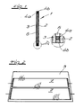
- the motor vehicle pane 1 shown in FIGS. 1 to 6 is designed as a double pane insulating glass unit.
- the inner pane 2 the outer pane 3 and an insulating space 5 defined by means of spacers 4a with sealing adhesive 4b.
- the insulating space 5 is filled with a gaseous medium, including gas mixtures and air.
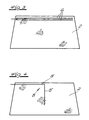
- the surface of the outer pane 3 on the insulating space side has two heating fields 7 in the form of printed conductors or in the form an electrically conductive surface field coating. At least one of these can be used simultaneously as an FM antenna element. They have the shape of two elongated strips.
- the antenna element of the outer pane 3, which is at the same time designed as a heating field 7, can be insulated with the AM antenna elements 6 and / or which are arranged on the inside of the inner pane 2 of the vehicle Combine antenna elements 8 arranged on the inner pane 2, which are shown in FIGS. 4 to 6.
- the L-legs were designated 8 ', the vertically running L-bars 8''.
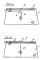
- the motor vehicle pane shown in FIGS. 7 to 12 connects to FIGS. 1 and 2 and is likewise designed as a double pane insulating glass unit. It has an inner pane 2, an outer pane 3 and an insulating space 5 defined by means of spacers 4a with sealing adhesive 4b on the edge.
- the insulating space 5 is filled with a gaseous medium, including gas mixtures and air.
- the insulation space-side surface of the outer pane 3 has at least one heating field 7. At least one of the heating fields 7 could be used as an FM antenna element.
- an FM antenna element 9 is arranged on the surface of the inner pane 2 on the vehicle interior.
- a heating field 10 is also provided.
- the arrangement is also made so that the transverse to the direction of the heating conductor 11 antenna conductors 12 are each connected to equipotential points P of the heating conductor 11, which on the heating conductors 11, z. B. were determined by measurement.
- the antenna conductors 12 are set up to receive horizontally and vertically polarized radio waves. According to FIG. 8, there are no galvanic connections between the antenna conductors 12 outside of the heating field 10 Connections arranged.
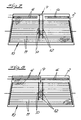
- the reference numerals of FIGS. 7 and 8 are found, as far as they match.
- the FM antenna is designed as a single L-antenna 13, the horizontal L-leg 14 of which is above and below that in the Area of the upper edge of the disk arranged AM antenna 6 is arranged.
- FIG. 11 shows how a heating field 10 can be arranged on the inner pane 2, which can also be used as an FM antenna. It can be located on the surface on the side of the insulation room or also on the surface on the inside of the vehicle. 11, it may be located on the surface of the inner pane 2 on the side of the insulation space.
- the antenna configuration shown in FIG. 12 is also located on the vehicle-side surface of the inner pane 2.
- the FM antenna is designed as an L-antenna 13, which runs with its horizontal L-leg 14 above the AM antenna 6 arranged in the region of the upper edge of the pane and whose vertical L-leg is doubled.
- Antenna configurations as described and illustrated above are known per se. According to the invention, they are used in a special way in a motor vehicle window according to FIGS. 1 to 6.
Landscapes
- Details Of Aerials (AREA)
Applications Claiming Priority (6)
| Application Number | Priority Date | Filing Date | Title |
|---|---|---|---|
| DE4007641 | 1990-03-10 | ||
| DE4007641 | 1990-03-10 | ||
| DE19904019268 DE4019268A1 (de) | 1990-03-10 | 1990-06-16 | Kraftfahrzeugscheibe in form einer zweischeiben-isolierglaseinheit mit antennenelementen |
| DE4019268 | 1990-06-16 | ||
| DE4036937 | 1990-11-20 | ||
| DE19904036937 DE4036937A1 (de) | 1990-06-16 | 1990-11-20 | Kraftfahrzeugscheibe in form einer zweischeiben-isolierglaseinheit mit antennenelementen |
Publications (2)
| Publication Number | Publication Date |
|---|---|
| EP0446684A1 true EP0446684A1 (fr) | 1991-09-18 |
| EP0446684B1 EP0446684B1 (fr) | 1995-06-21 |
Family
ID=27200959
Family Applications (1)
| Application Number | Title | Priority Date | Filing Date |
|---|---|---|---|
| EP91102521A Expired - Lifetime EP0446684B1 (fr) | 1990-03-10 | 1991-02-21 | Vitre d'automobile possédant un double vitrage avec des éléments d'antenne |
Country Status (3)
| Country | Link |
|---|---|
| EP (1) | EP0446684B1 (fr) |
| JP (1) | JPH0595220A (fr) |
| DE (1) | DE59105751D1 (fr) |
Cited By (3)
| Publication number | Priority date | Publication date | Assignee | Title |
|---|---|---|---|---|
| WO2007054694A1 (fr) | 2005-11-08 | 2007-05-18 | Nel Technologies Limited | Dispositif antibuée et élément de visualisation antibuée |
| EP1837948A1 (fr) * | 2006-03-22 | 2007-09-26 | PILKINGTON Automotive Deutschland GmbH | Ensemble d'antenne amélioré |
| CN115734902A (zh) * | 2021-06-30 | 2023-03-03 | 法国圣戈班玻璃厂 | 带有天线板的玻璃窗以及用于制造这种玻璃窗的方法 |
Families Citing this family (4)
| Publication number | Priority date | Publication date | Assignee | Title |
|---|---|---|---|---|
| JP5738177B2 (ja) * | 2011-12-28 | 2015-06-17 | 日本板硝子株式会社 | 車両用ガラスアンテナ |
| JP7229944B2 (ja) * | 2017-06-09 | 2023-02-28 | サン-ゴバン グラス フランス | 埋め込み式データトランスポンダを備えるラミネートガラス |
| CN108341601A (zh) * | 2018-02-13 | 2018-07-31 | 江苏奥蓝工程玻璃有限公司 | 一种隔热夹层玻璃的制备方法 |
| CN114069190B (zh) * | 2020-08-07 | 2025-09-16 | 福耀玻璃工业集团股份有限公司 | 一种圆极化微带天线及obu装置及车辆玻璃 |
Citations (6)
| Publication number | Priority date | Publication date | Assignee | Title |
|---|---|---|---|---|
| US2497507A (en) * | 1942-10-05 | 1950-02-14 | Libbey Owens Ford Glass Co | Electrically conducting multiple panel structure |
| DE2615356A1 (de) * | 1976-04-08 | 1977-10-27 | Terhaar Bernhard Dr | Isolierverglasung |
| FR2601194A1 (fr) * | 1986-07-04 | 1988-01-08 | Central Glass Co Ltd | Antenne de glace de fenetre de vehicule utilisant un film conducteur transparent |
| DE3910031A1 (de) * | 1988-03-31 | 1989-10-19 | Nippon Sheet Glass Co Ltd | Fahrzeug-scheibenantenne |
| EP0346591A1 (fr) * | 1988-06-14 | 1989-12-20 | FUBA Hans Kolbe & Co | Antenne pour la réception des ondes métriques installée ensemble avec un chauffage de pare-brise de véhicule. |
| EP0396033A2 (fr) * | 1989-05-01 | 1990-11-07 | FUBA Automotive GmbH | Antenne pour une vitre d'un vehicule automobile pour des fréquences audessus de la gamme de la haute fréquence |
Family Cites Families (2)
| Publication number | Priority date | Publication date | Assignee | Title |
|---|---|---|---|---|
| JPS5067751U (fr) * | 1973-10-24 | 1975-06-17 | ||
| US4633262A (en) * | 1982-09-27 | 1986-12-30 | Rogers Corporation | Microstrip antenna with protective casing |
-
1991
- 1991-02-21 EP EP91102521A patent/EP0446684B1/fr not_active Expired - Lifetime
- 1991-02-21 DE DE59105751T patent/DE59105751D1/de not_active Expired - Fee Related
- 1991-03-08 JP JP3043776A patent/JPH0595220A/ja active Pending
Patent Citations (6)
| Publication number | Priority date | Publication date | Assignee | Title |
|---|---|---|---|---|
| US2497507A (en) * | 1942-10-05 | 1950-02-14 | Libbey Owens Ford Glass Co | Electrically conducting multiple panel structure |
| DE2615356A1 (de) * | 1976-04-08 | 1977-10-27 | Terhaar Bernhard Dr | Isolierverglasung |
| FR2601194A1 (fr) * | 1986-07-04 | 1988-01-08 | Central Glass Co Ltd | Antenne de glace de fenetre de vehicule utilisant un film conducteur transparent |
| DE3910031A1 (de) * | 1988-03-31 | 1989-10-19 | Nippon Sheet Glass Co Ltd | Fahrzeug-scheibenantenne |
| EP0346591A1 (fr) * | 1988-06-14 | 1989-12-20 | FUBA Hans Kolbe & Co | Antenne pour la réception des ondes métriques installée ensemble avec un chauffage de pare-brise de véhicule. |
| EP0396033A2 (fr) * | 1989-05-01 | 1990-11-07 | FUBA Automotive GmbH | Antenne pour une vitre d'un vehicule automobile pour des fréquences audessus de la gamme de la haute fréquence |
Cited By (4)
| Publication number | Priority date | Publication date | Assignee | Title |
|---|---|---|---|---|
| WO2007054694A1 (fr) | 2005-11-08 | 2007-05-18 | Nel Technologies Limited | Dispositif antibuée et élément de visualisation antibuée |
| US8399805B2 (en) | 2005-11-08 | 2013-03-19 | Nel Technologies Limited | Anti-fogging device and anti-fogging viewing member |
| EP1837948A1 (fr) * | 2006-03-22 | 2007-09-26 | PILKINGTON Automotive Deutschland GmbH | Ensemble d'antenne amélioré |
| CN115734902A (zh) * | 2021-06-30 | 2023-03-03 | 法国圣戈班玻璃厂 | 带有天线板的玻璃窗以及用于制造这种玻璃窗的方法 |
Also Published As
| Publication number | Publication date |
|---|---|
| DE59105751D1 (de) | 1995-07-27 |
| EP0446684B1 (fr) | 1995-06-21 |
| JPH0595220A (ja) | 1993-04-16 |
Similar Documents
| Publication | Publication Date | Title |
|---|---|---|
| EP0760537B1 (fr) | Antenne de vitrage pour véhicule automobile | |
| DE3914424C2 (fr) | ||
| DE2060418C3 (de) | Fahrzeugantennenanordnung | |
| DE2360672C3 (de) | Auf oder in einer Sichtscheibe für Kraftfahrzeuge angeordnetes Leitersystem mit Heiz- und Antennenfunktion | |
| EP0332898B1 (fr) | Fenêtre pour véhicule | |
| DE3721934C2 (fr) | ||
| DE69431288T2 (de) | Scheibenantenne und Verfahren zum Entwerfen einer derartigen Antenne | |
| DE10106125B4 (de) | Kraftfahrzeugscheibe mit Antennenstrukturen | |
| DE3743099A1 (de) | Kraftfahrzeug-fensterglasantenne mit benutzung einer transparenten leitfaehigen schicht | |
| DE10146439C1 (de) | Fahrzeugantennenscheibe | |
| DE69313165T2 (de) | Scheibenantenne für Kraftfahrzeug | |
| DE2160458A1 (de) | Verfahren zur Verbesserung der Empfangsleistung einer mit Antennenleitern versehenen Sichtscheibe für Kraftfahrzeuge | |
| DE3641738C2 (fr) | ||
| EP0446684B1 (fr) | Vitre d'automobile possédant un double vitrage avec des éléments d'antenne | |
| DE4237818A1 (de) | Scheibenantenne für Kraftfahrzeuge | |
| DE10314094A1 (de) | Antennenscheibe | |
| DE4019268C2 (fr) | ||
| DE69129610T2 (de) | Scheibenantenne für Kraftfahrzeug | |
| EP0004001B1 (fr) | Vitre de véhicule comportant une antenne | |
| DE3910031A1 (de) | Fahrzeug-scheibenantenne | |
| EP1404153B1 (fr) | Vitrage chauffant électrique | |
| DE2429628A1 (de) | Empfangsantenne fuer kraftfahrzeuge | |
| DE2440439A1 (de) | Kraftfahrzeug mit antennenscheibe | |
| DE19527304C1 (de) | Für den Empfang von Radiowellen im UKW-Bereich eingerichtete Kraftfahrzeugscheibe | |
| DE68921998T2 (de) | Kraftfahrzeugantennensystem. |
Legal Events
| Date | Code | Title | Description |
|---|---|---|---|
| PUAI | Public reference made under article 153(3) epc to a published international application that has entered the european phase |
Free format text: ORIGINAL CODE: 0009012 |
|
| 17P | Request for examination filed |
Effective date: 19910720 |
|
| AK | Designated contracting states |
Kind code of ref document: A1 Designated state(s): BE DE ES FR GB IT SE |
|
| 17Q | First examination report despatched |
Effective date: 19931116 |
|
| RAP1 | Party data changed (applicant data changed or rights of an application transferred) |
Owner name: FLACHGLAS AKTIENGESELLSCHAFT |
|
| GRAA | (expected) grant |
Free format text: ORIGINAL CODE: 0009210 |
|
| AK | Designated contracting states |
Kind code of ref document: B1 Designated state(s): BE DE ES FR GB IT SE |
|
| PG25 | Lapsed in a contracting state [announced via postgrant information from national office to epo] |
Ref country code: ES Free format text: THE PATENT HAS BEEN ANNULLED BY A DECISION OF A NATIONAL AUTHORITY Effective date: 19950621 |
|
| REF | Corresponds to: |
Ref document number: 59105751 Country of ref document: DE Date of ref document: 19950727 |
|
| ITF | It: translation for a ep patent filed | ||
| GBT | Gb: translation of ep patent filed (gb section 77(6)(a)/1977) |
Effective date: 19950822 |
|
| PG25 | Lapsed in a contracting state [announced via postgrant information from national office to epo] |
Ref country code: SE Effective date: 19950921 |
|
| ET | Fr: translation filed | ||
| PLBE | No opposition filed within time limit |
Free format text: ORIGINAL CODE: 0009261 |
|
| STAA | Information on the status of an ep patent application or granted ep patent |
Free format text: STATUS: NO OPPOSITION FILED WITHIN TIME LIMIT |
|
| 26N | No opposition filed | ||
| PGFP | Annual fee paid to national office [announced via postgrant information from national office to epo] |
Ref country code: GB Payment date: 19970129 Year of fee payment: 7 |
|
| PGFP | Annual fee paid to national office [announced via postgrant information from national office to epo] |
Ref country code: FR Payment date: 19970221 Year of fee payment: 7 |
|
| PGFP | Annual fee paid to national office [announced via postgrant information from national office to epo] |
Ref country code: BE Payment date: 19970306 Year of fee payment: 7 |
|
| PG25 | Lapsed in a contracting state [announced via postgrant information from national office to epo] |
Ref country code: GB Free format text: LAPSE BECAUSE OF NON-PAYMENT OF DUE FEES Effective date: 19980221 |
|
| PG25 | Lapsed in a contracting state [announced via postgrant information from national office to epo] |
Ref country code: FR Free format text: THE PATENT HAS BEEN ANNULLED BY A DECISION OF A NATIONAL AUTHORITY Effective date: 19980228 Ref country code: BE Free format text: LAPSE BECAUSE OF NON-PAYMENT OF DUE FEES Effective date: 19980228 |
|
| BERE | Be: lapsed |
Owner name: FLACHGLAS A.G. Effective date: 19980228 |
|
| GBPC | Gb: european patent ceased through non-payment of renewal fee |
Effective date: 19980221 |
|
| REG | Reference to a national code |
Ref country code: FR Ref legal event code: ST |
|
| PGFP | Annual fee paid to national office [announced via postgrant information from national office to epo] |
Ref country code: DE Payment date: 19991222 Year of fee payment: 10 |
|
| PG25 | Lapsed in a contracting state [announced via postgrant information from national office to epo] |
Ref country code: DE Free format text: LAPSE BECAUSE OF NON-PAYMENT OF DUE FEES Effective date: 20011201 |
|
| PG25 | Lapsed in a contracting state [announced via postgrant information from national office to epo] |
Ref country code: IT Free format text: LAPSE BECAUSE OF NON-PAYMENT OF DUE FEES;WARNING: LAPSES OF ITALIAN PATENTS WITH EFFECTIVE DATE BEFORE 2007 MAY HAVE OCCURRED AT ANY TIME BEFORE 2007. THE CORRECT EFFECTIVE DATE MAY BE DIFFERENT FROM THE ONE RECORDED. Effective date: 20050221 |