EP0446736B1 - Strapping machine for pallets - Google Patents
Strapping machine for pallets Download PDFInfo
- Publication number
- EP0446736B1 EP0446736B1 EP91103169A EP91103169A EP0446736B1 EP 0446736 B1 EP0446736 B1 EP 0446736B1 EP 91103169 A EP91103169 A EP 91103169A EP 91103169 A EP91103169 A EP 91103169A EP 0446736 B1 EP0446736 B1 EP 0446736B1
- Authority
- EP
- European Patent Office
- Prior art keywords
- bayonet
- hoop
- aggregate
- casing
- pallet
- Prior art date
- Legal status (The legal status is an assumption and is not a legal conclusion. Google has not performed a legal analysis and makes no representation as to the accuracy of the status listed.)
- Expired - Lifetime
Links
- 229920001169 thermoplastic Polymers 0.000 claims description 2
- 239000004416 thermosoftening plastic Substances 0.000 claims description 2
- 230000000295 complement effect Effects 0.000 claims 1
- 238000007789 sealing Methods 0.000 claims 1
- 239000003795 chemical substances by application Substances 0.000 description 2
- 229910000831 Steel Inorganic materials 0.000 description 1
- 230000000712 assembly Effects 0.000 description 1
- 238000000429 assembly Methods 0.000 description 1
- 238000010276 construction Methods 0.000 description 1
- 230000000284 resting effect Effects 0.000 description 1
- 238000000926 separation method Methods 0.000 description 1
- 239000010959 steel Substances 0.000 description 1
- 230000001502 supplementing effect Effects 0.000 description 1
- 238000004804 winding Methods 0.000 description 1
Images

Classifications
-
- B—PERFORMING OPERATIONS; TRANSPORTING
- B65—CONVEYING; PACKING; STORING; HANDLING THIN OR FILAMENTARY MATERIAL
- B65B—MACHINES, APPARATUS OR DEVICES FOR, OR METHODS OF, PACKAGING ARTICLES OR MATERIALS; UNPACKING
- B65B13/00—Bundling articles
- B65B13/02—Applying and securing binding material around articles or groups of articles, e.g. using strings, wires, strips, bands or tapes
- B65B13/04—Applying and securing binding material around articles or groups of articles, e.g. using strings, wires, strips, bands or tapes with means for guiding the binding material around the articles prior to severing from supply
- B65B13/06—Stationary ducts or channels
Definitions
- the invention relates to a machine for strapping palletized packaged goods including the pallet with a strapping agent, in particular a thermoplastic band, consisting essentially of a portal, a bayonet supplementing this to a circumferential band guide channel for the strapping agent and an assembly for the preparation, conveying and the closure of the strapping means, both the bayonet and the unit are each equipped with a drive motor and a linear guide for their essentially horizontal relative movement to the packaged goods and portal.
- a strapping agent in particular a thermoplastic band, consisting essentially of a portal, a bayonet supplementing this to a circumferential band guide channel for the strapping agent and an assembly for the preparation, conveying and the closure of the strapping means
- both the bayonet and the unit are each equipped with a drive motor and a linear guide for their essentially horizontal relative movement to the packaged goods and portal.
- the linear guides are realized by means of ball screws. Electric motors each drive a threaded spindle along which a ball screw nut mounted on it is adjusted, to which the movable machine parts are in turn attached.
- the bayonet and / or unit is driven by chain drives controlled by end positions or pneumatic cable cylinders.
- the invention is therefore based on the object of making available a machine which is outlined in the preamble of claim 1 and which is capable of fulfilling the safety requirements in a considerably simplified manner and which can be used in the technically inexpensive linear guides.
- the invention solves this problem primarily and essentially by using rotating field magnets as drive motors for the bayonet and the unit.
- Three-phase magnets are three-phase motors with squirrel-cage rotors, the stators of which are 'overwound', i.e. are provided with a significantly larger number of turns than usual. They are designed electrically so that they can be used at rated voltage with a braked shaft in continuous and intermittent operation with unlimited duty cycle and develop their greatest torque (standstill torque). In principle, you could compare a rotating field magnet with an electric spring with infinite spring travel.
- the invention utilizes these properties of rotating field magnets, which were previously used, for example, to drive church bells or for the winding devices on drums of trailing cables for cranes, to an astonishingly advantageous extent to control the linear movements of the bayonet and / or assembly.
- a rotating field magnet as a direct drive motor for the bayonet and / or unit is considerably simpler and therefore less expensive than, in particular, a ball screw drive or a pneumatic cable cylinder, which besides the electrical connection, which is in any case necessary for the machine, also requires a compressed air supply.
- the linear drive can consequently be designed in a simplest embodiment, which is characterized approximately in that a drive pinion is arranged on the shaft of the rotating field magnet, which meshes with a rack attached to the bayonet or to the unit. It is of further advantage, in particular for reasons of constructive simplification, if the toothed rack is connected to carriages guided on a carrier rail by means of rollers.
- a pallet strapping machine designated overall by 10, includes a portal 11 with posts 12 and 13 and a bar 14, the actual machine unit 15 and a bayonet 16.
- the palletized packaged goods 17/18 are first moved into the portal by means of a transport device indicated by 20, such as roller conveyors. Then the bayonet 16, which is waiting in the rest position on the right in FIG. 1, passes under the pallet 17 and docks at 21 on the post 12. In the usual way, the assembly now shoots the strapping means in the direction of circulation 22 through the strapping channel 19 until the front end of the strapping means is inserted into a closure head 23 of the assembly 15 and is held there. Now the unit 15 moves against that Packaged goods 18 in the position 15 'shown in dashed lines, and the strapping means is then withdrawn against its weft direction, thus pulled out of the strapping channel and finally tightened around the packaged goods. The overlapping strapping sections are ultimately firmly connected to one another in the closure head 23, that is to say generally thermally welded.
- the drive 24 for the bayonet 16 and the drive 25 for the assembly 15 are new and essential to the invention, also in connection with their linear guides 31 and 38.
- a rotating field magnet 26 serves as the drive motor for the bayonet 16.
- a pinion 28 is rotatably mounted on its shaft 27 (FIG. 2) and meshes with a toothed rack 29 fastened under the bayonet 16. With 30 the strapping channel in the bayonet 16 is designated, which is mounted on a very simple linear guide 31.
- the linear guide 31 comprises a rail 33 carried by two supports 32 standing on the floor with rail heads 34 made of round steel bars, on which rollers 35 rotatably mounted on carriages 36 run.
- the bayonet 16 is in turn attached to the carriage.
- the pinion 28 drives the bayonet mounted on the linear guide described and, depending on the direction of rotation, either pushes it forward or pulls it back.
- a very similar drive is provided for the assembly 15, whose rotating field magnet is designated 37 and its linear guide is designated 38 (FIG. 1).
- the shaft of the rotating field magnet 37 meshes with a rack secured under the assembly 15.
- the linear guide 38 is attached to the top of the unit 15. Thereby, i.e. due to the spatial separation of drive and guidance, a very stable position of the assembly 15 is achieved.
- the guide rail 39 is connected to the unit 15 in a uniform movement, while the rollers 40 are mounted on a bracket 41 held in a fixed position.
Landscapes
- Engineering & Computer Science (AREA)
- Mechanical Engineering (AREA)
- Basic Packing Technique (AREA)
Description
Die Erfindung bezieht sich auf eine Maschine zum Umreifen palettierten Packgutes einschließlich der Palette mit einem Umreifungsmittel, insbesondere einem thermoplastischen Band, im wesentlichen bestehend aus einem Portal, einem dieses zu einem umlaufenden Bandführungskanal für das Umreifungsmittel ergänzenden Bajonett und einem Aggregat für die Bereithaltung, Förderung und den Verschluß des Umreifungsmittels, wobei sowohl das Bajonett als auch das Aggregat jeweils mit einem Antriebsmotor und einer Linearführung für ihre im wesentlichen horizontale Relativbewegung zu Packgut und Portal ausgerüstet sind.The invention relates to a machine for strapping palletized packaged goods including the pallet with a strapping agent, in particular a thermoplastic band, consisting essentially of a portal, a bayonet supplementing this to a circumferential band guide channel for the strapping agent and an assembly for the preparation, conveying and the closure of the strapping means, both the bayonet and the unit are each equipped with a drive motor and a linear guide for their essentially horizontal relative movement to the packaged goods and portal.
Derartige Maschinen sind in verschiedenen Ausführungen diverser Hersteller bekannt. Problematisch ist die Führung und Steuerung der linearbeweglichen Maschinenteile, nämlich des Bajonetts - auch Lanze oder Schwert genannt - und des Aggregats.Such machines are known in various designs from various manufacturers. The guidance and control of the linearly movable machine parts, namely the bayonet - also called lance or sword - and the unit is problematic.
Bei einer bekannten Maschine sind die Linearführungen mittels Kugelgewindetrieben realisiert. Dabei treiben Elektromotoren jeweils eine Gewindespindel an, längs der sich eine auf ihr lagernde Kugelgewindemutter verstellt, an der wiederum die verfahrbaren Maschinenteile befestigt sind. Bei Maschinen weiterer bekannter Bauarten erfolgt der Antrieb von Bajonett und/oder Aggregat über endlagengesteuerte Kettentriebe oder pneumatische Seilzylinder.In a known machine, the linear guides are realized by means of ball screws. Electric motors each drive a threaded spindle along which a ball screw nut mounted on it is adjusted, to which the movable machine parts are in turn attached. In machines of other known types, the bayonet and / or unit is driven by chain drives controlled by end positions or pneumatic cable cylinders.
Alle bekannten Ausführungen sind konstruktionsbedingt sehr aufwendig. Besonders problematisch sind sie hinsichtlich der zu berücksichtigenden Sicherheitsanforderungen. Denn das in den Umreifungsbereich einlaufende Bajonett kann in seiner Bewegungsbahn stehende Personen erheblich verletzen. Diese Gefahr besteht auch hinsichtlich des verfahrbaren Aggregats. Deshalb sind bei den bekannten Maschinen aufwendige Sicherheitsvorkehrungen getroffen, die mit Hilfe ausgeklügelter Steuerungen mehr oder minder effizient die Antriebe abschalten, wenn Bajonett und/oder Aggregate auf ihren Verstellwegen auf Hindernisse treffen. Besonders schwierig ist es dabei, die in Abhängigkeit vom jeweiligen Verstellweg sehr unterschiedlichen Massenträgheitsmomente der in zumeist sehr schneller Bewegung befindlichen Maschinenteile so zu beherrschen, daß die Antriebe möglichst ohne nennenswerte Verzögerung sofort abschalten. In der Regel ist aber der gefürchtete Nachlauf nicht zu vermeiden. Jedenfalls erfordern solche Sicherheitsmaßnahmen erblichen steuerungstechnischen Aufwand sowohl in elektrischer als vor allem auch in mechanischer Hinsicht.All known designs are very complex due to their construction. They are particularly problematic with regard to the security requirements to be taken into account. This is because the bayonet entering the strapping area can seriously injure people standing in its path of movement. This danger also exists with regard to the movable unit. For this reason, elaborate safety precautions have been taken in the known machines which, with the aid of sophisticated controls, switch off the drives more or less efficiently when the bayonet and / or assemblies encounter obstacles on their adjustment paths. It is particularly difficult to control the mass moments of inertia, which are very different depending on the respective adjustment path, of the machine parts, which are usually moving very quickly, in such a way that the drives switch off immediately without any significant delay. As a rule, the dreaded wake cannot be avoided. In any case, such security measures require hereditary control expenditure, both in electrical and, above all, in mechanical terms.
Der Erfindung liegt folglich die Aufgabe zugrunde, eine Maschine der im Oberbegriff des Anspruchs 1 näher umrissenen Art verfügbar zu machen, die die Sicherheitsanforderungen in erheblich vereinfachter Art und Weise zu erfüllen in der Lage ist und bei der technisch wenig aufwendige Linearführungen verwendbar sind.The invention is therefore based on the object of making available a machine which is outlined in the preamble of claim 1 and which is capable of fulfilling the safety requirements in a considerably simplified manner and which can be used in the technically inexpensive linear guides.
Die Erfindung löst diese Aufgabe in erster Linie und im wesentlichen durch die Verwendung von Drehfeldmagneten als Antriebsmotoren für das Bajonett und das Aggregat.The invention solves this problem primarily and essentially by using rotating field magnets as drive motors for the bayonet and the unit.
Drehfeldmagnete sind Drehstrommotoren mit Käfigläufern, deren Statoren 'überwickelt', d.h. mit einer erheblich größeren Windungszahl als üblich versehen sind. Sie sind elektrisch so ausgelegt, daß sie bei Nennspannung mit festgebremster Welle im Dauer- und Ausssetzbetrieb mit unbegrenzter Einschaltdauer eingesetzt werden können und dabei ihr größtes Drehmoment (Stillstandsmoment) entwickeln. Im Prinzip könnte man einen Drehfeldmagneten mit einer elektrischen Feder mit unendlichem Federweg vergleichen.Three-phase magnets are three-phase motors with squirrel-cage rotors, the stators of which are 'overwound', i.e. are provided with a significantly larger number of turns than usual. They are designed electrically so that they can be used at rated voltage with a braked shaft in continuous and intermittent operation with unlimited duty cycle and develop their greatest torque (standstill torque). In principle, you could compare a rotating field magnet with an electric spring with infinite spring travel.
Diese Eigenschaften von Drehfeldmagneten, die bisher beispielsweise zum Antrieb von Kirchenglocken oder für die Wickelvorrichtungen an Trommeln von Schleppkabeln für Krane eingesetzt werden, nutzt die Erfindung in verblüffend vorteilhaftem Umfang zur Steuerung der Linearbewegungen von Bajonett und/oder Aggregat aus.The invention utilizes these properties of rotating field magnets, which were previously used, for example, to drive church bells or for the winding devices on drums of trailing cables for cranes, to an astonishingly advantageous extent to control the linear movements of the bayonet and / or assembly.
Sobald der Drehfeldmagnet mit Spannung beaufschlagt wird, also bei zurückgefahrenem Bajonett bzw. Aggregat, liegt sofort das maximale Drehmoment an, so daß die Bewegungen unverzüglich eingeleitet werden. Am Ende ihrer jeweiligen Bewegungsbahn - das Bajonett ist am Portal angedockt, der Umreifungsmittel-Verschlußkopf des Aggregats am Packgut positioniert - werden die verfahrbaren Maschinenteile unter dem Einfluß des Restdrehmoments in Position gehalten. Wenn jedoch Bajonett und/oder Aggregat auf ein Hindernis treffen, werden sie an ihrer weiteren Bewegung gehindert, ohne daß - und dies ist für die Erfindung von fundamentaler Bedeutung - der Drehfeldmagnet stromlos geschaltet werden muß. Er bleibt schlicht stehen, ohne daß irgendeine Abschaltvorrichtung in Funktion gesetzt werden müßte. Damit entfallen sämtliche bislang notwendigen Notsteuerungs- bzw. -schaltungsmaßnahmen.As soon as voltage is applied to the rotating field magnet, i.e. when the bayonet or unit is retracted, the maximum torque is immediately applied, so that the movements are initiated immediately. At the end of their respective trajectory - the bayonet is docked to the portal, the strapping head of the unit is positioned on the packaged goods - the movable machine parts are held in position under the influence of the residual torque. However, if bayonet and / or aggregate encounter an obstacle, they are prevented from moving further without the rotary field magnet having to be switched off, and this is of fundamental importance for the invention. It simply stops without any switch-off device having to be activated. This eliminates all emergency control and switching measures that were previously necessary.
Im übrigen ist ein Drehfeldmagnet als unmittelbarer Antriebsmotor für Bajonett und/oder Aggregat erheblich einfacher und somit kostengünstiger als insbesondere ein Kugelgewindetrieb oder ein pneumatischer Seilzugzylinder, der ja im übrigen neben dem ohnenhin maschinennotwendigen elektrischen Anschluß auch eine Druckluftspeisung benötigt.In addition, a rotating field magnet as a direct drive motor for the bayonet and / or unit is considerably simpler and therefore less expensive than, in particular, a ball screw drive or a pneumatic cable cylinder, which besides the electrical connection, which is in any case necessary for the machine, also requires a compressed air supply.
Bei Verwendung von Drehfeldmagneten kann der Linearantrieb folglich in einer simpelsten Ausführung ausgelegt werden, die etwa dadurch gekennzeichnet ist, daß auf der Welle des Drehfeldmagneten ein Antriebsritzel angeordnet ist, welches mit einer am Bajonett bzw. am Aggregat befestigten Zahnstange kämmt. Dabei ist es insbesondere aus Gründen konstruktiver Vereinfachung von weiterem Vorteil, wenn die Zahnstange mit mittels Rollen an einer Tragschiene geführten Laufwagen verbunden ist.When using rotating field magnets, the linear drive can consequently be designed in a simplest embodiment, which is characterized approximately in that a drive pinion is arranged on the shaft of the rotating field magnet, which meshes with a rack attached to the bayonet or to the unit. It is of further advantage, in particular for reasons of constructive simplification, if the toothed rack is connected to carriages guided on a carrier rail by means of rollers.
Im übrigen versteht sich die Erfindung am besten aus der nachfolgenden Beschreibung eines in den Zeichnungen schematisch dargestellten Ausführungsbeispiels. In den Zeichnungen zeigen
- Fig. 1 eine Seitenansicht einer Paletten-Umreifunmgsmaschine und
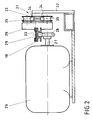
- Fig. 2 einen Teil-Querschnitt des Antriebs des Bajonetts der Maschine nach Fig. 1.
- Fig. 1 is a side view of a pallet strapping machine and
- FIG. 2 shows a partial cross section of the drive of the bayonet of the machine according to FIG. 1.
Zu einer insgesamt mit 10 bezeichneten Paletten-Umreifungsmaschine gehören ein Portal 11 mit Pfosten 12 und 13 sowie einem Balken 14, das eigentliche Maschinen-Aggregat 15 und ein Bajonett 16.A pallet strapping machine, designated overall by 10, includes a
Das Portal 11 bildet mit seinen Pfosten 12, 13 und seinem Balken 14 in Verbindung mit einer nicht dargestellten Umreifungsmittel-Führungseinrichtung innerhalb des Aggregats 15 und mit dem Bajonett 16 einen um ein auf einer Palette 17 ruhendes Packgut 18 umlaufenden Kanal für ein insbsondere bandförmiges Umreifungsmittel aus, mit dem das Packgut 18 auf und mitsamt seiner Palette 17 eingeschnürt wird.The
Hierzu wird zunächst das palettierte Packgut 17/18 mittels einer mit 20 angedeuteten Transporteinrichtung wie Rollenförderer in das Portal eingefahren. Sodann fährt das bezüglich Fig. 1 rechts in Ruhestellung wartende Bajonett 16 unter der Palette 17 hindurch und dockt bei 21 am Pfosten 12 an. In üblicher Weise schießt das Aggregat nun das Umreifungsmittel in Umlaufrichtung 22 durch den Umreifungskanal 19, bis das vordere Ende des Umreifungsmittels in einen Verschlußkopf 23 des Aggregats 15 eingeführt ist und dort festgehalten wird. Jetzt verfährt das Aggregat 15 gegen das Packgut 18 in die gestrichelt dargestellte Lage 15', und das Umreifungsmittel wird sodann entgegen seiner Einschußrichtung zurückgezogen, somit aus dem Umreifungskanal herausgezogen und schließlich um das Packgut gestrafft. Die einander überlappenden Umreifungsmittelabschnitte werden letztlich im Verschlußkopf 23 fest miteinander verbunden, also in der Regel thermisch verschweißt.For this purpose, the palletized packaged
Das alles ist im Prinzip bekannt. Neu und erfindungswesentlich sind der Antrieb 24 für das Bajonett 16 bzw. der Antrieb 25 für das Aggregat 15, auch in Verbindung mit ihren Linearführungen 31 bzw. 38.In principle, all of this is known. The
Als Antriebsmotor für das Bajonett 16 dient ein Drehfeldmagnet 26. Auf seiner Welle 27 (Fig. 2) ist ein Ritzel 28 drehfest gelagert, das mit einer unter dem Bajonett 16 befestigten Zahnstange 29 kämmt. Mit 30 ist der Umreifungsmittelkanal im Bajonett 16 bezeichnet, das an einer sehr einfach ausgebildeten Linearführung 31 gelagert ist.A rotating
Die Linearführung 31 umfaßt eine von zwei auf dem Boden stehenden Stützen 32 getragene Schiene 33 mit Schienenköpfen 34 aus Rundstahlstäben, auf denen an Laufwagen 36 drehbar angebrachte Rollen 35 laufen. An den Laufwagen wiederum ist das Bajonett 16 befestigt. Wenn nun die Welle 27 des Drehfeldmagneten 26 rotiert, treibt das Ritzel 28 das an der beschriebenen Linearführung gelagerte Bajonett an und schiebt es je nach Drehrichtung entweder nach vorn oder zieht es zurück.The
Stellt sich dem Bajonett 16 ein Hindernis in den Weg, wird seine weitere Bewegung bei dem Aufprall ohne weiteres, also ohne besondere Schaltungsmaßnahmen gestoppt, weil der Drehfeldmagnet auch unter Spannung ohne Überlastungsgefahr festgehalten werden kann. Ein solches Hindernis kann ein menschlicher Körperteil ebenso sein wie eine gebrochene Palette oder ein fehlerhaft positioniertes Packstück. In jedem Falle wird eine Beschädigung eines die Bewegungsbahn des Bajonetts 16 behindernden Gegenstandes sicher vermieden.If there is an obstacle in the way of the
Ein ganz ähnlicher Antrieb ist für das Aggregat 15 vorgesehen, Dessen Drehfeldmagnet ist mit 37 und seine Linearführung mit 38 bezeichnet (fig. 1). Die Welle des Drehfeldmagneten 37 kämmt mit einer unter dem Aggregat 15 besfestigten Zahnstange. Die Linearführung 38 ist auf der Oberseite des Aggregates 15 angebracht. Dadurch, d.h. durch die räumliche Trennung von Antrieb und Führung, wird eine sehr stabile Lage des Aggregats 15 erreicht.A very similar drive is provided for the
Die Führungsschiene 39 ist bewegungseinheitlich mit dem Aggregat 15 verbunden, während die Rollen 40 an einer raumfest gehaltenen Konsole 41 gelagert sind.The
Claims (4)
- Machine for the hoop-casing of palletised packaged goods together with the pallet with a hoop-casing means, in particular a thermoplastic tape, the machine consisting essentially of a portal, a bayonet complementary to said portal and forming a continuous tape guide channel for the hoop-casing means, and an aggregate for holding, conveying and sealing the hoop-casing means, wherein both the bayonet and the aggregate are equipped with a respective drive motor and a linear guide for their substantially horizontal motion relative to the packaged goods and the portal, characterised by the use of a rotating field magnet (26; 37) as a drive motor for the bayonet (16) and/or the aggregate (15).
- Pallet hoop-casing machine according to claim 1, characterised in that a drive pinion (28), which meshes with a rack (29) fixed to the bayonet (16) or to the aggregate (15), is mounted on the shaft (27) of the rotating field magnet (26 and 37 respectively).
- Pallet hoop-casing machine according to claim 2, characterised in that the respective rack (28) is connected to bogie trucks (36) guided on a support rail (33) by means of rollers (35).
- Pallet hoop-casing machine according to claim 2, characterised in that the respective rotating field magnets (37) for driving the aggregate (25) and its linear guide (38) are disposed on opposite sides of the aggregate (15).
Applications Claiming Priority (2)
| Application Number | Priority Date | Filing Date | Title |
|---|---|---|---|
| DE4007931A DE4007931A1 (en) | 1990-03-13 | 1990-03-13 | PALLET STRAPPING MACHINE |
| DE4007931 | 1990-03-13 |
Publications (2)
| Publication Number | Publication Date |
|---|---|
| EP0446736A1 EP0446736A1 (en) | 1991-09-18 |
| EP0446736B1 true EP0446736B1 (en) | 1995-02-01 |
Family
ID=6402065
Family Applications (1)
| Application Number | Title | Priority Date | Filing Date |
|---|---|---|---|
| EP91103169A Expired - Lifetime EP0446736B1 (en) | 1990-03-13 | 1991-03-02 | Strapping machine for pallets |
Country Status (2)
| Country | Link |
|---|---|
| EP (1) | EP0446736B1 (en) |
| DE (2) | DE4007931A1 (en) |
Families Citing this family (7)
| Publication number | Priority date | Publication date | Assignee | Title |
|---|---|---|---|---|
| US5355786A (en) * | 1993-09-21 | 1994-10-18 | Signode Corporation | Strap guide for guiding strap through aligned openings in pallet stringers |
| BR112013033458B1 (en) * | 2011-07-04 | 2020-06-02 | Ecolean Ab | TRANSPORT UNIT AND METHOD FOR MANUFACTURING A TRANSPORT UNIT |
| CN103086002B (en) * | 2013-02-22 | 2014-12-10 | 杭州永创智能设备股份有限公司 | Machine core of packing machine |
| AT514165B1 (en) * | 2013-04-11 | 2015-09-15 | Klein Thomas | Method for strapping palletised goods |
| DE102019118307B4 (en) * | 2019-04-24 | 2025-10-09 | Mosca Gmbh | Method and device for strapping pallets |
| CN110342009B (en) * | 2019-08-16 | 2020-09-11 | 南京斯杩克机器人技术有限公司 | Automatic adjustment bundler for detonator boxing system and automatic adjustment bundler method |
| CN111907766A (en) * | 2020-08-04 | 2020-11-10 | 池州市新辰包装科技有限公司 | A single-head double-slot vertical baling system |
Family Cites Families (3)
| Publication number | Priority date | Publication date | Assignee | Title |
|---|---|---|---|---|
| US3899963A (en) * | 1973-12-11 | 1975-08-19 | Signode Corp | Articulated strap chute and guide means therefor |
| US3949662A (en) * | 1975-04-29 | 1976-04-13 | Fmc Corporation | Pallet strapper with projectable lance |
| DE3507091A1 (en) * | 1985-02-28 | 1986-08-28 | Kraftwerk Union AG, 4330 Mülheim | ARMATURE TO BLOCK A FLOW |
-
1990
- 1990-03-13 DE DE4007931A patent/DE4007931A1/en not_active Withdrawn
-
1991
- 1991-03-02 EP EP91103169A patent/EP0446736B1/en not_active Expired - Lifetime
- 1991-03-02 DE DE59104449T patent/DE59104449D1/en not_active Expired - Lifetime
Also Published As
| Publication number | Publication date |
|---|---|
| EP0446736A1 (en) | 1991-09-18 |
| DE59104449D1 (en) | 1995-03-16 |
| DE4007931A1 (en) | 1991-09-19 |
Similar Documents
| Publication | Publication Date | Title |
|---|---|---|
| EP1132321B1 (en) | Roller conveyor | |
| EP2616379B2 (en) | Current collector system, crane system, and method for advancing a current collector carriage to a power rail | |
| DE69208828T2 (en) | Device for wrapping ring-shaped objects | |
| EP1446315B1 (en) | Popular amusement device with switchable eddy-current brake | |
| EP0000877A1 (en) | Manipulator for positionning workpieces or other loads | |
| DE1580909A1 (en) | Transport system | |
| DE4317998C2 (en) | Injection molding unit for a plastic injection molding machine | |
| DE2208514A1 (en) | Linear motor with carriage | |
| EP0069239B1 (en) | Propulsion device for transporting oblong half-products | |
| DE2823327A1 (en) | DEVICE FOR REWINDING OR UNWINDING OF MATERIALS FOR TAPE-SHAPED MATERIAL HANDLING MACHINES | |
| DE2749187C2 (en) | Device for feeding, positioning and messages of profiles for tack welding the profiles to plates or the like. | |
| EP0446736A1 (en) | Strapping machine for pallets | |
| DE69603349T2 (en) | Device for handling winding rolls | |
| DE19539752C2 (en) | Tie-bar-less two-plate injection molding machine | |
| EP0321680B1 (en) | Device for removing articles | |
| EP0806349B1 (en) | Tensioning device | |
| DE2635437A1 (en) | WIRE DRAWING MACHINE | |
| EP0481323B1 (en) | Method for feeding a production machine with a precision centering and apparatus therefor | |
| WO2006114128A1 (en) | Method and device for taking up long winding material | |
| DE3225595A1 (en) | Conveying path | |
| EP0289784A1 (en) | Foil-enveloping machine | |
| DE1774717A1 (en) | Trailing cable system | |
| DE2915174A1 (en) | SORTING MACHINE FOR WORKPIECES | |
| DE2832991A1 (en) | CHAIN ELEVATOR FOR COUPLED VEHICLE GROUPS OF LIGHTING DEVICES | |
| DE19612563B4 (en) | Device for moving objects to be packed |
Legal Events
| Date | Code | Title | Description |
|---|---|---|---|
| PUAI | Public reference made under article 153(3) epc to a published international application that has entered the european phase |
Free format text: ORIGINAL CODE: 0009012 |
|
| AK | Designated contracting states |
Kind code of ref document: A1 Designated state(s): CH DE FR GB IT LI |
|
| 17P | Request for examination filed |
Effective date: 19911030 |
|
| 17Q | First examination report despatched |
Effective date: 19940722 |
|
| ITF | It: translation for a ep patent filed | ||
| GRAA | (expected) grant |
Free format text: ORIGINAL CODE: 0009210 |
|
| AK | Designated contracting states |
Kind code of ref document: B1 Designated state(s): CH DE FR GB IT LI |
|
| GBT | Gb: translation of ep patent filed (gb section 77(6)(a)/1977) |
Effective date: 19950126 |
|
| ET | Fr: translation filed | ||
| REF | Corresponds to: |
Ref document number: 59104449 Country of ref document: DE Date of ref document: 19950316 |
|
| PGFP | Annual fee paid to national office [announced via postgrant information from national office to epo] |
Ref country code: CH Payment date: 19950412 Year of fee payment: 5 |
|
| PLBE | No opposition filed within time limit |
Free format text: ORIGINAL CODE: 0009261 |
|
| STAA | Information on the status of an ep patent application or granted ep patent |
Free format text: STATUS: NO OPPOSITION FILED WITHIN TIME LIMIT |
|
| 26N | No opposition filed | ||
| PG25 | Lapsed in a contracting state [announced via postgrant information from national office to epo] |
Ref country code: CH Effective date: 19960331 Ref country code: LI Effective date: 19960331 |
|
| REG | Reference to a national code |
Ref country code: CH Ref legal event code: PL |
|
| REG | Reference to a national code |
Ref country code: GB Ref legal event code: IF02 |
|
| PGFP | Annual fee paid to national office [announced via postgrant information from national office to epo] |
Ref country code: FR Payment date: 20100406 Year of fee payment: 20 |
|
| PGFP | Annual fee paid to national office [announced via postgrant information from national office to epo] |
Ref country code: GB Payment date: 20100326 Year of fee payment: 20 |
|
| PGFP | Annual fee paid to national office [announced via postgrant information from national office to epo] |
Ref country code: DE Payment date: 20100329 Year of fee payment: 20 Ref country code: IT Payment date: 20100329 Year of fee payment: 20 |
|
| REG | Reference to a national code |
Ref country code: DE Ref legal event code: R071 Ref document number: 59104449 Country of ref document: DE |
|
| REG | Reference to a national code |
Ref country code: GB Ref legal event code: PE20 Expiry date: 20110301 |
|
| PG25 | Lapsed in a contracting state [announced via postgrant information from national office to epo] |
Ref country code: GB Free format text: LAPSE BECAUSE OF EXPIRATION OF PROTECTION Effective date: 20110301 |
|
| PG25 | Lapsed in a contracting state [announced via postgrant information from national office to epo] |
Ref country code: DE Free format text: LAPSE BECAUSE OF EXPIRATION OF PROTECTION Effective date: 20110302 |