EP0446741B1 - Befestigung einer Flüssigkeitszerstäubungslanze - Google Patents
Befestigung einer Flüssigkeitszerstäubungslanze Download PDFInfo
- Publication number
- EP0446741B1 EP0446741B1 EP91103177A EP91103177A EP0446741B1 EP 0446741 B1 EP0446741 B1 EP 0446741B1 EP 91103177 A EP91103177 A EP 91103177A EP 91103177 A EP91103177 A EP 91103177A EP 0446741 B1 EP0446741 B1 EP 0446741B1
- Authority
- EP
- European Patent Office
- Prior art keywords
- housing
- coupling
- hose
- lance
- sleeve
- Prior art date
- Legal status (The legal status is an assumption and is not a legal conclusion. Google has not performed a legal analysis and makes no representation as to the accuracy of the status listed.)
- Expired - Lifetime
Links
Images

Classifications
-
- B—PERFORMING OPERATIONS; TRANSPORTING
- B05—SPRAYING OR ATOMISING IN GENERAL; APPLYING FLUENT MATERIALS TO SURFACES, IN GENERAL
- B05B—SPRAYING APPARATUS; ATOMISING APPARATUS; NOZZLES
- B05B15/00—Details of spraying plant or spraying apparatus not otherwise provided for; Accessories
- B05B15/60—Arrangements for mounting, supporting or holding spraying apparatus
- B05B15/65—Mounting arrangements for fluid connection of the spraying apparatus or its outlets to flow conduits
Definitions
- the present invention relates to a system for attaching a lance with an outlet spray nozzle to a rigid body of a hand held liquid spray apparatus and particularly to attaching the lance inlet to a pump outlet in a housing. More particularly, the invention relates to such a system by which the pump outlet coupling within the housing is insulated from mechanically transferring the vibration of the pump and the pump housing to the rigid lance.
- the invention has particular application to a spray apparatus, known as a pressure washer for spraying a high pressure liquid, whose spray is strong enough to wash dirt off the side of a building or a car body.
- Some pressure washers are held in the user's hand. They include a pump housing containing a pump within the housing. The pump outlet is connected to dispense liquid at high pressure through the outlet of a spray lance that is rigidly connected to the pump housing.
- the rigid pump housing is held by an operator who aims the liquid outlet from the lance where the liquid is to be sprayed. It would be desirable to simply rigidly attach the lance to the pump housing.
- the pump, its outlet coupling and the housing for the pump typically vibrate during pump operation. Further, the spraying of liquid at high pressure from the lance outlet causes the lance and the whole hand held pressure washer to vibrate. Vibration of the pressure washer could make the user uncomfortable and could make the lance difficult to hold or control.
- An object of the invention is to provide a system for attaching a liquid spraying lance to a hand held housing containing a pump whose operation vibrates the pump housing.
- Another object is to mechanically insulate the pump housing from the lance to avoid the transfer of vibration.
- a further object of the invention is to provide such a system in which the lance can be easily attached to the pump housing.
- a pump housing contains a rigid body and supports a rapidly operating, high pressure, liquid pump which normally vibrates and in turn causes the housing in which the pump is disposed to vibrate.
- the housing includes the pump outlet which is at a fluid coupling which is fixed on and vibrates with the pump housing.
- the lance includes a stiff body that transmits liquid from an inlet to the lance to an outlet from the lance.
- the attachment system is disposed between the inlet end of the lance and an outlet section of the pump housing.
- the system includes a rigid sleeve that is to be coupled to the pump housing.
- a flexible hose extends through that rigid sleeve.
- the hose has an inlet that is separably coupled to the pump outlet coupling inside the pump housing.
- the hose has an outlet that is separably attached to a lance inlet coupling.
- the rigid sleeve surrounds at least an intermediate portion of the length of the hose.
- the sleeve itself has an inlet end portion respectively anchored inside the pump housing and an outlet portion attached rigidly to the inlet end of the body of the lance.
- the hose is sufficiently flexible and unrestrained in the sleeve as to absorb the vibration of the pump housing and particularly of the pump outlet coupling and not transmit it to the lance inlet, which substantially insulates the pump housing and the lance from vibration transfer.
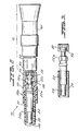
- Figs. 1 and 2 comprise a composite view of an attachment system for a liquid spray lance, and respectively comprise left-hand and right-hand portions of the composite view.
- Fig. 3 is a detail view of portions of the hose coupling of Fig. 2.
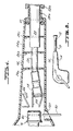
- Fig. 4 shows the structure of Fig. 1 during installation of the lance in the housing.
- Fig. 5 is a section view taken at arrows 5 in Fig. 1.
- Fig. 6 schematically shows a whole pressure washer including the lance.
- Figs. 1 and 2 together show an attachment system 10 for a liquid spray lance 12 (Fig. 2).
- the system 10 includes a rigid plastic or metal housing 14 which is integral with and extends forward from a pump housing 15. Toward the left or inlet end of the housing part 14, there is an outlet coupling 16 from a pump 17 (Fig. 6).
- the coupling 16 is rigidly and nonremovably supported inside of and therefore vibrates with the pump housing 14.
- the pump 17 normally vibrates as it operates at high speed and this vibrates the housing 14 even if the pump is supported in the housing by a shock-absorbing mounting.
- the pump outlet coupling 16 is intended to be separably coupled with an inlet coupling 18 at the left inlet end of a flexible hose 20.
- the illustrated outlet end of the hose 20 terminates in a coupling 22, which is shown in Fig. 3.
- Coupling 22 is connected to the lance 12, which includes an outlet nozzle 65 for spraying a pattern of liquid supplied through the hose 20.
- the outlet nozzle may be of the type disclosed in U.S. Patent No. 4,976,467 issued December 11, 1990, which is incorporated herein by reference.
- a relatively rigid sleeve 24 Surrounding an intermediate portion of the flexible hose 20 is a relatively rigid sleeve 24, made of ABS or PVC plastic, for example.
- the left or inlet end portion 24a of the sleeve 24 is anchored inside the housing 14 by internal housing panels 26a, 26b and 26c which are each slotted to snugly surround respective areas of the sleeve 24.
- the gasket 27 closes the entrance end of the housing 14 and also supports the sleeve portion 24a.
- a bolt extension 28a is molded integrally with the housing 14 and extends to the right or outlet end of the pump housing 14. The bolt surrounds and is coaxial with the sleeve 24.
- a hexogonal profile nut 28b is threaded onto the bolt 28a during assembly to additionally anchor the left sleeve portion 24a.
- the pump outlet coupling 16 supplies liquid at high pressure to the lance 12 via the hose end couplings 18 at the left and 22 at the right.
- the couplings 16, 18 and 22 should be rated, for example, to handle 2400 p.s.i. (170 bar), of water pressure.
- the right or outlet end portion 24b of the rigid sleeve 24 is anchored to the hose outlet coupling 22 with the aid of a surrounding sleeve 30 of rigid plastic.
- the sleeve 30 has a portion 30b, which surrounds the right outlet end of the sleeve portion 24b and is adhered to it, preferably by welding of plastic material.
- the sleeve 30 extends axially out to snugly and matingly surround a hexagonally faceted nut portion 22a of the coupling 22.
- Past nut portion 22a the sleeve 30 extends radially inwardly at its portion 30a toward a reduced diameter portion 22b of the coupling 22 located to the right of the faceted portion 22a.
- the hose 20 is sufficiently flexible and is sufficiently unrestrained, that is, it is free of restraint from the surrounding sleeve 24, so that vibration of the coupling 16 is dissipated in the flexible hose 20.
- the flexible hose 20 is unrestrained in that the portion of the hose 20 to the left of the left portion 24a of the sleeve 24 is unsheathed, and a clearance 40 is provided between the outer diameter of the hose 20 and the inner diameter of the sheath 24.
- inclined guide flanges 45 are formed inside the housing 14 axially outward of the pump coupling 16, surrounding the hose coupling 18 and converging inwardly toward the left toward pump outlet coupling 16.
- the guide flanges 45 guide the hose inlet coupling 18 into engagement with the housing coupling 16 when the flexible hose 20, only partially sheathed and not there guided by the sleeve 24, is inserted into the housing 14. After insertion, the sleeve 24 is anchored to the housing 14 by the bolt 28a and nut 28b.
- Figs. 2 and 3 illustrate the joining of the hose outlet coupling 22 to an inlet coupling 50 (Fig. 2) of the lance.
- the hose coupling 22 includes an internally threaded, externally profiled, e.g. hexagonal, cup nut 52 at its axially outward end which is tightened over an externally threaded bolt of a male coupling 50 (Fig. 2) of the lance 12.
- a disk 54 within the nut 52 of the coupling 22 has a central aperture (not shown) for permitting liquid flow.
- the disk 54 is separated from the left end of the coupling 50 by a washer 56.
- a nut clamping sleeve 58 surrounds the nut 52 of the hose coupling 22.
- the sleeve 58 is internally profiled to match the external profile of the nut 52, and the sleeve is sufficiently large (e.g., over about one inch in diameter) as to enable manual tightening of the nut 52 onto the lance coupling 50 through turning of the sleeve 58.
- a marker 60 on the lance 12 is brought into alignment with a corresponding marker (not shown) on the sleeve 58.
- the nozzle 65 of the lance 12 is rotatable with respect to the lance coupling 50, as further described in the above-referenced, copending application, and the aligned markers indicate the selected nozzle spray outlet of the nozzle 65.
- housing coupling 16 includes a cup shaped coupling part 80 with an internal cylindrical space for receiving cylindrical end part 82 of the hose coupling 18.
- the couplings 16 and 18 are sealed to each other with an O-ring 84 received within a groove 86 in the periphery of the cylindrical coupling part 82.
- Mechanical securement of the inserted hose coupling 18 to the housing coupling 16 is achieved, for example, by a retaining pin 90.
- the retaining pin 90 has two parallel arms 90a and 90b.
- Arm 90a passes first through a lower aperture 92 in the housing coupling part 80, then through circumferential groove 95 in the hose coupling part 82, and finally through an upper aperture 96 in the housing coupling part 80.
- Arms 90a and 90b are symmetrically coupled to the housing and hose couplings 16 and 18.
- Each of arms 90a and 90b contains a detent (e.g. 98) and these are cooperatively pressed toward each other by a resilient self bias of the retaining pin 90, and engage the bottom of groove 95, defined by the outer circumference of hose coupling part 100.
- a user inserts the hose coupling 18 into the pump coupling 16, with the aid of the guide flanges 45 as described above. Once they are engaged, the user then inserts the retaining 90 pin into the joined couplings 16 and 18 via an access port 102 at the underside of the housing 14.
- the nut 28b on the lance sleeve 24 is tightened onto the bolt 28a on the housing 14, which prevents extraction of the sleeve 24 from the housing 14. Removal of the lance from the housing requires reversing the foregoing steps.
- the foregoing describes an attachment system for a liquid handling lance, in which a vibratable coupling contained within a housing is substantially insulated from transferring vibration to the lance.
- the lance further, can be easily attached to the associated pump housing.
Landscapes
- Containers And Packaging Bodies Having A Special Means To Remove Contents (AREA)
- Nozzles (AREA)
- Structures Of Non-Positive Displacement Pumps (AREA)
- Special Spraying Apparatus (AREA)
- Details Or Accessories Of Spraying Plant Or Apparatus (AREA)
Claims (8)
- Befestigungssystem für eine Flüssigkeitssprühlanze, umfassend:
ein Pumpengehäuse (14) mit einer Pumpenauslaßkupplung (16), die bei Betrieb der Pumpe (17) zusammen mit dem Gehäuse (14) vibriert;
eine Sprühlanze (12), die am Gehäuse (14) an einer Stelle befestigbar ist, welche sich in einem Abstand von der Pumpenauslaßkupplung (16) befindet, wobei die Lanze (12) eine Flüssigkeitseinlaßkupplung (50) zum Herstellen einer leitenden Verbindung mit der Pumpenauslaßkupplung (16) aufweist;
wobei das Befestigungssystem (10) die folgenden Elemente aufweist:
eine Buchse (24) mit einem ersten und einem zweiten Endbereich, die jeweils am Gehäuse (14) bzw. an der Lanze (12) verankert und jeweils einzeln und hiervon abnehmbar sind;
einen Schlauch (20), der sich durch die Buchse (24) hindurch erstreckt, und der einen Zwischenbereich aufweist; an einander gegenüberliegenden Enden des Schlauches sind eine Schlaucheinlaßkupplung (18) und eine Schlauchauslaßkupplung (22) vorgesehen zur jeweiligen abnehmbaren Verbindung mit der Pumpenauslaßkupplung (16) und der Lanzeneinlaßkupplung (50);
die Buchse (24) ist relativ zum Zwischenbereich des Schlauches (20) starr, während der Zwischenbereich des Schlauches (20) genügend flexibel und frei ist, um das Gehäuse (14) und die Pumpenauslaßkupplung (16) im wesentlichen zu isolieren gegen Übertragung von Vibration zur Lanzeneinlaßkupplung (50). - Befestigungssystem nach Anspruch 1, wobei das Gehäuse (14) Innenführungen (45) zum Führen der Schlaucheinlaßkupplung (18) in Eingriff mit der Pumpenauslaßkupplung (16) aufweist.
- Befestigungssystem nach Anspruch 2, weiterhin umfassend von Hand betätigbare Mittel (90) an der Pumpenauslaßkupplung (16) zum Zusammenhalten der Schlaucheinlaßkupplung (18) und der Pumpenauslaßkupplung (16).
- Befestigungssystem nach Anspruch 1, wobei die Schlauchauslaßkupplung (22) und die Lanzeneinlaßkupplung (15) jeweils Gewindeteile (52, 50) aufweisen, die diese Kupplungen durch Verschraubung zusammenhalten.
- Befestigungssystem nach Anspruch 4, wobei eines der Gewindeteile eine Mutter (52) sowie einen Aktuator (58) umfaßt, der die Mutter umgibt und dahingehend erfaßt, daß die Mutter beim Verdrehen des Aktuators bewegt wird, um ein Anziehen der Mutter von Hand zu ermöglichen.
- Befestigungssystem nach Anspruch 5, wobei die Mutter (52) an der Schlauchauslaßkupplung (16) gebildet ist, und der Aktuator (58) eine die Mutter umgebende Aktuatorbuchse umfaßt, und wobei die Buchse ein Innenprofil entsprechend dem Profil der Aktuatormutter aufweist.
- Befestigungssystem nach Anspruch 1, umfassend Verankerungsmittel (26a, 26b, 26c, 28a, 28b) zum Verankern des ersten Endbereiches der Buchse (24) am Gehäuse (14).
- Befestigungssystem nach Anspruch 7, wobei das Verankerungsmittel einen Gewindebolzen (28a) umfaßt, der die Buchse (24) umgibt und koaxial zu dieser angeordnet ist, und der am Ende des Gehäuses (14) angeordnet ist, durch welche die Buchse (24) gegen die Lanze (12) vorsteht, ferner mit einer Mutter (28), die den Bolzen (28a) umgibt und den Bolzen (28a) am Gehäuse (14) verriegelt und damit die Buchse (24) am Gehäuse (14) sichert.
Applications Claiming Priority (2)
| Application Number | Priority Date | Filing Date | Title |
|---|---|---|---|
| US07/494,751 US5004160A (en) | 1990-03-16 | 1990-03-16 | Attachment system for liquid spray lance |
| US494751 | 1990-03-16 |
Publications (3)
| Publication Number | Publication Date |
|---|---|
| EP0446741A2 EP0446741A2 (de) | 1991-09-18 |
| EP0446741A3 EP0446741A3 (en) | 1991-11-27 |
| EP0446741B1 true EP0446741B1 (de) | 1993-06-16 |
Family
ID=23965815
Family Applications (1)
| Application Number | Title | Priority Date | Filing Date |
|---|---|---|---|
| EP91103177A Expired - Lifetime EP0446741B1 (de) | 1990-03-16 | 1991-03-02 | Befestigung einer Flüssigkeitszerstäubungslanze |
Country Status (5)
| Country | Link |
|---|---|
| US (1) | US5004160A (de) |
| EP (1) | EP0446741B1 (de) |
| AU (1) | AU634941B2 (de) |
| CA (1) | CA2038365A1 (de) |
| DE (1) | DE69100117T2 (de) |
Families Citing this family (3)
| Publication number | Priority date | Publication date | Assignee | Title |
|---|---|---|---|---|
| US8444068B2 (en) | 2005-10-26 | 2013-05-21 | Techtronic Outdoor Products Technology Limited | Dual flow pressure washer |
| US7854398B2 (en) * | 2005-10-26 | 2010-12-21 | Techtronic Outdoor Products Technology Limited | Hand held pressure washer |
| US8425203B2 (en) * | 2008-04-25 | 2013-04-23 | Techtronic Outdoor Products Technology Limited | Portable pressure washer system |
Family Cites Families (8)
| Publication number | Priority date | Publication date | Assignee | Title |
|---|---|---|---|---|
| DE1960369A1 (de) * | 1969-12-02 | 1971-06-09 | Siemens Ag | Vorrichtung zur Daempfung der Pulsation einer stroemenden Fluessigkeit |
| CH580987A5 (de) * | 1974-11-05 | 1976-10-29 | Krebs Theo Ag | |
| US4009988A (en) * | 1975-12-29 | 1977-03-01 | Lincoln Brass Works, Inc. | Gas valve and mixing tube assembly for gas burner |
| SU731166A1 (ru) * | 1978-02-13 | 1980-04-30 | Уфимский авиационный институт им. Орджоникидзе | Гибкий многослойный рукав |
| US4285534A (en) * | 1979-12-28 | 1981-08-25 | Nichirin Rubber Industrial Co., Ltd. | Pulsation-absorbing flexible pipe for pressure fluid device |
| US4416475A (en) * | 1982-12-09 | 1983-11-22 | Tarrant Manufacturing Company | Flexible coupling |
| DE8710738U1 (de) * | 1986-06-07 | 1987-12-10 | Mitsuba Electric Mfg. Co., Ltd., Kiryu, Gumma | Pulsierungsschutzelement für eine Pumpe |
| US4795100A (en) * | 1987-09-16 | 1989-01-03 | Purtell Rufus J | Conservation irrigation |
-
1990
- 1990-03-16 US US07/494,751 patent/US5004160A/en not_active Expired - Fee Related
-
1991
- 1991-03-02 DE DE91103177T patent/DE69100117T2/de not_active Expired - Fee Related
- 1991-03-02 EP EP91103177A patent/EP0446741B1/de not_active Expired - Lifetime
- 1991-03-15 CA CA002038365A patent/CA2038365A1/en not_active Abandoned
- 1991-03-15 AU AU73548/91A patent/AU634941B2/en not_active Ceased
Non-Patent Citations (1)
| Title |
|---|
| HEATING/PIPING/AIR CONDITIONING vol. 57, no. 1, January 1985, STAMFORD, CONNECTICUT, USA pages 111 - 115; LYLE F. YERGES: '"noise control in plumbing systems" *page 113, middle column, line 58 right column, line 38* * |
Also Published As
| Publication number | Publication date |
|---|---|
| CA2038365A1 (en) | 1991-09-17 |
| DE69100117T2 (de) | 1993-09-30 |
| US5004160A (en) | 1991-04-02 |
| EP0446741A2 (de) | 1991-09-18 |
| EP0446741A3 (en) | 1991-11-27 |
| AU634941B2 (en) | 1993-03-04 |
| AU7354891A (en) | 1991-09-19 |
| DE69100117D1 (de) | 1993-07-22 |
Similar Documents
| Publication | Publication Date | Title |
|---|---|---|
| US12171536B2 (en) | Swivel hose coupling with outer grip | |
| US6820291B1 (en) | Faucet assembly with easy-install pre-rinse unit mechanism | |
| US5788160A (en) | Steam atomizer attachment for shower | |
| CA2273727A1 (en) | Pullout faucet wand joint | |
| US6113006A (en) | Snap together window washer nozzle | |
| EP0449045A2 (de) | Vorrichtung zum lösbaren Verbinden einer Spritzeinheit, die mit einer durch einen Abzug angetriebenen Pumpe versehen ist, mit einem Handbehälterhals | |
| CA2188917A1 (en) | Automatic Transmission Cooler Flushing Device | |
| CA2124670A1 (en) | Lawn and Garden Sprayer with Hose Compression Connector | |
| EP0446741B1 (de) | Befestigung einer Flüssigkeitszerstäubungslanze | |
| JPH0726635Y2 (ja) | シャワーヘッド用接続具 | |
| US4639018A (en) | Joint for a water-carrying pipe system | |
| CA2361365C (en) | Fitting with fastening device | |
| US3843059A (en) | Device for positioning irrigation pipes and attaching risers thereto | |
| US6109535A (en) | Corrosion resistant irrigation machine | |
| EP4255170B1 (de) | Fluidverteiler | |
| CZ16802U1 (cs) | Ovládací zarízení, zejména zemní souprava | |
| US20040262916A1 (en) | Vessel outlet swivel assembly | |
| US6386465B1 (en) | Gun | |
| US7438240B2 (en) | Hand-held sprayer for hose rollers | |
| EP0908091B1 (de) | Zitzengummi für Zitzenbecher zum Melken von Tieren | |
| EP0885661A3 (de) | Sprühpistole mit Schnellkupplung | |
| WO2002061323A1 (en) | Hose coupling | |
| EP0484308B1 (de) | Deckelflansch | |
| JPS629971Y2 (de) | ||
| AU734215B2 (en) | A gun |
Legal Events
| Date | Code | Title | Description |
|---|---|---|---|
| PUAI | Public reference made under article 153(3) epc to a published international application that has entered the european phase |
Free format text: ORIGINAL CODE: 0009012 |
|
| AK | Designated contracting states |
Kind code of ref document: A2 Designated state(s): DE FR GB IT NL |
|
| PUAL | Search report despatched |
Free format text: ORIGINAL CODE: 0009013 |
|
| AK | Designated contracting states |
Kind code of ref document: A3 Designated state(s): DE FR GB IT NL |
|
| 17P | Request for examination filed |
Effective date: 19920507 |
|
| 17Q | First examination report despatched |
Effective date: 19921112 |
|
| GRAA | (expected) grant |
Free format text: ORIGINAL CODE: 0009210 |
|
| AK | Designated contracting states |
Kind code of ref document: B1 Designated state(s): DE FR GB IT NL |
|
| PG25 | Lapsed in a contracting state [announced via postgrant information from national office to epo] |
Ref country code: NL Effective date: 19930616 |
|
| REF | Corresponds to: |
Ref document number: 69100117 Country of ref document: DE Date of ref document: 19930722 |
|
| ET | Fr: translation filed | ||
| ITF | It: translation for a ep patent filed | ||
| NLV1 | Nl: lapsed or annulled due to failure to fulfill the requirements of art. 29p and 29m of the patents act | ||
| PLBE | No opposition filed within time limit |
Free format text: ORIGINAL CODE: 0009261 |
|
| STAA | Information on the status of an ep patent application or granted ep patent |
Free format text: STATUS: NO OPPOSITION FILED WITHIN TIME LIMIT |
|
| 26N | No opposition filed | ||
| PGFP | Annual fee paid to national office [announced via postgrant information from national office to epo] |
Ref country code: GB Payment date: 19950220 Year of fee payment: 5 |
|
| PGFP | Annual fee paid to national office [announced via postgrant information from national office to epo] |
Ref country code: DE Payment date: 19950222 Year of fee payment: 5 |
|
| PGFP | Annual fee paid to national office [announced via postgrant information from national office to epo] |
Ref country code: FR Payment date: 19950309 Year of fee payment: 5 |
|
| PG25 | Lapsed in a contracting state [announced via postgrant information from national office to epo] |
Ref country code: GB Effective date: 19960302 |
|
| GBPC | Gb: european patent ceased through non-payment of renewal fee |
Effective date: 19960302 |
|
| PG25 | Lapsed in a contracting state [announced via postgrant information from national office to epo] |
Ref country code: FR Effective date: 19961129 |
|
| PG25 | Lapsed in a contracting state [announced via postgrant information from national office to epo] |
Ref country code: DE Effective date: 19961203 |
|
| REG | Reference to a national code |
Ref country code: FR Ref legal event code: ST |
|
| PG25 | Lapsed in a contracting state [announced via postgrant information from national office to epo] |
Ref country code: IT Free format text: LAPSE BECAUSE OF NON-PAYMENT OF DUE FEES;WARNING: LAPSES OF ITALIAN PATENTS WITH EFFECTIVE DATE BEFORE 2007 MAY HAVE OCCURRED AT ANY TIME BEFORE 2007. THE CORRECT EFFECTIVE DATE MAY BE DIFFERENT FROM THE ONE RECORDED. Effective date: 20050302 |