EP0446871A1 - ProcÀ©dé et dispositif pour meuler et/ou affûter le tranchant d'un outil de coupe - Google Patents
ProcÀ©dé et dispositif pour meuler et/ou affûter le tranchant d'un outil de coupe Download PDFInfo
- Publication number
- EP0446871A1 EP0446871A1 EP91103761A EP91103761A EP0446871A1 EP 0446871 A1 EP0446871 A1 EP 0446871A1 EP 91103761 A EP91103761 A EP 91103761A EP 91103761 A EP91103761 A EP 91103761A EP 0446871 A1 EP0446871 A1 EP 0446871A1
- Authority
- EP
- European Patent Office
- Prior art keywords
- grinding
- disc
- sharpening
- paste
- tool
- Prior art date
- Legal status (The legal status is an assumption and is not a legal conclusion. Google has not performed a legal analysis and makes no representation as to the accuracy of the status listed.)
- Withdrawn
Links
Images

Classifications
-
- B—PERFORMING OPERATIONS; TRANSPORTING
- B24—GRINDING; POLISHING
- B24B—MACHINES, DEVICES, OR PROCESSES FOR GRINDING OR POLISHING; DRESSING OR CONDITIONING OF ABRADING SURFACES; FEEDING OF GRINDING, POLISHING, OR LAPPING AGENTS
- B24B3/00—Sharpening cutting edges, e.g. of tools; Accessories therefor, e.g. for holding the tools
- B24B3/36—Sharpening cutting edges, e.g. of tools; Accessories therefor, e.g. for holding the tools of cutting blades
Definitions
- the invention relates to a method for grinding, sharpening, polishing and the like.
- the cutting edge of a material processing tool in particular a woodworking tool, such as carving chisels and the like, according to the preamble of claim 1.
- the invention also relates to a device provided for carrying out this method according to the preamble of claim 4.
- the invention is therefore based on the object, in order to eliminate the disadvantages described, to design the method and the device of the generic type in such a way that material processing tools of different types and shapes, in particular woodworking tools, such as carving chisels and the like, are safe, effective and quick even by inexperienced persons can be ground or sharpened.
- a grinding, sharpening or polishing paste of a special composition is applied to the circumference of a rotating disc and then the cutting edge of the tool to be ground or sharpened is applied with its bevel at an acute angle or tangentially to the circumference of the disc in its direction of rotation as well as kept in contact with such a pressure that the applied paste liquefies due to the resulting frictional heat and abrasive particles stored therein cause the grinding, sharpening or polishing process.
- the device according to the invention has at least one rotatable disc which is seated on a motor-driven axis and on the disc periphery of which a thin layer of grinding, sharpening or polishing paste is applied, which has grinding particles embedded in meltable binders.
- two disks are used in the device according to the invention, which are fastened at a distance from one another on a common drive shaft driven by a motor, either on both sides of the motor or jointly on one motor side.
- This has the advantage that even with tools to be ground with a broad cutting edge, there is no obstruction by the respective neighboring disk. If such an embodiment of the device according to the invention is used with two disks fastened at a distance from one another on a drive axle, one disk is used exclusively for grinding or sharpening tools with straight cutting edges, while the other disk is only used for grinding or sharpening Tools with hollowed or otherwise shaped cutting edges is used.
- each disk which is seated in the manner mentioned on a carrier for example on a shaft, axis or the like and is driven by a motor, can be used for grinding, sharpening, polishing and the like.
- tools of all kinds are used, and preferably of those tools which are used for processing wood and in particular consist of carved chisels.
- the area of application of the respective wheel is independent of the profile of the tool to be ground or sharpened.
- the disks can be manufactured on a fiber basis, in particular on a textile fiber basis, the individual textile fibers being oriented in such a way that the disk is only very little worn.
- each disc is provided with additives which prevent the disc from deforming during the grinding and sharpening process.
- Each disc is preferably provided with further additives which support, improve and accompany the effect of the grinding, sharpening or polishing paste applied to the disc circumference in a thin layer.
- the method according to the invention takes place under thermal or thermoelastic conditions. Based on the fact that the disc is operated at speeds between approximately 500 and 6,000 rpm depending on the selected diameter, the application paste of a special composition is applied to the disc that is running. The temperature and the cooling effect of the composition of the application paste are matched to the respective disc of the device. If a small amount of grinding and sharpening paste has been applied to the circumference of the rotating disc by pressing it on, the tool to be ground or sharpened is pressed on at the desired angle. The resulting friction creates a temperature of the materials involved between about 75 and 150 o C.
- the grinding and sharpening paste is liquefied, so that the abrasive particles stored therein are released and mixed intensively with the molten binder of the grinding and sharpening paste.
- the released abrasive particles then remove the material from the tool cutting edge in the desired manner, the rotating disc easily adapting to the respective cutting edge shape of the tool in the temperature range mentioned.
- the binder used for the grinding and sharpening paste has such a composition or is designed such that it serves both as a lubricant and as a coolant during the grinding and sharpening process.
- the tool cutting edge cannot anneal and that the ground bevel Tool cutting edge always remains perfectly formed, ie has no humps or bale shapes. This also ensures that the desired or required grinding angle or cutting edge angle is always completely retained. Reworking on the opposite side of the cutting edge, ie on the inside of the tool cutting edge, is not necessary. It is therefore sufficient to press the cutting edge on the rotating disc for a certain short period of time in order to grind or sharpen the tool, and then to clean the tool, after which it is immediately ready for use.
- the cutting edge quality corresponds to that of a razor. It is also particularly advantageous that no burrs are formed on the tool cutting edge.
- the disk is preferably heated before the grinding and sharpening process is carried out, which can be done in a simple manner by pressing on lubricating paper.
- This measure results in further advantages, which include consist in the fact that the disc remains as new, perfectly clean and completely round, so that no undesirable vibrations occur during the rotation of the disc. This also prevents a selective warming up of the disk when grinding and sharpening especially small-sized tools. In addition, it is avoided from the outset that irregular wear of the pane, which does not occur from the outset, can have a negative effect.
- grinding and sharpening paste is again applied to the circumference of the rotating disk and the grinding or sharpening process is carried out again. The more material is removed from the tool cutting edge, the more grinding and sharpening paste is added.
- the grinding and sharpening method according to the invention has the essential advantage that the machined chamfer of the tool cutting edge has no crown, so that the regrinding or regrinding that may be required later can also be carried out very gently. This also has the consequence that the material consumption of the tool cutting edge is considerably reduced.
- the device according to the invention has either a single grinding and sharpening disc or two discs of preferably different compositions, which are fastened at a predetermined distance, preferably at a distance of approximately 20 to 25 mm, to a common drive shaft of a motor.
- the disks can of course also be arranged on both sides of the engine.
- the then liquid mass forms a film between the wheel and the cutting edge.
- connection between the disc and the tool cutting edge takes place on the widest possible surface, and also in those places that do not come into direct contact with the surface of the disc; In a way, it forms a bridge over a cushion of molten binder mixed with steel particles and abrasives. A further transport of excess heat that arises is largely possible via this bridge, so that the paste thereby acts as a coolant.
- the binder of the paste thus serves as a means to prevent the temperature from rising by preventing the temperature from rising to dangerous values, and it can therefore also take on the function of cooling or temperature control in the broader sense.
- the steel particles rubbed off the cutting edge are mixed intensively with the abrasive particles in the paste.
- the liquefied paste is increasingly penetrated with abraded steel particles so that the activity of the abrasive particles is reduced to the same extent.
- the abrasion performance of the abrasive particles becomes ever lower until finally in the equilibrium state there is no more abrasion on the tool cutting edge.
- the original abrasion performance during the grinding process is then restored by adding paste. This paste is added until the desired ground shape of the cutting edge is achieved.
- the abraded steel particles can be Observe in the melted grinding paste on the inside of the cutting edge so that the paste looks slightly dark matt glossy.
- the mixture, distribution and quality of the abrasive particles is designed in such a way that an optimal material abrasion is guaranteed in a temperature range that does not impair the quality desired by the hardening during the grinding process. This also means that annealing can never take place.
- the qualitatively and quantitatively fine-tuned additive in the discs supports accompanies and promotes the performance of the applied grinding paste.
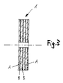
- the pane is designed as a composite pane which has a plurality of interconnected layers.
- the individual layers of the composite pane consist of so-called A layers, which absorb the application paste to be applied from the outside, and / or So-called B layers, which contain binders and at the same time carry grinding, sharpening or polishing bodies.
- the type of manufacture of the pane in no way limits its shape. In fact, it is possible that both the strength and elasticity, size and shape of the wheel and also the size or type of the integrated abrasive grain can be varied or adapted as desired.
- the type of binder of the composite pane can also be adapted to the technical requirements.
- the area of application of the wheel according to the invention extends to practically all working areas which have been covered by conventional grinding, sharpening or polishing wheels.
- the pane according to the invention can therefore be used in a suitable design for processing all metals, many plastics (including Plexiglas), glass, ceramics or even wood.
- the composite pane can be made only from A layers or only from B layers or alternately from A and B layers, wherein the layers can also have a different thickness.
- the A-layer which is preferably a textile carrier and consists of felt, fleece or the like, basically represents a rather passive layer during the grinding process, which serves to apply the layer to be applied to the outside of the disc circumference Take up grinding, sharpening or polishing paste (application paste).
- the A layer of the composite disc can be coated with a suitable agent, e.g. a coolant and / or a temperature control agent and / or a lubricant, etc., impregnated.
- a suitable agent e.g. a coolant and / or a temperature control agent and / or a lubricant, etc., impregnated.
- the shape stability or the desired degree of elasticity can be controlled for the entire composite pane.
- the A-layers of the composite pane can be open-pored or, depending on the technical requirements, can be designed to be tight and dimensionally stable.
- the thickness of the A layer of the composite pane can be adapted to the technical behavior of the pane in relation to the B layer. As the thickness increases, the A layer is more and more able to absorb a larger amount of the application paste to be applied externally.
- Various adhesive materials are also suitable as binders for the composite pane.
- the B-layer of the composite disc is an active layer that fulfills a double function, since this B-layer on the one hand performs a binding function and on the other hand carries grinding, sharpening or polishing bodies.
- the type of binding agent determines the elasticity of the entire composite pane, whereby the dimensional stability and hardness can also be controlled.
- the B layer of the composite disc can consist of felt, fabric, knitted fabric, nonwoven or a similar carrier material which is suitable for holding the binder, including the grinding, sharpening and polishing bodies mixed with it.
- the B layer is soaked in binder and coated on both sides.
- the binder or the adhesive material is mixed beforehand with a sufficient amount of abrasive, sharpening or polishing bodies.
- a layers and B layers are then alternately superimposed. As already mentioned, only A layers can be used and stacked to the desired composite pane.
- the composite pane has at least one A layer on the outside.
- the superimposed layers are then pressed for curing under pressure to the desired thickness or disk width.
- the binder used in each case penetrates with the mixed abrasives sufficiently in the pores of the A layers and hardens there.
- the grinding bodies which are internally integrated into the composite disc in this way thus already effect a corresponding grinding process from the inside.
- a temperature-dependent application paste is additionally applied to the running disc from the outside.
- the A-layers of the composite pane take up part of this application paste.
- the pressure of the tool to be sharpened on the disk results in a heating process so that the grinding, sharpening or polishing bodies of the application paste are optimally distributed in the adhesive contained in the paste.
- the material is removed from the tool to be sharpened completely safely for the hardened tool steel, and at a very high speed.
- the applied paste which contains fat in particular, greatly reduces the friction from the melting point.
- the temperature rise is reliably prevented except for heat-damaging values for the tool steel.
- the grinding, sharpening or polishing elements embedded in the B-layer binder support the abrasion process, which takes place in seconds.
- the cutting edge of the tool does not glow under any regular circumstances. It is always ready to cut again, provided the grain size is appropriately used.
- the composite material can be manufactured in any corresponding and adapted form. Natural or synthetic fibers, paper-like materials, cellulose, cotton, etc. can also be used as composites.
- two grinding and sharpening disks 1, 2 are provided, which are fastened in a rotationally fixed manner on a common axis 3 at a distance from one another, for example at a distance of approximately 20 to 25 mm.
- This axis 3 represents the drive axis of an electric motor 4, which is operated at a speed in the range between 500 and 6000 rpm depending on the respectively selected disc diameter and is fastened on a bearing bracket 5.
- This bearing bracket 5 also has, as can be seen from FIG. 2, at a sufficient distance from the disks 1, 2 rotating together with the axis 3, a support wall 6 on which the hand or hands of the user is held while the grinding is being carried out. and can support the sharpening process.
- the right-hand disk 2 is used exclusively for grinding or sharpening straight tool cutting edges, while the left-hand disk 1 is used for hollow or otherwise shaped tool cutting edges.
- the composition of the disks 1, 2 is such that they are manufactured on a fiber basis, the individual fibers being aligned in such a way that the respective disk material has only very little wear.
- the disks 1, 2 contain additives, on the one hand those which prevent deformation of the disk during the grinding and sharpening process, and on the other hand those which contain a grinding, sharpening or polishing paste to be applied in a thin layer during each grinding and sharpening process support, improve and accompany in their effect.
- the pane 1 shown is designed as a composite pane and consists of alternating A layers and B layers, the B layers being thinner than the A layers are.
- the A layers consist of an open-pore textile backing, for example felt or non-woven material
- the B layers consist of felt, woven fabric, knitted fabric, non-woven material, etc. and with a binder to which a sufficient amount of abrasive, sharpening or polishing agent has been added beforehand is soaked.
Landscapes
- Engineering & Computer Science (AREA)
- Mechanical Engineering (AREA)
- Finish Polishing, Edge Sharpening, And Grinding By Specific Grinding Devices (AREA)
- Polishing Bodies And Polishing Tools (AREA)
Applications Claiming Priority (2)
| Application Number | Priority Date | Filing Date | Title |
|---|---|---|---|
| DE4007844 | 1990-03-12 | ||
| DE19904007844 DE4007844A1 (de) | 1990-03-12 | 1990-03-12 | Verfahren und vorrichtung zum schleifen bzw. schaerfen der schneide eines materialbearbeitungswerkzeuges |
Publications (1)
| Publication Number | Publication Date |
|---|---|
| EP0446871A1 true EP0446871A1 (fr) | 1991-09-18 |
Family
ID=6402023
Family Applications (1)
| Application Number | Title | Priority Date | Filing Date |
|---|---|---|---|
| EP91103761A Withdrawn EP0446871A1 (fr) | 1990-03-12 | 1991-03-12 | ProcÀ©dé et dispositif pour meuler et/ou affûter le tranchant d'un outil de coupe |
Country Status (2)
| Country | Link |
|---|---|
| EP (1) | EP0446871A1 (fr) |
| DE (1) | DE4007844A1 (fr) |
Cited By (2)
| Publication number | Priority date | Publication date | Assignee | Title |
|---|---|---|---|---|
| EP0635334B1 (fr) * | 1993-07-22 | 2002-06-05 | TESSITURA LANDINI S.r.l. | Disque en textile impregné d'une résine contenant particules abrasives, procédé pour sa fabrication et procédé de rodage |
| ITUB20153151A1 (it) * | 2015-08-05 | 2017-02-05 | F Lli Milano Srl | Riavvivatrice filo diamantato a doppia mola |
Citations (5)
| Publication number | Priority date | Publication date | Assignee | Title |
|---|---|---|---|---|
| US3212167A (en) * | 1963-10-07 | 1965-10-19 | United States Steel Corp | Devices for shaping chasers and method of contouring the same |
| FR2036611A5 (fr) * | 1969-03-26 | 1970-12-24 | Giauque Robert | |
| DE2743585A1 (de) * | 1977-09-28 | 1979-03-29 | Klaus Dipl Ing Groove | Chleifkoerper o.dgl. fuer rundschleifmaschinen |
| DE8505164U1 (de) * | 1985-02-23 | 1986-06-19 | Koch, Kurt, 6751 Eulenbis | Schärfeinrichtung für Schnitzbeitel |
| DE8810148U1 (de) * | 1988-08-10 | 1988-09-29 | Gebr. Hegner KG Werkzeug- und Maschinenfabrik, 7730 Villingen-Schwenningen | Schärf- und Poliermaschine |
Family Cites Families (6)
| Publication number | Priority date | Publication date | Assignee | Title |
|---|---|---|---|---|
| DE106862C (fr) * | ||||
| DE571061C (de) * | 1933-02-23 | Klein Peter | Auswechselbare Schleifscheibe aus Filz fuer maschinell betriebene Hand- und Fusspflegeapparate | |
| DE558210C (de) * | 1930-03-12 | 1932-09-02 | Horn Und Klauenverwertung Alfr | Verfahren zum Auftragen von Schleif- und Poliermitteln auf rotierende Scheiben |
| DE1948273U (de) * | 1965-12-22 | 1966-10-20 | Rueggeberg August Fa | Schleifkoerper, insbesondere schleifscheibe, trennscheibe od. dgl. |
| DE2042393C3 (de) * | 1970-08-26 | 1975-03-13 | Fritz 7981 Heissen Knecht | Maschine zum Schleifen von Messern, insbesondere von Hand- und Kuttermessern |
| DE2931695C2 (de) * | 1979-08-04 | 1987-02-19 | Heinrich Lippert Gmbh, 7530 Pforzheim | Schleifkörper zum Vor- und Nachschleifen |
-
1990
- 1990-03-12 DE DE19904007844 patent/DE4007844A1/de not_active Withdrawn
-
1991
- 1991-03-12 EP EP91103761A patent/EP0446871A1/fr not_active Withdrawn
Patent Citations (5)
| Publication number | Priority date | Publication date | Assignee | Title |
|---|---|---|---|---|
| US3212167A (en) * | 1963-10-07 | 1965-10-19 | United States Steel Corp | Devices for shaping chasers and method of contouring the same |
| FR2036611A5 (fr) * | 1969-03-26 | 1970-12-24 | Giauque Robert | |
| DE2743585A1 (de) * | 1977-09-28 | 1979-03-29 | Klaus Dipl Ing Groove | Chleifkoerper o.dgl. fuer rundschleifmaschinen |
| DE8505164U1 (de) * | 1985-02-23 | 1986-06-19 | Koch, Kurt, 6751 Eulenbis | Schärfeinrichtung für Schnitzbeitel |
| DE8810148U1 (de) * | 1988-08-10 | 1988-09-29 | Gebr. Hegner KG Werkzeug- und Maschinenfabrik, 7730 Villingen-Schwenningen | Schärf- und Poliermaschine |
Cited By (2)
| Publication number | Priority date | Publication date | Assignee | Title |
|---|---|---|---|---|
| EP0635334B1 (fr) * | 1993-07-22 | 2002-06-05 | TESSITURA LANDINI S.r.l. | Disque en textile impregné d'une résine contenant particules abrasives, procédé pour sa fabrication et procédé de rodage |
| ITUB20153151A1 (it) * | 2015-08-05 | 2017-02-05 | F Lli Milano Srl | Riavvivatrice filo diamantato a doppia mola |
Also Published As
| Publication number | Publication date |
|---|---|
| DE4007844A1 (de) | 1991-09-19 |
Similar Documents
| Publication | Publication Date | Title |
|---|---|---|
| CH646628A5 (de) | Schleifkoerper fuer die metallbearbeitung. | |
| DE19511157A1 (de) | Abrichten von Schleifoberflächen aus kristallinem Bornitrid (CBN) | |
| DE3587769T2 (de) | Messerschleifgerät. | |
| DE602005001842T2 (de) | Schleifelement | |
| EP0048356B1 (fr) | Procédé pour le dressage des meules | |
| DE202012101515U1 (de) | Schleifmittel und Schleifwerkzeug | |
| EP1120198A2 (fr) | Outil de meulage, dispositif ainsi équipé et procédé d'usinage de pièces mettant en oeuvre cet outil | |
| DE2350405A1 (de) | Schleif- oder poliervorrichtung | |
| DE69211137T2 (de) | Mit einem Vielpunktschnittwerkzeug, planiertes, beschichtetes Schleifmittel | |
| DE2825852A1 (de) | Verfahren und werkzeug zum abrichten einer schleifscheibe | |
| DE2931695C2 (de) | Schleifkörper zum Vor- und Nachschleifen | |
| DE19736248A1 (de) | Ultraschall-Vibrations-Verbundschleifwerkzeug | |
| EP0446871A1 (fr) | ProcÀ©dé et dispositif pour meuler et/ou affûter le tranchant d'un outil de coupe | |
| EP4110552B1 (fr) | Outil de polissage | |
| DE602004006149T3 (de) | Schleifgerät, dessen Anwendung zum Schleifen von zylindrischen Gegenständen , Vorrichtung und Verfahren zum Schleifen von zylindrischen Gegenständen | |
| DE912057C (de) | Verfahren und Vorrichtung zum aufeinanderfolgenden Scharfschleifen und Feinstschleifen bzw. Laeppen von Drehmeisseln oder anderen Zerspanungswerkzeugen | |
| DE2348338C3 (de) | Aus Bindemittel und Schleifkorn bestehender Schleifkörper | |
| EP0906173B1 (fr) | Dispositif pour rectifier des vilebrequins ou pieces similaires | |
| DE3307599A1 (de) | Abrichteinrichtung | |
| DE10012919C1 (de) | Walze zum Polieren von Oberflächen und Verfahren zur Herstellung der Walze | |
| DD151607A5 (de) | Schleifkoerper fuer die metallbearbeitung | |
| DE3028702C2 (de) | Werkzeug zum Feinschärfen von Messerschneiden | |
| DE3314453A1 (de) | Verfahren und vorrichtung zum profilieren und/oder abrichten von schleifkoerpern | |
| DE4443074C1 (de) | Verfahren zur Herstellung von abrasiv belegten Einkegelscheiben, insbesondere Abrichtscheiben | |
| DE102020001283A1 (de) | Polierwerkzeug |
Legal Events
| Date | Code | Title | Description |
|---|---|---|---|
| PUAI | Public reference made under article 153(3) epc to a published international application that has entered the european phase |
Free format text: ORIGINAL CODE: 0009012 |
|
| AK | Designated contracting states |
Kind code of ref document: A1 Designated state(s): AT DE ES FR GB IT |
|
| 17P | Request for examination filed |
Effective date: 19920318 |
|
| 17Q | First examination report despatched |
Effective date: 19920623 |
|
| STAA | Information on the status of an ep patent application or granted ep patent |
Free format text: STATUS: THE APPLICATION IS DEEMED TO BE WITHDRAWN |
|
| 18D | Application deemed to be withdrawn |
Effective date: 19940611 |