EP0446946B1 - Endless film and heating apparatus using same - Google Patents
Endless film and heating apparatus using same Download PDFInfo
- Publication number
- EP0446946B1 EP0446946B1 EP91104047A EP91104047A EP0446946B1 EP 0446946 B1 EP0446946 B1 EP 0446946B1 EP 91104047 A EP91104047 A EP 91104047A EP 91104047 A EP91104047 A EP 91104047A EP 0446946 B1 EP0446946 B1 EP 0446946B1
- Authority
- EP
- European Patent Office
- Prior art keywords
- film
- rib
- hardness
- jis
- degrees
- Prior art date
- Legal status (The legal status is an assumption and is not a legal conclusion. Google has not performed a legal analysis and makes no representation as to the accuracy of the status listed.)
- Expired - Lifetime
Links
- 238000010438 heat treatment Methods 0.000 title claims description 5
- 239000000463 material Substances 0.000 claims description 54
- 229920001971 elastomer Polymers 0.000 claims description 21
- 239000007767 bonding agent Substances 0.000 claims description 14
- 239000000806 elastomer Substances 0.000 claims description 13
- 229920001169 thermoplastic Polymers 0.000 claims description 11
- 239000004416 thermosoftening plastic Substances 0.000 claims description 11
- 239000005060 rubber Substances 0.000 claims description 8
- 239000004642 Polyimide Substances 0.000 claims description 5
- 229920001721 polyimide Polymers 0.000 claims description 5
- 229920002943 EPDM rubber Polymers 0.000 claims 2
- 229920006311 Urethane elastomer Polymers 0.000 claims 2
- 239000000853 adhesive Substances 0.000 description 24
- 230000001070 adhesive effect Effects 0.000 description 24
- 229920002635 polyurethane Polymers 0.000 description 10
- 239000004814 polyurethane Substances 0.000 description 10
- 229920006332 epoxy adhesive Polymers 0.000 description 8
- 229920005989 resin Polymers 0.000 description 8
- 239000011347 resin Substances 0.000 description 8
- -1 polyethylene terephthalate Polymers 0.000 description 6
- 229920001343 polytetrafluoroethylene Polymers 0.000 description 5
- 239000004810 polytetrafluoroethylene Substances 0.000 description 5
- 238000002474 experimental method Methods 0.000 description 4
- 239000004695 Polyether sulfone Substances 0.000 description 3
- 229920006393 polyether sulfone Polymers 0.000 description 3
- PPBRXRYQALVLMV-UHFFFAOYSA-N Styrene Chemical compound C=CC1=CC=CC=C1 PPBRXRYQALVLMV-UHFFFAOYSA-N 0.000 description 2
- 229920001084 poly(chloroprene) Polymers 0.000 description 2
- 229920002725 thermoplastic elastomer Polymers 0.000 description 2
- OKTJSMMVPCPJKN-UHFFFAOYSA-N Carbon Chemical compound [C] OKTJSMMVPCPJKN-UHFFFAOYSA-N 0.000 description 1
- 239000004709 Chlorinated polyethylene Substances 0.000 description 1
- 229920001651 Cyanoacrylate Polymers 0.000 description 1
- 239000004593 Epoxy Substances 0.000 description 1
- JOYRKODLDBILNP-UHFFFAOYSA-N Ethyl urethane Chemical compound CCOC(N)=O JOYRKODLDBILNP-UHFFFAOYSA-N 0.000 description 1
- YCKRFDGAMUMZLT-UHFFFAOYSA-N Fluorine atom Chemical compound [F] YCKRFDGAMUMZLT-UHFFFAOYSA-N 0.000 description 1
- 239000004640 Melamine resin Substances 0.000 description 1
- 229920000877 Melamine resin Polymers 0.000 description 1
- 229920000459 Nitrile rubber Polymers 0.000 description 1
- 239000004696 Poly ether ether ketone Substances 0.000 description 1
- 239000004952 Polyamide Substances 0.000 description 1
- 239000004697 Polyetherimide Substances 0.000 description 1
- 239000004734 Polyphenylene sulfide Substances 0.000 description 1
- 150000001336 alkenes Chemical class 0.000 description 1
- XAGFODPZIPBFFR-UHFFFAOYSA-N aluminium Chemical compound [Al] XAGFODPZIPBFFR-UHFFFAOYSA-N 0.000 description 1
- 229910052782 aluminium Inorganic materials 0.000 description 1
- 125000003118 aryl group Chemical group 0.000 description 1
- 229920005549 butyl rubber Polymers 0.000 description 1
- 229910052799 carbon Inorganic materials 0.000 description 1
- 239000011248 coating agent Substances 0.000 description 1
- 238000000576 coating method Methods 0.000 description 1
- 230000001276 controlling effect Effects 0.000 description 1
- 238000001514 detection method Methods 0.000 description 1
- 238000007599 discharging Methods 0.000 description 1
- HQQADJVZYDDRJT-UHFFFAOYSA-N ethene;prop-1-ene Chemical group C=C.CC=C HQQADJVZYDDRJT-UHFFFAOYSA-N 0.000 description 1
- 239000005038 ethylene vinyl acetate Substances 0.000 description 1
- 229910052731 fluorine Inorganic materials 0.000 description 1
- 239000011737 fluorine Substances 0.000 description 1
- 229920003049 isoprene rubber Polymers 0.000 description 1
- 239000004973 liquid crystal related substance Substances 0.000 description 1
- 238000012986 modification Methods 0.000 description 1
- 230000004048 modification Effects 0.000 description 1
- JRZJOMJEPLMPRA-UHFFFAOYSA-N olefin Natural products CCCCCCCC=C JRZJOMJEPLMPRA-UHFFFAOYSA-N 0.000 description 1
- 239000005011 phenolic resin Substances 0.000 description 1
- 229920001200 poly(ethylene-vinyl acetate) Polymers 0.000 description 1
- 229920002492 poly(sulfone) Polymers 0.000 description 1
- 229920002647 polyamide Polymers 0.000 description 1
- 229920000728 polyester Polymers 0.000 description 1
- 239000004645 polyester resin Substances 0.000 description 1
- 229920001225 polyester resin Polymers 0.000 description 1
- 229920002530 polyetherether ketone Polymers 0.000 description 1
- 229920001601 polyetherimide Polymers 0.000 description 1
- 229920000139 polyethylene terephthalate Polymers 0.000 description 1
- 239000005020 polyethylene terephthalate Substances 0.000 description 1
- 229920000069 polyphenylene sulfide Polymers 0.000 description 1
- 230000001105 regulatory effect Effects 0.000 description 1
- 238000000926 separation method Methods 0.000 description 1
- 229920002379 silicone rubber Polymers 0.000 description 1
- 239000004945 silicone rubber Substances 0.000 description 1
- 229920003048 styrene butadiene rubber Polymers 0.000 description 1
- 229920001897 terpolymer Polymers 0.000 description 1
- 229940117958 vinyl acetate Drugs 0.000 description 1
- 125000000391 vinyl group Chemical group [H]C([*])=C([H])[H] 0.000 description 1
- 229920002554 vinyl polymer Polymers 0.000 description 1
- 238000010792 warming Methods 0.000 description 1
Images

Classifications
-
- G—PHYSICS
- G03—PHOTOGRAPHY; CINEMATOGRAPHY; ANALOGOUS TECHNIQUES USING WAVES OTHER THAN OPTICAL WAVES; ELECTROGRAPHY; HOLOGRAPHY
- G03G—ELECTROGRAPHY; ELECTROPHOTOGRAPHY; MAGNETOGRAPHY
- G03G15/00—Apparatus for electrographic processes using a charge pattern
- G03G15/20—Apparatus for electrographic processes using a charge pattern for fixing, e.g. by using heat
- G03G15/2003—Apparatus for electrographic processes using a charge pattern for fixing, e.g. by using heat using heat
- G03G15/2014—Apparatus for electrographic processes using a charge pattern for fixing, e.g. by using heat using heat using contact heat
- G03G15/2064—Apparatus for electrographic processes using a charge pattern for fixing, e.g. by using heat using heat using contact heat combined with pressure
-
- G—PHYSICS
- G03—PHOTOGRAPHY; CINEMATOGRAPHY; ANALOGOUS TECHNIQUES USING WAVES OTHER THAN OPTICAL WAVES; ELECTROGRAPHY; HOLOGRAPHY
- G03G—ELECTROGRAPHY; ELECTROPHOTOGRAPHY; MAGNETOGRAPHY
- G03G2215/00—Apparatus for electrophotographic processes
- G03G2215/20—Details of the fixing device or porcess
- G03G2215/2003—Structural features of the fixing device
- G03G2215/2016—Heating belt
-
- G—PHYSICS
- G03—PHOTOGRAPHY; CINEMATOGRAPHY; ANALOGOUS TECHNIQUES USING WAVES OTHER THAN OPTICAL WAVES; ELECTROGRAPHY; HOLOGRAPHY
- G03G—ELECTROGRAPHY; ELECTROPHOTOGRAPHY; MAGNETOGRAPHY
- G03G2215/00—Apparatus for electrophotographic processes
- G03G2215/20—Details of the fixing device or porcess
- G03G2215/2003—Structural features of the fixing device
- G03G2215/2016—Heating belt
- G03G2215/2035—Heating belt the fixing nip having a stationary belt support member opposing a pressure member
- G03G2215/2038—Heating belt the fixing nip having a stationary belt support member opposing a pressure member the belt further entrained around one or more rotating belt support members
Definitions
- the present invention relates to an endless belt and a heating apparatus using the same, usable with an image forming apparatus such as a copying machine or photoprinter to fix an unfixed image or to improve the surface property of the image.
- the recording material is passed through a nip formed between a heating roller and a pressing roller, that is, a heat-roller type is widely used.
- the heat-roller type fixing system involves a problem that the time required for warming the apparatus up to a predetermined temperature is long.
- the film tends to shift laterally, that is, shift in the direction perpendicular to the film travel.
- a rib or ribs are provided at a lateral end or ends to confine the lateral shifting tendency as suggested according EP-A-0310992.
- the use of the rib still involves problems.
- the curvature becomes locally small. If the rib is bonded on the film, the rib is peeled off the film where the curvature is small, or the rib does not deform in compliance with the curvature with the result of stress applied to the film beyond the tensile strength of the film with the result of tearing it.
- an endless film to which a rib extending parallel to a lateral end of said film and having a JIS (Japanese Industrial Standard) A hardness of not more than 100 degrees is bonded, the bonding agent after being cured having a JIS A hardness of not more than 100 degrees.
- JIS Japanese Industrial Standard
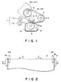
- Figure 1 is a sectional view of an image fixing apparatus according to an embodiment of the present invention.
- Figure 2 is a top plan view of the image fixing apparatus of Figure 1.
- Figure 3 is a sectional view of an image fixing apparatus according to another embodiment of the present invention.
- Figure 4 is a perspective view of the apparatus of Figure 3, as seen from upper right side.
- Figure 5 is a perspective view of the apparatus of Figure 3, as seen from left side.
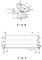
- Figure 6 is a sectional view of an image fixing apparatus according to a further embodiment of the present invention.
- Figure 7 is a perspective view of the apparatus of Figure 6, as seen from upper right side.
- the fixing apparatus comprises a low thermal capacity linear heater 1 which is stationary in use.
- the heater includes an aluminum base plate having a high thermal conductivity and an electric resistance material applied thereon. It generates heat upon power supply thereto.
- the resistance material is connected with an electric energy supply source at longitudinal opposite ends.
- the heater 1 is fixed by a low thermal conductivity insulating member (holder) 6 and a supporting member 7 having sufficient rigidity.
- the power supply is in the form of a pulse wave of DC 100 v with the period of 20 msec, for example.
- the temperature is detected by a temperature sensor, and the controlled pulse energy is supplied in accordance with the amount of energy emission. Generally, the pulsewidth ranges between 0.5 - 5 msec.
- a fixing film 2 moves in the direction indicated by an arrow B.
- the film comprises a heat-resistive resin having a thickness of approximately 20 microns, in the form of a thin endless film.
- the base member is preferably made of polyethylene terephthalate, polyphenylene sulfide, liquid crystal aromatic polyester resin, polyether ether ketone, polysulfone, polyether sulfone, polyether imide, polyimide or the like. From the standpoint of preventing the toner offset, it is preferable that the heat resistive resin base is coated with a thin parting layer of fluorinated resin such as polytetrafluoroethylene having increased electric conductivity by dispersing carbon or the like therein.
- the coating is outside the base material.
- the part or parts of the resin base at which a rib or ribs which will be described hereinafter are bonded are not coated with the parting layer, from the standpoint of increasing the bonding strength between the rib and the endless film.
- the total thickness of the film is preferably smaller than 50 microns.
- the ribs 3a and 3b are made of rubber or thermo-plastic elastomer material and are bonded to the film 2 with a bonding agent or adhesive material.
- the usable materials of the rib include styrene butadiene rubber, nitrile rubber, chloroprene rubber, ethylenepropylene terpolymer, butyl rubber, isoprene rubber, silicone rubber or another rubber material, and include styrene thermo-plastic elastomer, olefin thermoplastic elastomer, polychloride vinyl thermo-plastic elastomer, urethane thermo-plastic elastomer, polyester thermo-plastic elastomer, polyamide thermo-plastic elastomer, fluorine thermo-plastic elastomer, chlorinated polyethylene thermoplastic elastomer, ethylenepropylenediene tercopolymer (EPDM), or another thermo-plastic elastomer.
- styrene thermo-plastic elastomer olefin thermoplastic elastomer
- polychloride vinyl thermo-plastic elastomer polychloride vinyl thermo-plastic elastomer, ure
- the usable bonding materials include a rubber bonding agent such as neoprene or chloroprene bonding agent, melamine resin bonding agent, phenol resin bonding agent, epoxy bonding agent, vinylacetate bonding agent, ethylenevinylacetate bonding agent, cyanoacrylate bonding agent and polyurethane bonding agent.
- a rubber bonding agent such as neoprene or chloroprene bonding agent, melamine resin bonding agent, phenol resin bonding agent, epoxy bonding agent, vinylacetate bonding agent, ethylenevinylacetate bonding agent, cyanoacrylate bonding agent and polyurethane bonding agent.
- the fixing film 2 is stretched around a driving roller 4 and a follower roller 5 which cooperate with the heater 1 to constitute a film travel path.
- the fixing film 2 is stretched by urging the follower roller 5 in the direction of an arrow A, and is moved in the direction B by the driving roller 4.
- the pressing roller 9 is supported by unshown bearing to rotate following the film 2 travel. It urges the film 2 to the heater 1 with a total pressure of 4 - 7 kg, so that it is rotated in press-contact to the heater 1.
- FIG. 2 is a top plan view of the apparatus of Figure 1.
- Confining members 12A and 12B are provided along an outer periphery of the driving roller 4 at the insides of the ribs 3a and 3b to confine the ribs 3a and 3b. Even if the film 2 tends to laterally shift in a direction indicated by an arrow C, for example, the rib 3a abuts the confining member 12a, so that the lateral shift stops. On the contrary, if the film tends to shift in a direction D, the rib 3b is confined by the confining member 12b, so that the lateral shift in this direction stops.
- an unshown recording sheet is passed along an inlet guide 8 and is introduced into the nip formed between the film 2 and the pressing roller 9.
- the toner image on the recording material is heated and fused by the heat and the pressure provided by the heater 1 and the pressing roller 9, by which the toner image is fixed on the recording material.
- the recording material now having the fixed image is discharged to the outside of the apparatus by sheet discharging rollers 11 along a separation guide 10.
- Rib Polyurethane material having JIS A hardness of 80 degrees.
- Adhesive Epoxy adhesive having JIS A hardness of 86 degrees after being cured.
- the film was incorporated in the fixing apparatus of Figure 1, and the recording materials were continuously processed to fix the images thereon. As a result, it was confirmed that the lateral shift of the film was effectively prevented without peeling of the ribs and without tearing of the film.
- Rib Polyurethane material having JIS A hardness of 90 degrees.
- the film was incorporated in the fixing apparatus of Figure 1, and the recording materials were continuously processed to fix the images thereon. As a result, it was confirmed that the lateral shift of the film was effectively prevented without peeling of the ribs and without tearing of the film, similarly to Example 1.
- Rib Polyurethane material having JIS A hardness of 100 degrees.
- the film was incorporated in the fixing apparatus of Figure 1, and the recording materials were continuously processed to fix the images thereon. As a result, it was confirmed that the lateral shift of the film was effectively prevented without peeling of the ribs and without tearing of the film, similarly to Example 1.
- Rib EPDM material having JIS A hardness of 100 degrees.
- the film was incorporated in the fixing apparatus of Figure 1, and the recording materials were continuously processed to fix the images thereon. As a result, it was confirmed that the lateral shift of the film was effectively prevented without peeling of the ribs and without tearing of the film, similarly to Example 1.
- Rib Polyurethane material having JIS A hardness of 100 degrees.
- the film was incorporated in the fixing apparatus of Figure 1, and the recording materials were continuously processed to fix the images thereon. As a result, it was confirmed that the lateral shift of the film was effectively prevented without peeling of the ribs and without tearing of the film.
- Rib Polyurethane material having JIS A hardness of 110 degrees.
- Adhesive Epoxy adhesive having JIS A hardness of 86 degrees after being cured, as in Example 1.
- the film was incorporated in the fixing apparatus of Figure 1, and the recording materials were continuously processed to fix the images thereon.
- the rib or ribs were peeled off the film in several hours, with the result that the lateral shift was not controllable.
- Rib EPDM material having JIS A hardness of 110 degrees.
- the film was incorporated in the fixing apparatus of Figure 1, and the recording materials were continuously processed to fix the images thereon.
- the rib or ribs were peeled off the film in several hours, with the result that the lateral shift of the film was not controllable.
- Rib Polyurethane material having JIS A hardness of 110 degrees.
- the film was incorporated in the fixing apparatus of Figure 1, and the recording materials were continuously processed to fix the images thereon.
- the film was torn.
- the peeling of the rib and the tearing of the film can be prevented by using, as the material of the rib, rubber or thermo-plastic elastomer material having JIS A hardness of 100 degrees or less.
- the inventor has found that the hardness of the adhesive is significantly influential to the durability of the film. Experiments have been conducted with a variety of hardness of the adhesive.
- Rib Polyurethane material having JIS A hardness of 90 degrees.
- Adhesive Epoxy adhesive having JIS A hardness of 78 degrees after being cured.
- the film was incorporated in the fixing apparatus of Figure 1, and the recording materials were continuously processed to fix the images thereon. As a result, it was confirmed that the lateral shift of the film was effectively prevented without peeling of the ribs and without tearing of the film.
- Adhesive Epoxy adhesive having JIS A hardness of 92 degrees after being cured.
- the film was incorporated in the fixing apparatus of Figure 1, and the recording materials were continuously processed to fix the images thereon. As a result, it was confirmed that the lateral shift of the film as effectively prevented without peeling of the ribs and without tearing of the film.
- Adhesive Epoxy adhesive having JIS A hardness of 98 degrees after being cured.
- the film was incorporated in the fixing apparatus of Figure 1, and the recording materials were continuously processed to fix the images thereon. As a result, it was confirmed that the lateral shift of the film was effectively prevented without peeling of the ribs and without tearing of the film.
- Adhesive Polyurethane adhesive having JIS A hardness of 95 degrees after being cured.
- the film was incorporated in the fixing apparatus of Figure 1, and the recording materials were continuously processed to fix the images thereon. As a result, it was confirmed that the lateral shift of the film was effectively prevented without peeling of the ribs and without tearing of the film.
- Adhesive Epoxy adhesive having JIS A hardness of 98 degrees after being cured.
- the film was incorporated in the fixing apparatus of Figure 1, and the recording materials were continuously processed to fix the image thereon. As a result, it was confirmed that the lateral shift of the film was effectively prevented without peeling of the ribs and without tearing of the film.
- Adhesive Epoxy adhesive having JIS A hardness of 105 degrees after being cured.
- the film was incorporated in the fixing apparatus of Figure 1, and the recording materials were continuously processed to fix the images thereon.
- the rib or ribs were peeled off the film in several hours, with the result that the lateral shift of the film was not controllable.
- Adhesive Polyurethane adhesive having JIS A hardness of 110 degrees after being cured.
- the film as incorporated in the fixing apparatus of Figure 1, and the recording materials were continuously processed to fix the images thereon.
- the rib or ribs were peeled off the film in several hours, with the result that the lateral shift of the film was not controllable.
- Adhesive Epoxy adhesive having JIS A hardness of 105 degrees after being cured.
- the film was incorporated in the fixing apparatus of Figure 1, and the recording materials were continuously processed to fix the images thereon.
- the film was torn.
- the rib is made of a material having JIS A hardness of 100 degrees or less and if the adhesive used has a JIS A hardness of 100 degrees or less after being cured.
- Figure 3 is a sectional view of an image fixing apparatus of this embodiment wherein the lateral shift of the film is detected using the rib at the end of the film, in order to suppress the lateral shift of the film.
- Figure 4 is a perspective view of the apparatus of Figure 3, as seen from upper right side.
- Figure 5 is a right side view of the apparatus of Figure 3.
- a lever 16 functioning as an actuator for the sensor 15 is contacted to a part of the rib 22 on the film 21. If the film 21 is shifted laterally in the direction of an arrow E, the lever 16 rotates to actuate or deactuate the sensor.
- solenoids 17A and 17B are energized or deenergized, thus controlling the urging force applied by the urging means 13a and 13b. In this manner, the lateral shift direction can be changed to assure the control.
- the fixing film having the rib made of the material having JIS A hardness of 100 degrees or less, as in the embodiment of Figure 1, which is bonded thereto with an adhesive having a JIS A hardness of 100 degrees or less after being cured was effective, because the detection of the lateral shift of the film was assured without peeling of the rib and the tearing of the film.
- Figure 6 is a sectional view of an image fixing apparatus of another type wherein the rib is confined to prevent the lateral shifting of the film.
- the rib 32 is formed on an inside surface of the fixing film 31 and at one lateral end.
- Figure 7 is a perspective view of the apparatus of Figure 6, as seen from the film 31 is stretched by urging the tension roller 5 in the direction A by urging means 13a and 13b, and is conveyed in a direction B by a driving roller 4.
- the film 31 always receives a lateral shifting force in a direction indicated by an arrow F during its travel, by adjusting the inclination or inclinations of the rollers 4 and/or 5 or the like or by adjusting the urging force by the urging means 13a and 13b.
- the rib 32 is abutted to the end surfaces of the driving roller 4, the tension roller 5 and the insulative member 6, so that the film is not shifted in the direction F.
- the film having the rib of the material having a JIS A hardness of 100 degrees or less which is bonded thereto with an adhesive having a JIS A hardness of 100 degrees or less after being cured is effectively used, since the lateral shifting of the film can be prevented without peeling of the rib and the tearing of the film.
- the rib is prevented from being peeled off the film, and the film is prevented from being torn, and therefore, the lateral shift of the film can be stably controlled and regulated in a long period of time.
Landscapes
- Physics & Mathematics (AREA)
- General Physics & Mathematics (AREA)
- Fixing For Electrophotography (AREA)
Description
- The present invention relates to an endless belt and a heating apparatus using the same, usable with an image forming apparatus such as a copying machine or photoprinter to fix an unfixed image or to improve the surface property of the image.
- In a widely used image fixing system for fixing a toner image on a recording material, the recording material is passed through a nip formed between a heating roller and a pressing roller, that is, a heat-roller type is widely used.
- However, the heat-roller type fixing system involves a problem that the time required for warming the apparatus up to a predetermined temperature is long.
- U.S. Serial Nos. 206,767, 387,970, 409,341, 416,539, 426,082, 435,247, 430,437, 440,380, 440,678, 444,802 and 446,449, which have been assigned to the assignee of this application have proposed an image fixing apparatus using a thin endless film, so that the warming-up period is eliminated or significantly reduced.
- However, if such an endless film is used, the film tends to shift laterally, that is, shift in the direction perpendicular to the film travel.
- It would be considered that a rib or ribs are provided at a lateral end or ends to confine the lateral shifting tendency as suggested according EP-A-0310992.
- However, the use of the rib still involves problems. When the film is used with tension applied thereto by rollers, the curvature becomes locally small. If the rib is bonded on the film, the rib is peeled off the film where the curvature is small, or the rib does not deform in compliance with the curvature with the result of stress applied to the film beyond the tensile strength of the film with the result of tearing it.
- Accordingly, it is a principal object of the present invention to provide an endless film with a rib which is not easily peeled off.
- It is another object of the present invention to provide an endless film with a rib, which is not easily torn.
- According to an aspect of the present invention, there is provided an endless film to which a rib extending parallel to a lateral end of said film and having a JIS (Japanese Industrial Standard) A hardness of not more than 100 degrees is bonded, the bonding agent after being cured having a JIS A hardness of not more than 100 degrees.
- According to another aspect of the present invention, there is provided a heating apparatus as claimed in
claim 7. - These and other objects, features and advantages of the present invention will become more apparent upon a consideration of the following description of the preferred embodiments of the present invention taken in conjunction with the accompanying drawings.
- Figure 1 is a sectional view of an image fixing apparatus according to an embodiment of the present invention.
- Figure 2 is a top plan view of the image fixing apparatus of Figure 1.
- Figure 3 is a sectional view of an image fixing apparatus according to another embodiment of the present invention.
- Figure 4 is a perspective view of the apparatus of Figure 3, as seen from upper right side.
- Figure 5 is a perspective view of the apparatus of Figure 3, as seen from left side.
- Figure 6 is a sectional view of an image fixing apparatus according to a further embodiment of the present invention.
- Figure 7 is a perspective view of the apparatus of Figure 6, as seen from upper right side.
- Referring to Figure 1, there is shown a heat-fixing apparatus according to an embodiment of the present invention. The fixing apparatus comprises a low thermal capacity
linear heater 1 which is stationary in use. The heater includes an aluminum base plate having a high thermal conductivity and an electric resistance material applied thereon. It generates heat upon power supply thereto. The resistance material is connected with an electric energy supply source at longitudinal opposite ends. Theheater 1 is fixed by a low thermal conductivity insulating member (holder) 6 and a supportingmember 7 having sufficient rigidity. The power supply is in the form of a pulse wave of DC 100 v with the period of 20 msec, for example. The temperature is detected by a temperature sensor, and the controlled pulse energy is supplied in accordance with the amount of energy emission. Generally, the pulsewidth ranges between 0.5 - 5 msec. - On the
heater 1 thus temperature-controlled, afixing film 2 moves in the direction indicated by an arrow B. The film comprises a heat-resistive resin having a thickness of approximately 20 microns, in the form of a thin endless film. The base member is preferably made of polyethylene terephthalate, polyphenylene sulfide, liquid crystal aromatic polyester resin, polyether ether ketone, polysulfone, polyether sulfone, polyether imide, polyimide or the like. From the standpoint of preventing the toner offset, it is preferable that the heat resistive resin base is coated with a thin parting layer of fluorinated resin such as polytetrafluoroethylene having increased electric conductivity by dispersing carbon or the like therein. The coating is outside the base material. Here, the part or parts of the resin base at which a rib or ribs which will be described hereinafter are bonded, are not coated with the parting layer, from the standpoint of increasing the bonding strength between the rib and the endless film. - In order to provide sufficient thermal transfer from the heater, the total thickness of the film is preferably smaller than 50 microns. The
ribs film 2 with a bonding agent or adhesive material. - The usable materials of the rib include styrene butadiene rubber, nitrile rubber, chloroprene rubber, ethylenepropylene terpolymer, butyl rubber, isoprene rubber, silicone rubber or another rubber material, and include styrene thermo-plastic elastomer, olefin thermoplastic elastomer, polychloride vinyl thermo-plastic elastomer, urethane thermo-plastic elastomer, polyester thermo-plastic elastomer, polyamide thermo-plastic elastomer, fluorine thermo-plastic elastomer, chlorinated polyethylene thermoplastic elastomer, ethylenepropylenediene tercopolymer (EPDM), or another thermo-plastic elastomer.
- The usable bonding materials include a rubber bonding agent such as neoprene or chloroprene bonding agent, melamine resin bonding agent, phenol resin bonding agent, epoxy bonding agent, vinylacetate bonding agent, ethylenevinylacetate bonding agent, cyanoacrylate bonding agent and polyurethane bonding agent.
- The
fixing film 2 is stretched around adriving roller 4 and afollower roller 5 which cooperate with theheater 1 to constitute a film travel path. - The
fixing film 2 is stretched by urging thefollower roller 5 in the direction of an arrow A, and is moved in the direction B by thedriving roller 4. - The
pressing roller 9 is supported by unshown bearing to rotate following thefilm 2 travel. It urges thefilm 2 to theheater 1 with a total pressure of 4 - 7 kg, so that it is rotated in press-contact to theheater 1. - Figure 2 is a top plan view of the apparatus of Figure 1. Confining members 12A and 12B are provided along an outer periphery of the
driving roller 4 at the insides of theribs ribs film 2 tends to laterally shift in a direction indicated by an arrow C, for example, therib 3a abuts theconfining member 12a, so that the lateral shift stops. On the contrary, if the film tends to shift in a direction D, therib 3b is confined by theconfining member 12b, so that the lateral shift in this direction stops. - With the above structure, an unshown recording sheet is passed along an
inlet guide 8 and is introduced into the nip formed between thefilm 2 and thepressing roller 9. In the nip, the toner image on the recording material is heated and fused by the heat and the pressure provided by theheater 1 and thepressing roller 9, by which the toner image is fixed on the recording material. The recording material now having the fixed image is discharged to the outside of the apparatus by sheet discharging rollers 11 along aseparation guide 10. - The description will be made as to the ribs at the lateral ends of the film.
- Film: Polyimide material, not coated with polytetrafluoroethylene resin at outer peripheries at the lateral end portions to which the ribs were bonded.
- Rib: Polyurethane material having JIS A hardness of 80 degrees.
- Adhesive: Epoxy adhesive having JIS A hardness of 86 degrees after being cured.
- The film was incorporated in the fixing apparatus of Figure 1, and the recording materials were continuously processed to fix the images thereon. As a result, it was confirmed that the lateral shift of the film was effectively prevented without peeling of the ribs and without tearing of the film.
- Film: Same as with Example 1.
- Rib: Polyurethane material having JIS A hardness of 90 degrees.
- Adhesive: Same as with Example 1.
- The film was incorporated in the fixing apparatus of Figure 1, and the recording materials were continuously processed to fix the images thereon. As a result, it was confirmed that the lateral shift of the film was effectively prevented without peeling of the ribs and without tearing of the film, similarly to Example 1.
- Film: Same as with Example 1.
- Rib: Polyurethane material having JIS A hardness of 100 degrees.
- Adhesive: Same as with Example 1.
- The film was incorporated in the fixing apparatus of Figure 1, and the recording materials were continuously processed to fix the images thereon. As a result, it was confirmed that the lateral shift of the film was effectively prevented without peeling of the ribs and without tearing of the film, similarly to Example 1.
- Film: Same as with Example 1.
- Rib: EPDM material having JIS A hardness of 100 degrees.
- Adhesive: Same as with Example 1.
- The film was incorporated in the fixing apparatus of Figure 1, and the recording materials were continuously processed to fix the images thereon. As a result, it was confirmed that the lateral shift of the film was effectively prevented without peeling of the ribs and without tearing of the film, similarly to Example 1.
- Film: Polyethersulfone material not coated with polytetrafluoroethylene resin at outer peripheries at the lateral end portions to which the ribs were bonded.
- Rib: Polyurethane material having JIS A hardness of 100 degrees.
- Adhesive: Same as with Example 1.
- The film was incorporated in the fixing apparatus of Figure 1, and the recording materials were continuously processed to fix the images thereon. As a result, it was confirmed that the lateral shift of the film was effectively prevented without peeling of the ribs and without tearing of the film.
- Film: Same as with Example 1.
- Rib: Polyurethane material having JIS A hardness of 110 degrees.
- Adhesive: Epoxy adhesive having JIS A hardness of 86 degrees after being cured, as in Example 1.
- The film was incorporated in the fixing apparatus of Figure 1, and the recording materials were continuously processed to fix the images thereon. The rib or ribs were peeled off the film in several hours, with the result that the lateral shift was not controllable.
- Film: Same as with Example 1.
- Rib: EPDM material having JIS A hardness of 110 degrees.
- Adhesive: Same as with Example 1.
- The film was incorporated in the fixing apparatus of Figure 1, and the recording materials were continuously processed to fix the images thereon. The rib or ribs were peeled off the film in several hours, with the result that the lateral shift of the film was not controllable.
- Film: Same as with Example 5.
- Rib: Polyurethane material having JIS A hardness of 110 degrees.
- Adhesive: Same as with Example 1.
- The film was incorporated in the fixing apparatus of Figure 1, and the recording materials were continuously processed to fix the images thereon. The film was torn.
- The results of the above experiments were summarized in Table 1 below.

- As will be understood from the Table, the peeling of the rib and the tearing of the film can be prevented by using, as the material of the rib, rubber or thermo-plastic elastomer material having JIS A hardness of 100 degrees or less.
- The inventor has found that the hardness of the adhesive is significantly influential to the durability of the film. Experiments have been conducted with a variety of hardness of the adhesive.
- Film: Polyimide material (not coated with polytetrafluoroethylene resin at outer peripheries at the lateral end portions to which the ribs are bonded.
- Rib: Polyurethane material having JIS A hardness of 90 degrees.
- Adhesive: Epoxy adhesive having JIS A hardness of 78 degrees after being cured.
- The film was incorporated in the fixing apparatus of Figure 1, and the recording materials were continuously processed to fix the images thereon. As a result, it was confirmed that the lateral shift of the film was effectively prevented without peeling of the ribs and without tearing of the film.
- Film: Same as with Example 6.
- Rib: Same as with Example 6.
- Adhesive: Epoxy adhesive having JIS A hardness of 92 degrees after being cured.
- The film was incorporated in the fixing apparatus of Figure 1, and the recording materials were continuously processed to fix the images thereon. As a result, it was confirmed that the lateral shift of the film as effectively prevented without peeling of the ribs and without tearing of the film.
- Film: Same as with Example 6.
- Rib: Same as with Example 6.
- Adhesive: Epoxy adhesive having JIS A hardness of 98 degrees after being cured.
- The film was incorporated in the fixing apparatus of Figure 1, and the recording materials were continuously processed to fix the images thereon. As a result, it was confirmed that the lateral shift of the film was effectively prevented without peeling of the ribs and without tearing of the film.
- Film: Same as with Example 6.
- Rib: Same as with Example 6.
- Adhesive: Polyurethane adhesive having JIS A hardness of 95 degrees after being cured.
- The film was incorporated in the fixing apparatus of Figure 1, and the recording materials were continuously processed to fix the images thereon. As a result, it was confirmed that the lateral shift of the film was effectively prevented without peeling of the ribs and without tearing of the film.
- Film: Polyethersulfone material, not coated with polytetrafluoroethylene resin at outer peripheries at the lateral ends portions to which the ribs are bonded.
- Rib: Same as with Example 6.
- Adhesive: Epoxy adhesive having JIS A hardness of 98 degrees after being cured.
- The film was incorporated in the fixing apparatus of Figure 1, and the recording materials were continuously processed to fix the image thereon. As a result, it was confirmed that the lateral shift of the film was effectively prevented without peeling of the ribs and without tearing of the film.
- Film: Same as with Example 6.
- Rib: Same as with Example 6.
- Adhesive: Epoxy adhesive having JIS A hardness of 105 degrees after being cured.
- The film was incorporated in the fixing apparatus of Figure 1, and the recording materials were continuously processed to fix the images thereon. The rib or ribs were peeled off the film in several hours, with the result that the lateral shift of the film was not controllable.
- Film: Same as with Example 6.
- Rib: Same as with Example 6.
- Adhesive: Polyurethane adhesive having JIS A hardness of 110 degrees after being cured.
- The film as incorporated in the fixing apparatus of Figure 1, and the recording materials were continuously processed to fix the images thereon. The rib or ribs were peeled off the film in several hours, with the result that the lateral shift of the film was not controllable.
- Film: Same as with Example 10.
- Rib: Same as with Example 10.
- Adhesive: Epoxy adhesive having JIS A hardness of 105 degrees after being cured.
- The film was incorporated in the fixing apparatus of Figure 1, and the recording materials were continuously processed to fix the images thereon. The film was torn.
- The above experiments of Examples 6 - 10 and Comparison Examples 4 - 6 are summarized in the following Table 2.

- As will be understood from the above experiments, a very long service life is accomplished if the rib is made of a material having JIS A hardness of 100 degrees or less and if the adhesive used has a JIS A hardness of 100 degrees or less after being cured.
- Referring to Figure 3, the description will be made as to another embodiment of the present invention wherein the lateral shift of the endless film is also confined.
- Figure 3 is a sectional view of an image fixing apparatus of this embodiment wherein the lateral shift of the film is detected using the rib at the end of the film, in order to suppress the lateral shift of the film.
- Figure 4 is a perspective view of the apparatus of Figure 3, as seen from upper right side.
- Figure 5 is a right side view of the apparatus of Figure 3. A
lever 16 functioning as an actuator for thesensor 15 is contacted to a part of therib 22 on thefilm 21. If thefilm 21 is shifted laterally in the direction of an arrow E, thelever 16 rotates to actuate or deactuate the sensor. In response to the output of the sensor, solenoids 17A and 17B are energized or deenergized, thus controlling the urging force applied by the urging means 13a and 13b. In this manner, the lateral shift direction can be changed to assure the control. - In the case of the fixing apparatus of this structure, the fixing film having the rib made of the material having JIS A hardness of 100 degrees or less, as in the embodiment of Figure 1, which is bonded thereto with an adhesive having a JIS A hardness of 100 degrees or less after being cured was effective, because the detection of the lateral shift of the film was assured without peeling of the rib and the tearing of the film.
- Figure 6 is a sectional view of an image fixing apparatus of another type wherein the rib is confined to prevent the lateral shifting of the film. The
rib 32 is formed on an inside surface of the fixingfilm 31 and at one lateral end. Figure 7 is a perspective view of the apparatus of Figure 6, as seen from thefilm 31 is stretched by urging thetension roller 5 in the direction A by urgingmeans roller 4. - The
film 31 always receives a lateral shifting force in a direction indicated by an arrow F during its travel, by adjusting the inclination or inclinations of therollers 4 and/or 5 or the like or by adjusting the urging force by the urging means 13a and 13b. Therib 32 is abutted to the end surfaces of the drivingroller 4, thetension roller 5 and theinsulative member 6, so that the film is not shifted in the direction F. - In this fixing apparatus, the film having the rib of the material having a JIS A hardness of 100 degrees or less which is bonded thereto with an adhesive having a JIS A hardness of 100 degrees or less after being cured, as in Figure 1 embodiment, is effectively used, since the lateral shifting of the film can be prevented without peeling of the rib and the tearing of the film.
- As described in the foregoing, according to the present invention, the rib is prevented from being peeled off the film, and the film is prevented from being torn, and therefore, the lateral shift of the film can be stably controlled and regulated in a long period of time.
- While the invention has been described with reference to the structures disclosed herein, it is not confined to the details set forth and this application is intended to cover such modifications or changes as may come within the scope of the following claims.
Claims (17)
- An endless belt comprising:- an endless film;- a rib extending parallel to a lateral end of said film, having a JIS A hardness of not more than 100 degrees and being bonded to said film;- a bonding agent between said film and said rib after being cured having a JIS A hardness of not more than 100 degrees.
- A belt according to claim 1, wherein said rib is made of rubber material.
- A belt according to claim 2, wherein said rubber material is urethane rubber material.
- A belt according to claim 1, wherein said rib is of thermo-plastic elastomer.
- A belt according to claim 4, wherein the elastomer is of EPDM (ethylenepropylenediene tercopolymer).
- A belt according to claim 1, wherein said film is of polyimide at its surface bonded to said rib.
- A heating apparatus, comprising:
a heater;
an endless film movable together with a recording material carrying a visualized image, wherein the visualized image is heated by heat from said heater through said film;
a rib bonded to said endless film with a bonding agent, said rib extending parallel to a lateral end of said film and having a JIS A hardness of not more than 100 degrees;
wherein the bonding agent after being cured has a JIS A hardness of not more than 100 degrees. - An apparatus according to claim 7, wherein said rib is made of rubber material.
- An apparatus according to claim 8, wherein said rubber material is urethane rubber material.
- An apparatus according to claim 7, wherein said rib is of thermo-plastic elastomer.
- An apparatus according to claim 10, wherein the elastomer is of EPDM (ethylenepropylenediene tercopolymer).
- An apparatus according to claim 7, wherein said film is of polyimide at its surface bonded to said rib.
- An apparatus according to claim 7, arranged so that a lateral shift of said endless film when moved is prevented by said rib.
- An apparatus according to claim 13, wherein said rib is provided at each of the lateral ends of said endless film.
- An apparatus according to claim 13, wherein said rib is provided only at one lateral end of said endless film.
- An apparatus according to claim 13, wherein said rib is provided on the outer surface of said endless film.
- An apparatus according to claim 13, wherein said rib is provided on the inner surface of said endless film.
Applications Claiming Priority (2)
| Application Number | Priority Date | Filing Date | Title |
|---|---|---|---|
| JP2066106A JP2862317B2 (en) | 1990-03-16 | 1990-03-16 | Endless resin film and heating device |
| JP66106/90 | 1990-03-16 |
Publications (3)
| Publication Number | Publication Date |
|---|---|
| EP0446946A2 EP0446946A2 (en) | 1991-09-18 |
| EP0446946A3 EP0446946A3 (en) | 1992-07-08 |
| EP0446946B1 true EP0446946B1 (en) | 1995-06-28 |
Family
ID=13306309
Family Applications (1)
| Application Number | Title | Priority Date | Filing Date |
|---|---|---|---|
| EP91104047A Expired - Lifetime EP0446946B1 (en) | 1990-03-16 | 1991-03-15 | Endless film and heating apparatus using same |
Country Status (4)
| Country | Link |
|---|---|
| US (1) | US5119143A (en) |
| EP (1) | EP0446946B1 (en) |
| JP (1) | JP2862317B2 (en) |
| DE (1) | DE69110709T2 (en) |
Families Citing this family (19)
| Publication number | Priority date | Publication date | Assignee | Title |
|---|---|---|---|---|
| US5196895A (en) * | 1991-02-15 | 1993-03-23 | Canon Kabushiki Kaisha | Heating apparatus using endless film |
| JPH04284481A (en) * | 1991-03-14 | 1992-10-09 | Hitachi Koki Co Ltd | Thermal fixing device |
| JP3200080B2 (en) * | 1991-03-19 | 2001-08-20 | キヤノン株式会社 | Adhesion method of rib to endless belt |
| JPH04371983A (en) * | 1991-06-20 | 1992-12-24 | Canon Inc | Meandering preventing mechanism for endless belt |
| JP2986126B2 (en) * | 1991-07-19 | 1999-12-06 | キヤノン株式会社 | Image heating device |
| US5257078A (en) * | 1991-07-19 | 1993-10-26 | Canon Kabushiki Kaisha | Image heating apparatus regulating shift of endless fixing film |
| JP2989953B2 (en) * | 1992-02-10 | 1999-12-13 | 富士ゼロックス株式会社 | Fixing device and fixing endless belt |
| JPH05346746A (en) * | 1992-06-16 | 1993-12-27 | Nec Niigata Ltd | Fixing device for image forming device |
| JP3299103B2 (en) * | 1996-01-11 | 2002-07-08 | キヤノン株式会社 | Cylindrical object, method for producing cylindrical object, and film for image forming apparatus |
| JPH09258583A (en) * | 1996-03-22 | 1997-10-03 | Canon Inc | Tubular film, method for manufacturing tubular film, and image forming apparatus using tubular film |
| US5960243A (en) * | 1996-07-03 | 1999-09-28 | Fuji Xerox Co., Ltd. | Fixation apparatus and image forming apparatus |
| JP2002284384A (en) * | 2001-03-28 | 2002-10-03 | Canon Inc | Conveying belt, method for manufacturing the conveying belt, and image forming apparatus provided with the conveying belt |
| JP2003295649A (en) * | 2002-03-29 | 2003-10-15 | Toshiba Tec Corp | Fixing device |
| JP4609104B2 (en) * | 2005-02-15 | 2011-01-12 | 富士ゼロックス株式会社 | Fixing apparatus and image forming apparatus |
| JP4794954B2 (en) | 2005-09-13 | 2011-10-19 | キヤノン株式会社 | Image heating device |
| JP5936331B2 (en) | 2011-11-10 | 2016-06-22 | キヤノン株式会社 | Image heating device |
| JP5949424B2 (en) * | 2012-10-15 | 2016-07-06 | 富士ゼロックス株式会社 | Fixing apparatus and image forming apparatus |
| JP2015052681A (en) * | 2013-09-06 | 2015-03-19 | 株式会社リコー | Fixing apparatus and image forming apparatus |
| JP2025012210A (en) * | 2023-07-13 | 2025-01-24 | キヤノン株式会社 | Exposure device and image forming device |
Family Cites Families (6)
| Publication number | Priority date | Publication date | Assignee | Title |
|---|---|---|---|---|
| DE683461C (en) * | 1937-03-20 | 1939-11-07 | Leitz Ernst Gmbh | Film strips with edge thickening obtained by sewing in threads or the like and a device for its production |
| US3811828A (en) * | 1970-10-29 | 1974-05-21 | Ricoh Kk | Process and device for heating and fixing an image upon a recording medium |
| EP0295901B1 (en) * | 1987-06-16 | 1995-12-20 | Canon Kabushiki Kaisha | An image fixing apparatus |
| IT1213910B (en) * | 1987-10-09 | 1990-01-05 | F I R I E Di Giorgio Sansone S | CONVEYOR BELT OR GUIDE WITH RIBBED EDGES FOR DRIVING ON TRANSMISSION AND DRIVING CYLINDERS |
| US5017969A (en) * | 1988-05-30 | 1991-05-21 | Canon Kabushiki Kaisha | Device having movable belt |
| US4998121A (en) * | 1988-10-03 | 1991-03-05 | Canon Kabushiki Kaisha | Image forming apparatus |
-
1990
- 1990-03-16 JP JP2066106A patent/JP2862317B2/en not_active Expired - Lifetime
-
1991
- 1991-03-14 US US07/669,469 patent/US5119143A/en not_active Expired - Lifetime
- 1991-03-15 DE DE69110709T patent/DE69110709T2/en not_active Expired - Fee Related
- 1991-03-15 EP EP91104047A patent/EP0446946B1/en not_active Expired - Lifetime
Also Published As
| Publication number | Publication date |
|---|---|
| DE69110709D1 (en) | 1995-08-03 |
| US5119143A (en) | 1992-06-02 |
| EP0446946A2 (en) | 1991-09-18 |
| JP2862317B2 (en) | 1999-03-03 |
| JPH03266870A (en) | 1991-11-27 |
| DE69110709T2 (en) | 1995-12-21 |
| EP0446946A3 (en) | 1992-07-08 |
Similar Documents
| Publication | Publication Date | Title |
|---|---|---|
| EP0446946B1 (en) | Endless film and heating apparatus using same | |
| US8588670B2 (en) | Fixing device having a reflector and image forming apparatus incorporating same | |
| US7206541B2 (en) | Image heating apparatus with nip portion pressure increasing downstream | |
| US5262834A (en) | Image fixing apparatus | |
| US8478180B2 (en) | Image heating apparatus | |
| US8903296B2 (en) | Fixing device and image forming apparatus incorporating same | |
| JP7385820B2 (en) | Heating device, fixing device and image forming device | |
| US20060216077A1 (en) | Fixing device, sheet member, and image forming apparatus | |
| US9517888B2 (en) | Endless belt and image heating apparatus including the endless belt | |
| JP4635783B2 (en) | Fixing device, image forming apparatus | |
| US5828035A (en) | Web-type heating apparatus with movably supported heater | |
| US9217971B1 (en) | Fixing device, heating member, and image forming apparatus | |
| US7890041B2 (en) | Fixing device and image forming apparatus | |
| JP2020016809A (en) | Fixing device | |
| US12306563B2 (en) | Fixing device with a heater holder having a retraction portion | |
| EP0411588B1 (en) | An image fixing apparatus | |
| JP4516593B2 (en) | Fixing apparatus and image forming apparatus | |
| US5866875A (en) | Fixing device and fixing method | |
| JP4681966B2 (en) | Image fixing device | |
| JP4123113B2 (en) | Fixing device | |
| JP2016180825A (en) | Heating member, fixing device, and image forming apparatus | |
| JP2005077872A (en) | Fixing device and image forming apparatus | |
| JPH06118817A (en) | Heating device | |
| JP2005077847A (en) | Fixing device and image forming apparatus | |
| US5266134A (en) | Rib mounting method for endless belt |
Legal Events
| Date | Code | Title | Description |
|---|---|---|---|
| PUAI | Public reference made under article 153(3) epc to a published international application that has entered the european phase |
Free format text: ORIGINAL CODE: 0009012 |
|
| 17P | Request for examination filed |
Effective date: 19910415 |
|
| AK | Designated contracting states |
Kind code of ref document: A2 Designated state(s): DE FR GB IT NL |
|
| PUAL | Search report despatched |
Free format text: ORIGINAL CODE: 0009013 |
|
| AK | Designated contracting states |
Kind code of ref document: A3 Designated state(s): DE FR GB IT NL |
|
| 17Q | First examination report despatched |
Effective date: 19930909 |
|
| GRAA | (expected) grant |
Free format text: ORIGINAL CODE: 0009210 |
|
| ITF | It: translation for a ep patent filed | ||
| AK | Designated contracting states |
Kind code of ref document: B1 Designated state(s): DE FR GB IT NL |
|
| REF | Corresponds to: |
Ref document number: 69110709 Country of ref document: DE Date of ref document: 19950803 |
|
| ET | Fr: translation filed | ||
| PLBE | No opposition filed within time limit |
Free format text: ORIGINAL CODE: 0009261 |
|
| STAA | Information on the status of an ep patent application or granted ep patent |
Free format text: STATUS: NO OPPOSITION FILED WITHIN TIME LIMIT |
|
| 26N | No opposition filed | ||
| REG | Reference to a national code |
Ref country code: GB Ref legal event code: IF02 |
|
| PGFP | Annual fee paid to national office [announced via postgrant information from national office to epo] |
Ref country code: NL Payment date: 20090318 Year of fee payment: 19 |
|
| PGFP | Annual fee paid to national office [announced via postgrant information from national office to epo] |
Ref country code: GB Payment date: 20090331 Year of fee payment: 19 |
|
| PGFP | Annual fee paid to national office [announced via postgrant information from national office to epo] |
Ref country code: DE Payment date: 20090331 Year of fee payment: 19 Ref country code: IT Payment date: 20090312 Year of fee payment: 19 |
|
| PGFP | Annual fee paid to national office [announced via postgrant information from national office to epo] |
Ref country code: FR Payment date: 20090325 Year of fee payment: 19 |
|
| REG | Reference to a national code |
Ref country code: NL Ref legal event code: V1 Effective date: 20101001 |
|
| GBPC | Gb: european patent ceased through non-payment of renewal fee |
Effective date: 20100315 |
|
| REG | Reference to a national code |
Ref country code: FR Ref legal event code: ST Effective date: 20101130 |
|
| PG25 | Lapsed in a contracting state [announced via postgrant information from national office to epo] |
Ref country code: FR Free format text: LAPSE BECAUSE OF NON-PAYMENT OF DUE FEES Effective date: 20100331 Ref country code: NL Free format text: LAPSE BECAUSE OF NON-PAYMENT OF DUE FEES Effective date: 20101001 |
|
| PG25 | Lapsed in a contracting state [announced via postgrant information from national office to epo] |
Ref country code: DE Free format text: LAPSE BECAUSE OF NON-PAYMENT OF DUE FEES Effective date: 20101001 |
|
| PG25 | Lapsed in a contracting state [announced via postgrant information from national office to epo] |
Ref country code: IT Free format text: LAPSE BECAUSE OF NON-PAYMENT OF DUE FEES Effective date: 20100315 Ref country code: GB Free format text: LAPSE BECAUSE OF NON-PAYMENT OF DUE FEES Effective date: 20100315 |