EP0446966A2 - Multiplexed drive hub - Google Patents
Multiplexed drive hub Download PDFInfo
- Publication number
- EP0446966A2 EP0446966A2 EP91108264A EP91108264A EP0446966A2 EP 0446966 A2 EP0446966 A2 EP 0446966A2 EP 91108264 A EP91108264 A EP 91108264A EP 91108264 A EP91108264 A EP 91108264A EP 0446966 A2 EP0446966 A2 EP 0446966A2
- Authority
- EP
- European Patent Office
- Prior art keywords
- gear
- hub
- coupling
- sun
- tooth
- Prior art date
- Legal status (The legal status is an assumption and is not a legal conclusion. Google has not performed a legal analysis and makes no representation as to the accuracy of the status listed.)
- Granted
Links
Images


Classifications
-
- B—PERFORMING OPERATIONS; TRANSPORTING
- B62—LAND VEHICLES FOR TRAVELLING OTHERWISE THAN ON RAILS
- B62M—RIDER PROPULSION OF WHEELED VEHICLES OR SLEDGES; POWERED PROPULSION OF SLEDGES OR SINGLE-TRACK CYCLES; TRANSMISSIONS SPECIALLY ADAPTED FOR SUCH VEHICLES
- B62M11/00—Transmissions characterised by the use of interengaging toothed wheels or frictionally-engaging wheels
- B62M11/04—Transmissions characterised by the use of interengaging toothed wheels or frictionally-engaging wheels of changeable ratio
- B62M11/14—Transmissions characterised by the use of interengaging toothed wheels or frictionally-engaging wheels of changeable ratio with planetary gears
- B62M11/16—Transmissions characterised by the use of interengaging toothed wheels or frictionally-engaging wheels of changeable ratio with planetary gears built in, or adjacent to, the ground-wheel hub
Definitions
- a ring gear is common to the two planet gears.
- a first freewheel lock can be formed between the ring gear and the hub sleeve.
- a second freewheel lock can be formed between the one planet gear carrier part and the hub sleeve.
- the invention has for its object to ensure, in particular in the presence of a coaster brake, that the torque transmission path to be set in each case exists reliably, for example even if the gear control means are not correctly adjusted.
- the coaster brake comprises a brake cone and an expandable brake jacket, that the expandable brake jacket is fixed in a rotationally fixed manner to the hub axle, that the brake cone is attached to the planet gear carrier by a thread arrangement and is secured against rotation by a friction spring, with a backward rotation of the planet carrier by means of the thread arrangement causes an axial movement of the brake cone and wherein this axial movement of the brake cone causes the brake jacket to expand for braking engagement with the hub sleeve.
- the two sun gears are biased by a spring against a thrust block connected to an associated gear control member in a position in which one of the sun gears is in engagement with the coupling element fixed to the hub axle, and that when this thrust block is moved, the spring disengages one sun gear and the other Sun gear in engagement with the hub axle fixed coupling element.
- stop means can be provided between the two sun gears.
- the hub sleeve is designated by 1, which is rotatably mounted on a lever cone 26 and a driver 3 via ball races 21 and 22.
- the in driver grooves 3a a sprocket 3 'bearing driver 3 is in turn rotatably mounted on a ball race 23 on a screwed to the hub axle 5 fixed cone 4.
- a system of deflection slopes is provided either on the sliding sleeve 13 or also on one of the sun gears 9 or 10, preferably on the small sun gear 9.
- the concentric compression springs 28 and 34 present in the sleeve arrangement can be appropriately spaced from one another by means of corresponding end caps with axial length.
- the sun gear 10 can follow to the left under the action of the softer spring 50, so that the flanks 10a then come into engagement with the clutch teeth 5a, so that again one of the sun gears 9, 10, namely the sun gear 10 on the hub axle 5 is secured against rotation and thus the planetary gear is torque-transmitting, ie both a drive torque and in particular a braking torque can be transmitted.
- the sun gear 9 and 10 Is the displacement of the sun gears 9 and 10 to the left so far that the tooth gaps 10a, the clutch teeth 5a only partially take up, the sun gear 9 is also shifted to the left by the interaction of the clutch teeth 5a with the inclined flanks 9b and the sun gear 10 can follow to the left until the clutch teeth 5a are completely absorbed by the tooth spaces 10a in the axial direction.
- one of the sun gears 9, 10 is always effective as part of the planetary transmission, that is to say always a drive torque and in particular a braking torque can also be transmitted.
- Figures 2b and 2b ' represent an embodiment similar to Figures 2a and 2a', but here are the inclined surfaces, which should inevitably reject one of the two sun gears 9 and 10 in the transition area - in the picture of the smaller sun gear 9 - on the coupling teeth 5a of a component which is fixedly connected to the hub axle 5 and surrounds the hub axle in a ring.
- FIG. 13 shows a switching pin E, which is locked to the hub axle 5 by means of a series of locking notches, which can interact with a locking ball F z.
- Switching pin E is actuated via a push-pull shift cable B, the detent F does not permit any intermediate positions that interfere with the function.
- the detent can also be made on a component attached to the axle.
- FIGS. 14 and 15 show two variants, in each of which one of the sun gears 9 and 10, which are axially displaceable in themselves, can be locked either with the hub axle 5 or the planet gear carrier 6 by means of locking elements G or H.
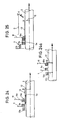
- FIG. 24 shows a structure which is equipped with a sliding sleeve 13 which is connected to the hub axle 5 in a rotationally fixed but axially displaceable manner and has two coupling teeth 13a for engagement in the coupling profiles 9a and 10a of the sun gears 9 and 10.
- the two sun gears 9 and 10 are rotatably but axially fixed in the planet carrier. From the starting position - for example as shown in FIG. 24 - in which the large sun gear 10 interacts with the axially right coupling toothing 13a of the sliding sleeve 13, the sliding sleeve is switched axially to the right via the thrust block 12. The axially left coupling toothing 13a of the sliding sleeve comes into contact with the small sun gear 9, while the clutch engagement between the large sun gear 10 and the sliding sleeve 13 is released.
- the clutch teeth 5a of the hub axle 5, the clutch teeth 13a of the sliding sleeve 13 or the inner profiles 9a, 10a of the sun gears 9 and 10 may be equipped with inclined surfaces for the positive control of the clutch engagement.
- precautions, as described in connection with FIG. 9 with regard to the sliding sleeve 13, in combination with the arrangements according to FIGS. 22, 23 and 24 can prevent idling between the gears.
Landscapes
- Engineering & Computer Science (AREA)
- Chemical & Material Sciences (AREA)
- Combustion & Propulsion (AREA)
- Transportation (AREA)
- Mechanical Engineering (AREA)
- Structure Of Transmissions (AREA)
- Retarders (AREA)
- Transmission Devices (AREA)
Abstract
Bei einer 5-Gang-Getriebenabe weist ein Planetengetriebesatz zwei Sonnenräder (9,10) auf. Auf einem Planetenradträger (6) ist mindestens ein Planetenrad (8) mit einem großen Stufenplanetenrad (8a) und einem kleinen Stufenplanetenrad (8b) gelagert. Das kleine Sonnenrad (9) kämmt mit dem großen Stufenplanetenrad (8a), und das große Sonnenrad (10) kämmt mit dem kleinen Stufenplanetenrad (8b). Die beiden Sonnenräder (9 und 10) sind selektiv auf der Nabenachse gegen Drehung feststellbar. Die Feststellung erfolgt durch einen Kupplungszahn (5a), welcher wahlweise in eine Kupplungsausnehmung (9a) des kleinen Sonnenrads (9) und in eine Kupplungsausnehmung (10a) des großen Sonnenrads (10) eingreift. An die Kupplungsausnehmung (9a) schließen sich schräge Einweiseflanken (9b) an.
Description
Die Erfindung betrifft in Übereinstimmung mit dem Oberbegriff des Anspruchs 1 eine Mehrganggetriebenabe mit mehr als 3 Gängen, insbesondere mit Rücktrittbremse, für Fahrräder oder dergleichen, umfassend
eine Nabenachse, welche eine geometrische Achse besitzt,
einen Antreiber, welcher drehbar auf der Nabenachse gelagert ist, wobei dieser Antreiber dazu ausgebildet ist, um mit mindestens einem Kettenzahnkranz ausgerüstet zu werden,
eine Nabenhülse, welche drehbar auf der Nabenachse gelagert ist,
ein Planetengetriebesystem innerhalb der Nabenhülse wobei dieses Planetengetriebesystem aufweist:
einen axial feststehenden Planetenradträger welcher auf der Nabenachse drehbar gelagert ist,
mindestens ein axial feststehendes Planetenrad, welches drehbar auf dem Planetenradträger gelagert ist, wobei dieses Planetenrad mit einem großen Stufenplanetenrad und einem kleinen Stufenplanetenrad ausgeführt ist,
Sonnenräder, nämlich ein kleines Sonnenrad zum kämmenden Eingriff mit dem großen Stufenplanetenrad (8a) und ein großes Sonnenrad zum kämmenden Eingriff mit dem kleinen Stufenplanetenrad, wobei diese Sonnenräder selektiv gegen Drehung um die Nabenachse sperrbar sind,
ein Hohlrad, welches drehbar um die Nabenachse gelagert ist,
wobei das Hohlrad in kämmendem Eingriff mit einem der Stufenplanetenräder steht,
und ferner umfassend
ein axial verschiebbares Kupplungselement, insbesondere in Form einer Kupplungsbuchse, welches in ständigem drehmomentübertragendem Eingriff mit dem Antreiber steht und selektiv zum Eingriff zu bringen ist mit entweder dem Planetenradträger oder dem Hohlrad, um gemeinsam mit dem jeweiligen Teil um die Nabenachse zu rotieren,
ein erstes Freilaufgesperre (Antriebssperrklinke - Innengesperre zwischen dem Hohlrad und der Nabenhülse,
ein zweites Freilaufgesperre (Antriebssperrklinke - Innengesperre zwischen dem Planetenradträger und der Nabenhülse und
Gangsteuerungsmittel (Zugstange - Zugkette - Anschlußteil, welche durch eine Bohrung der Nabenachse in das Nabeninnere hereingeführt sind und welche dazu bestimmt und geeignet sind, um durch einen Schlitz der Nabenachse hindurch selektiv das eine oder andere der Sonnenräder gegen die Drehung um die Nabenachse zu sperren, um selektiv das Kupplungselement mit dem Planetenradträger und dem Hohlrad zu kuppeln und um das erste Freilaufgesperre zu inaktivieren.In accordance with the preamble of claim 1, the invention relates to a multi-speed gear hub with more than 3 gears, in particular with a coaster brake, for bicycles or the like
a hub axis, which has a geometric axis,
a driver which is rotatably mounted on the hub axle, this driver being designed to be equipped with at least one sprocket,
a hub sleeve which is rotatably mounted on the hub axle,
a planetary gear system within the hub shell this planetary gear system having:
an axially fixed planet carrier which is rotatably mounted on the hub axle,
at least one axially fixed planet gear which is rotatably supported on the planet gear carrier, this planet gear being designed with a large step planet gear and a small step planet gear,
Sun gears, namely a small sun gear for meshing engagement with the large stepped planet gear (8a) and a large sun gear for meshing engagement with the small stepped planet gear, these sun gears being selectively lockable against rotation about the hub axis,
a ring gear which is rotatably mounted about the hub axis,
the ring gear in meshing engagement with one of the stepped planet gears is
and further comprehensive
an axially displaceable coupling element, in particular in the form of a coupling bush, which is in constant torque-transmitting engagement with the driver and can be brought into selective engagement with either the planet gear carrier or the ring gear in order to rotate together with the respective part about the hub axis,
a first freewheel lock (drive pawl - internal lock between the ring gear and the hub sleeve,
a second freewheel lock (drive pawl - internal lock between the planet carrier and the hub shell and
Gear control means (pull rod - pull chain - connecting part, which are introduced through a bore in the hub axle into the interior of the hub and which are intended and suitable for selectively blocking one or the other of the sun gears against rotation about the hub axle through a slot in the hub axle, to selectively couple the clutch element with the planet carrier and the ring gear and to inactivate the first freewheel lock.
Eine solche 5-Ganggetriebenabe ist aus der FR-A 914 176 bekannt.Such a 5-speed gear hub is known from FR-A 914 176.
Bei dieser bekannten Ausführungsform sind nach einer ersten Variante gem. Fig. 4 zwei Gangsteuerungsmittel von den beiden einander gegenüberliegenden Enden der Nabenachse her eingeführt. Bei dieser ersten Variante sind auf der Nabenachse für jedes der Sonnenräder Feststellverzahnungen angebracht. Die beiden Sonnenräder sind durch eine an dem kleinen Sonnenrad angreifende erste Federung so vorgespannt, daß das große Sonnenrad in Eingriff mit der zugehörigen Feststellverzahnung steht und das kleine Sonnenrad außer Eingriff mit der zugehörigen Feststellverzahnung ist. Das eine Gangsteuerungsmittel greift an dem kleinen Sonnenrad entgegen der Wirkung der ersten Federung an, um das kleine Sonnenrad in Eingriff mit der zugehörigen Feststellverzahnung zu bringen. Wenn dies geschieht, folgt das große Sonnenrad unter der Wirkung einer zweiten Federung dem kleinen Sonnenrad und kommt außer Eingriff mit der zugehörigen Feststellverzahnung. Andererseits dient das zweite Gangsteuerungsmittel, welches von dem anderen Ende der Nabenachse her eingeführt ist, dazu, um selektiv das Kupplungselement mit dem Planetenradträger oder dem Hohlrad zu verbinden.In this known embodiment according to a first variant. Fig. 4 introduced two gear control means from the two opposite ends of the hub axle. In this first variant, locking teeth are attached to the hub axle for each of the sun gears. The two sun gears are biased by a first spring engaging the small sun gear so that the large sun gear is in engagement with the associated locking gear and the small sun gear is out of engagement with the associated locking gear. One gear control means engages the small sun gear against the action of the first suspension to bring the small sun gear into engagement with the associated locking teeth. When this happens, the large sun gear follows the small sun gear under the action of a second suspension and disengages from the associated locking gear. On the other hand, the second gear control means, which is inserted from the other end of the hub axle, serves to selectively connect the clutch element to the planet carrier or the ring gear.
Nach einer zweiten Variante ist vorgesehen, von einem Ende der Nabenachse her zwei Gangsteuerungsmittel entweder konzentrisch ineinander oder nebeneinander einzuführen, wobei wiederum das eine Gangsteuerungsmittel zur selektiven Drehfestmachung jeweils eines Sonnenrads dient und das andere Gangsteuerungsmittel zur selektiven Verbindung des Kupplungselements mit dem Planetenradträger oder dem Hohlrad bestimmt ist.According to a second variant, two gear control means are either introduced concentrically into one another or next to one another from one end of the hub axis, with the one gear control means in turn selectively fixing a sun gear in each case and the other gear control means for selectively connecting the coupling element to the planet gear carrier or the ring gear is.
Eine Rücktrittbremse ist nach der FR-A 914 176 nicht vorgesehen. Weiterhin fehlt bei den Ausführungsformen nach der FR-A 914 176 eine Sicherung dafür, daß beispielsweise auch bei ungenau justierten Gangsteuerungsmitteln gleichwohl eine sichere Drehmomentübertragung gewährleistet ist.A coaster brake is not provided according to FR-A 914 176. Furthermore, in the embodiments according to FR-A 914 176 there is no safeguard that, for example, a safe torque transmission is nevertheless guaranteed even with inaccurately adjusted gear control means.
Aus der US-PS 14 90 644 ist eine 5-Ganggetriebenabe ohne Rücktrittbremse bekannt. Bei dieser bekannten Ausführungsform ist ein Planetengetriebe mit zwei Sonnenrädern, nämlich einem kleinen Sonnenrad und einem großen Sonnenrad vorgesehen.From US-
Ein Planetenradträger ist zweiteilig ausgeführt mit zwei Planetenradträgerteilen. Der eine Planetenradträgerteil trägt ein großes Planetenrad, welches in Eingriff mit dem kleinen Sonnenrad steht. Der andere Planetenradträgerteil trägt ein kleines Planetenrad, welches in Eingriff mit dem großen Sonnenrad steht.A planet gear carrier is made in two parts with two planet gear carrier parts. One planet carrier part carries a large planet gear, which is in engagement with the small sun gear. The other planet carrier part carries a small planet gear, which is in engagement with the large sun gear.
Den beiden Planetenrädern ist ein Hohlrad gemeinsam. Zwischen dem Hohlrad und der Nabenhülse läßt sich ein erstes Freilaufgesperre bilden. Zwischen dem einen Planetenradträgerteil und der Nabenhülse läßt sich ein zweites Freilaufgesperre bilden. Der gesamte Bausatz, bestehend aus den beiden Sonnenrädern, den beiden Planetenradträgerteilen, den beiden Planetenrädern und dem Hohlrad, läßt sich in fünf Bewegungsstufen längs der Nabenachse verschieben.A ring gear is common to the two planet gears. A first freewheel lock can be formed between the ring gear and the hub sleeve. A second freewheel lock can be formed between the one planet gear carrier part and the hub sleeve. The entire kit, consisting of the two sun gears, the two planet carrier parts, the two planet gears and the ring gear, can be moved in five movement stages along the hub axis.
In einem fünften Schaltzustand, entsprechend dem großen Schnellgang (Fig. 14), ist das große Sonnenrad drehfest gegenüber der Nabenachse. Der Antreiber steht in drehmomentübertragender Verbindung mit dem anderen Planetenradträgerteil. Das Hohlrad wird durch das kleine Planetenrad angetrieben und die Drehbewegung des Hohlrads wird über das erste Freilaufgesperre auf die Nabenhülse übertragen. In einem vierten Schaltzustand, entsprechend dem zweiten oder kleineren Schnellgang (Fig. 9), treibt der Antreiber wiederum den anderen Planetenradträgerteil. Das große Sonnenrad ist frei drehbar. Das kleine Sonnenrad ist durch eine Sperrklinke an der Drehung gehindert. Das Hohlrad treibt wie im fünften Schaltzustand die Nabenhülse über das erste Freilaufgesperre.In a fifth switching state, corresponding to the large overdrive (Fig. 14), the large sun gear is non-rotatable with respect to the hub axle. The driver is in a torque-transmitting connection with the other planet carrier part. The ring gear is driven by the small planet gear and the rotation of the ring gear is transmitted to the hub shell via the first freewheel lock. In a fourth switching state, corresponding to the second or lower overdrive (FIG. 9), the driver in turn drives the other planet carrier part. The large sun gear is freely rotatable. The small sun gear is prevented from rotating by a pawl. As in the fifth gear state, the ring gear drives the hub sleeve over the first freewheel lock.
In einem dritten Schaltzustand, entsprechend dem direkten Gang (Fig. 1), sind beide Sonnenräder frei drehbar. Das Hohlrad wird durch den Antreiber angetrieben und überträgt seine Drehbewegung auf die Nabenhülse über das erste Freilaufgesperre. In einem zweiten Schaltzustand, entsprechend dem kleinen Berggang (Fig. 6), wird das Hohlrad durch den antreiber angetrieben. Das kleine Sonnenrad stützt sich gegen Drehung an die Nabenachse ab, das große Sonnenrad ist frei drehbar. Der abtrieb erfolgt von dem einen Planetenradträgerteil über das zweite Freilaufgesperre.In a third switching state, corresponding to the direct gear (Fig. 1), both sun gears are freely rotatable. The ring gear is driven by the driver and transmits its rotary motion to the hub shell via the first freewheel mechanism. In a second switching state, corresponding to the small mountain gear (Fig. 6), the ring gear is driven by the driver. The small sun gear is supported against rotation on the hub axle, the large sun gear is freely rotatable. The output takes place from the one planet carrier part via the second freewheel lock.
In einem ersten Schaltzustand, entsprechend dem großen Berggang (Fig 3), ist der Antreiber in antriebsübertragender Verbindung mit dem Hohlrad. Das große Sonnenrad ist gegen Drehung gesperrt. Der Abtrieb erfolgt von dem einen Planetenradträgerteil über das zweite Freilaufgesperre zur Nabenhülse.In a first switching state, corresponding to the large uphill gear (FIG. 3), the driver is in drive-transmitting connection with the ring gear. The large sun gear is locked against rotation. The output takes place from the one planet carrier part via the second freewheel lock to the hub shell.
Der Erfindung liegt die Aufgabe zugrunde, insbesondere bei Vorhandensein einer Rücktrittbremse sicherzustellen, daß der jeweils einzustellende Drehmomentübertragungsweg zuverlässig existiert, beispielsweise auch dann, wenn die Gangsteuerungsmittel nicht vorschriftsmäßig justiert sind.The invention has for its object to ensure, in particular in the presence of a coaster brake, that the torque transmission path to be set in each case exists reliably, for example even if the gear control means are not correctly adjusted.
Zur Lösung dieser Aufgabe wird in Übereinstimmung mit dem Kennzeichen des Anspruchs 1 vorgeschlagen, daß jedes der Sonnenräder gegen Drehung um die Nabenachse durch mindestens eine Kupplungszahn-Kupplungsausnehmungskombination sperbar ist mit einem auf der Nabenachse drefhest angeordneten Kupplungszahn und einer an dem jeweiligen Sonnenrad angeordneten Kupplungsausnehmung oder umgekehrt, daß die Sperrung und die Drehungsfreigabe des jeweiligen Sonnenrads durch axiale Relativbewegung des jeweiligen Kupplungszahnes und der jeweiligen Kupplungsausnehmung erfolgt, indem der jeweilige Kupplungszahn in die jeweilige Kupplungsausnehmung eintritt bzw. aus dieser austritt, daß sowohl der Kupplungszahn als auch die Kupplungsausnehmung der Kupplungszahn-Kupplungsausnehmungskombinationen eines jeden Sonnenrads jeweils ein Paar im wesentlichen achsparalleler Kupplungsflanken umfaßt, daß einer von den Teilen: Kupplungszahn, Kupplungsausnehmung einer Kupplungszahn-Kupplungsausnehmunggskombination eines Sonnenrads (9) mindestens eine Einweiseflanke axial angrenzend an eine zugehörige Kupplungsflanke umfaßt derart, daß durch Relativdrehung des Kupplungszahns und der Kupplungsausnehmung der Kupplungszahn-Kupplungsausnehmungskombination des einen Sonnenrads bei peripherem Gehenüberstehen der Einweiseflanken des einen der Teile: Kupplungszahn und Kupplungsausnehmung gegenüber dem jeweils anderen dieser Teile eine axiale Relativverschiebung von Kupplungszahn und Kupplungsausnehmung der Kupplungszahn-Kupplungsausnehmungskombination des einen Sonnenrads in Richtung auf Eingriffslösung dieses Kupplungszahns und dieser Kupplungsausnehmung stattfindet und daß diese axiale Relativverschiebung eine axiale Folgerelativverschiebung des Kupplungszahns und der Kupplungsausnehmung der Kupplungszahn-Kupplungsausnehmungskombination des anderen Sonnenrads in Richtung auf Eingriffsherstellung der Kupplungsflanken des Kupplungszahns und der Kupplungsausnehmung der Kupplungszahn-Kupplungsausnehmungskombination des anderen Sonnenrads veranlaßt.To solve this problem it is proposed in accordance with the characterizing part of claim 1 that each of the sun gears can be blocked against rotation about the hub axis by at least one clutch tooth / clutch recess combination a coupling tooth arranged on the hub axle and a coupling recess arranged on the respective sun gear, or vice versa, that the locking and the release of rotation of the respective sun gear takes place through relative axial movement of the respective coupling tooth and the respective coupling recess by the respective coupling tooth entering the respective coupling recess or from this emerges that both the coupling tooth and the coupling recess of the coupling tooth-coupling recess combinations of each sun gear each comprise a pair of substantially axially parallel coupling flanks, that one of the parts: coupling tooth, coupling recess of a coupling tooth-coupling recess combination of a sun gear (9) has at least one axial input flank adjacent to an associated clutch flank comprises such that by relative rotation of the clutch tooth and the clutch recess of the clutch tooth-clutch recess combination n of the one sun gear in the case of peripheral walking, the projecting flanks of one of the parts protrude: clutch tooth and clutch recess relative to the other of these parts, an axial relative displacement of the clutch tooth and clutch recess of the clutch tooth-clutch recess combination of the one sun gear in the direction of disengagement of this clutch tooth and this clutch recess takes place and that this axial relative displacement an axial consequential relative displacement of the clutch tooth and the clutch recess of the clutch tooth-clutch recess combination of the other sun gear in the direction of engaging the clutch flanks of the clutch tooth and the clutch recess of the clutch tooth-clutch recess combination of the other sun gear.
Dieses Sicherungsprinzip kann auf verschiedene Weise weitergebildet werden. So ist es entsprechend dem kennzeichnenden Teil des Anspruchs 2 möglich,
daß einer von den Teilen: Kupplungszahn, Kupplungsausnehmung einer Kupplungszahn-Kunrlungsausnehmungskombination eines Sonnenrads eine Einweiseflanke axial angrenzend an das jeweils zugehörige Paar von Kupplungsflanken umfaßt, und daß die einzelnen Einweiseflanken des genannten Paars von Einweiseflanken gegenüber einer zur Achse parallelen und durch den peripheren Mittelpunkt des jeweils zugehöringen Teils: Kupplungszahn, Kupplungsausnehmung gelegten Bezugslinie in entgegengesetzter Richtung geneigt sind.This security principle can be developed in various ways. So it is possible according to the characterizing part of
that one of the parts: clutch tooth, clutch recess of a clutch tooth-Kunrlungsausnehmungskombination a sun gear comprises a flank axially adjacent to the associated pair of coupling flanks, and that the individual flanks of said pair of flanks opposite to a parallel to the axis and through the peripheral center of each associated part: clutch tooth, clutch recess reference line are inclined in the opposite direction.
Dabei kann entsprechend dem kennzeichnenden Teil des Anspruchs 3 vorgesehen sein,
daß der axialen Relativverschiebung des Kupplungszahns und der Kupplungsausnehmung der besagten Kupplungszahn-Kupplungsausnehmungskombination des einen Sonnenrads eine erste Federung (Feder) entgegenwirkt, und daß die axiale Folgerelativverschiebung des Kupplungszahns und der Kupplungsausnehmung der Kupplungszahn-Kupplungsausnehmungskombination des anderen Sonnenrads durch eine zweite Federung (Feder) bewirkt wird.It can be provided according to the characterizing part of
that the axial relative displacement of the coupling tooth and the coupling recess of the said coupling tooth-coupling recess combination of the one sun gear counteracts a first suspension (spring), and that the axial consequential relative displacement of the coupling tooth and the coupling recess of the coupling tooth-coupling recess combination of the other sun gear brings about a second suspension (spring) becomes.
Weiter kann entsprechend dem kennzeichnenden Teil des Anspruchs 4 vorgesehen sein,
daß die Kupplungszahn-Kupplungsausnehmungskombination eines ersten der Sonnenräder und die Kupplungszahn-Kupplungsausnehmungskombination eines zweiten der Sonneräder einen gemeinsamen Kupplungszahn für jede der beiden Kombinationen und je eine Ausnehmung in jedem der beiden Sonnenräder umfaßt.Furthermore, according to the characterizing part of claim 4,
that the clutch tooth-clutch recess combination of a first of the sun gears and the clutch tooth clutch recess combination of a second of the sun gears comprises a common clutch tooth for each of the two combinations and a recess in each of the two sun gears.
Es ist auch entsprechend dem kennzeichnenden Teil des Anspruchs 5 denkbar, daß die Kupplungszahn-Kupplungsausnehmungskombination eines ersten Sonnenrads einen ersten Kupplungszahn und eine erste Kupplungsausnehmung für das erste Sonnenrad umfaßt und daß die Kupplungszahn-Kupplungsausnehmungskombination des zweiten Sonnerads einen zweiten Kupplungszahn und eine zweite Kupplungsausnehmung für das zweite Sonnenrad umfaßt.It is also conceivable according to the characterizing part of
Hierbei ist es entsprechend dem kennzeichnenden Teil des Anspruchs 6 möglich,
daß der gemeinsame Kupplungszahn axial fest bezüglich der Nabenachse angeordnet ist, und daß die Sonnenräder axial beweglich gegenüber der Nabenachse sind, oder
daß entsprechend dem kennzeichnenden Teil des Anspruchs 7 der gemeinsame Kupplungszahn axial beweglich gegenüber der Nabenachse, und daß die Sonnenräder axial fest gegenüber der Nabenachse sind.Here it is possible according to the characterizing part of
that the common clutch tooth is axially fixed with respect to the hub axis, and that the sun gears are axially movable with respect to the hub axis, or
that according to the characterizing part of claim 7, the common coupling tooth axially movable with respect to the hub axis, and that the sun gears are axially fixed with respect to the hub axis.
Entsprechend den Ansprüchen 8 und 9 können die Einweiseflanken Teile der jeweiligen Kupplungsausnehmung oder Teile des jeweiligen Kupplungszahns sein.According to
Es ist entsprechend dem kennzeichnenden Teil des Anspruchs 10 möglich,
daß der Kupplungszahn mindestens einer der Kupplungszahn-Kupplungsausnehmungskombinationen einstückig mit der Nabenachse hergestellt ist.According to the characterizing part of
that the coupling tooth at least one of the coupling tooth-coupling recess combinations is made in one piece with the hub axle.
Es ist aber auch entsprechend dem kennzeichnenden Teil des Anspruchs 11 möglich,
daß der Kupplungszahn mindestens einer der Kupplungszahn-Kupplungsausnehmungskombinationen ein Teil mindestens eines Schubklotzes ist.But it is also possible according to the characterizing part of
that the coupling tooth of at least one of the coupling tooth / coupling recess combinations is part of at least one thrust block.
Bei axial beweglicher Anordnung eines gemeinsamen Kupplungszahns ist es entsprechend dem Anspruch 12 möglich,
daß der Kupplungszahn mindestens einer der Kupplungszahn-Kupplungsausnehmungskombinationen auf einer Schiebehülse angeordnet ist, welche axial beweglich ist und unverdrehbar auf der Nabenachse angebracht ist.With an axially movable arrangement of a common clutch tooth, it is possible according to
that the coupling tooth of at least one of the coupling tooth-coupling recess combinations is arranged on a sliding sleeve which is axially movable and is non-rotatably mounted on the hub axle.
Wenn für ein erstes Sonnenrad ein erster Kupplungszahn und eine erste Kupplungsausnehmung und für ein zweites Sonnenrad ein zweiter Kupplungszahn und eine zweite Kupplungsausnehmung vorhanden sind, so ist es entsprechend dem kennzeichnenden Teil des Anspruchs 13 möglich, daß eine Trennfederung (Druckfeder) swischen den beiden Sonnenrädern vorgesehen ist, daß die beiden Sonnenräder gegenüber der Nabenachse axial beweglich sind, und daß die Kupplungszähne der Kupplungszahn-Kupplungsausnehmungskombination gegenüber der Nabenachse axial fest sind.If for a first sun gear a first clutch tooth and a first clutch recess and for a second sun gear a second clutch tooth and a second clutch recess are present, it is possible according to the characterizing part of
Die Erfindung ist unabhängig davon anwendbar, ob die Gangsteurung von einem Ende oder von beiden Enden der Nabenachse her erfolgt und insbesondere auch in dem Fall, daß entsprechend dem kennzeichnenden Teil des Anspruchs 14 die Gangsteurerungsmittel zwei Gangsteuerungselemente umfassen, welche von beiden Enden der Nabenachse her in entsprechende Bohrungen der Nabenachse eingeführt sind, daß ein erstes dieser Gangsteuerungselemente dazu bestimmt und geeignet ist, um die Kupplungsbuchse wahlweise mit dem Planetenradträger und dem Hohlrad zu kuppeln und das erste Freilaufgesperre zu inaktivieren, und daß das zweite Gangsteuerungselement dazubestimmt und geeignet ist, um nach Wahl das eine oder das andere der Sonnenräder gegen Drehung um die Nabenachse zu sperren.The invention is applicable regardless of whether the gear control takes place from one end or from both ends of the hub axle and in particular also in the event that, according to the characterizing part of
Eine besonders platzsparende und formschöne Mehrganggetriebenabe erhält man entsprechend dem kennzeichnenden Teil des Anspruchs 15 dadurch, daß die Nabenhülse einen ersten Axialabschnitt von größerem Durchmesser und einen zweiten Axialabschnitt von kleinerem Durchmesser besitzt, daß der erste Axialabschnitt das Planetengetriebesystem aufnimmt und daß der zweite Axialabschnitt die Rücktrittbremse aufnimmt.A particularly space-saving and shapely multi-speed gear hub is obtained according to the characterizing part of
Wenn eine Rücktrittbremse vorgesehen ist, so ist es entsprechend dem kennzeichnenden Teil des Anspruchs 16 möglich,
daß die Rücktrittbremse einen Bremskonus und einen spreizbaren Bremsmantel umfaßt, daß der spreizbare Bremsmantel drehfest an der Nabenachse festgelegt ist, daß der Bremskonus auf dem Planetenradträger durch eine Gewindeanordnung angebracht und gegen Drehung durch eine Friktionsfeder gesichert ist, wobei eine Rüchwärtsverdrehung des Planetenradträgers unter Vermittlung der Gewindeanordnung eine Axialbewegung des Bremskonus bewirkt und wobei diese Axialbewegung des Bremskonus eine Spreizung des Bremsmantels zum bremsenden Eingriff mit der Nabenhülse bewirkt.If a coaster brake is provided, it is possible according to the characterizing part of
that the coaster brake comprises a brake cone and an expandable brake jacket, that the expandable brake jacket is fixed in a rotationally fixed manner to the hub axle, that the brake cone is attached to the planet gear carrier by a thread arrangement and is secured against rotation by a friction spring, with a backward rotation of the planet carrier by means of the thread arrangement causes an axial movement of the brake cone and wherein this axial movement of the brake cone causes the brake jacket to expand for braking engagement with the hub sleeve.
Die Erfindung läßt sich entsprechend Anspruch 17, insbesondere bei einer 5-Ganggetriebenabe und hier wieder insbesondere bei einer solchen mit Rücktrittbremse anwenden, umfassend
eine Nabenachse, welche eine geometrische Achse besitzt,
einen Antreiber, welcher auf der Nabenachse drehbar gelagert ist, wobei dieser Antreiber dazu ausgebildet ist, um mit mindestens einem Kettenzahnkranz ausgerüstet zu werden,
eine Nabenhülse, welche auf der Nabenachse drehbar gelagert ist,
ein Planetengetriebesystem innerhalb der Nabenhülse, wobei dieses Planetengetriebesystem aufweist:
einen axial feststehenden Planetenradträger, welcher auf der Nabenachse drehbar gelagert ist,
mindestens ein axial feststehendes Planetenrad, welches drehbar auf dem Planetenradträger gelagert ist, wobei dieses Planetenrad mit einem großen Stufenplanetenrad und einem kleinen Stufenplanetenrad ausgeführt ist,
Sonnenräder, nämlich ein kleines Sonnenrad zum kämmenden Eingriff mit dem großen Stufenplanetenrad und ein großes Sonnenrad zum kämmenden Eingriff mit dem kleinen Stufenplanetenrad, wobei diese Sonnenräder durch axiale Verschiebung selektiv gegen Drehung um die Nabenachse sperrbar sind,
ein Hohlrad, welches drehbar um die Nabenachse gelagert ist,
wobei das Hohlrad im kämmendem Eingriff mit einem der Stufenplanetenräder steht,
und ferner umfassend
ein axial verschiebbares Kupplungselement, insbesondere in Form einer Kupplungsbuchse, welches in ständigem drehmomentübertragendem Eingriff mit dem Antreiber steht und durch axiale Verschiebung selektiv zum Eingriff zu bringen ist mit entweder dem Planetenradträger oder dem Hohlrad, um gemeinsam mit dem jeweiligen Teil um die Nabenachse zu rotieren,
ein erstes Freilaugesperre (Antriebssperrklinke) zwischen dem Hohlrad und der Nabenhülse
ein zweites Freilaufgesperre (Antriebssperrklinke) zwischen dem Planetenradträger und der Nabenhülse,
Gangsteuerungsmittel, welche innerhalb der Nabenachse in das Nabeninnere hereingeführt sind und welche dazu bestimmt und geeignet sind, um durch eine Schlitzung der Nabenachse hindurch selektiv das eine oder andere der Sonnenräder gegen Drehung um die Nabenachse zu sperren, um das, insbesondere als Kupplungsbuchse ausgebildete, Kupplungselement zu verschieben und selektiv mit dem Planetenradträger und dem Hohlrad zu kuppeln und um das erste Freilaufgesperre zu inaktivieren,
wobei in einem 5. Schaltzustand das kleine Sonnenrad frei zur Drehung um die Nabenachse ist, das große Sonnenrad gegen Drehung um die Nabenachse gesperrt ist, das Kupplungselement in drehmomentübertragendem Eingriff mit dem Planetenradträger steht und das erste Freilaufgesperre aktiv ist,
wobei in einem 4. Schaltzustand das kleine Sonnenrad gegen Drehung um die Nabenachse gesperrt ist, das große Sonnenrad frei um die Nabenachse drehbar ist, das Kupplungselement noch in drehmomentübertragendem Eingriff mit dem Planetenradträger steht und das erste Freilaufgesperre noch aktiv ist,
wobei in einem 3. Schaltzustand das kleine Sonnenrad gegen Drehung um die Nabenachse gesperrt ist, das große Sonnenrad um die Nabenachse frei drehbar ist, das Kupplungselement in drehmomentübertragendem Eingriff mit dem Hohlrad ist und das erste Freilaufgesperre noch aktiv ist,
wobei in einem 2. Schaltzustand das kleine Sonnenrad gegen Drehung um die Nabenachse gesperrt ist, das große Sonnenrad frei um die Nabenachse drehbar ist, das Kupplungselement in drehmomentübertragender Verbindung mit dem Hohlrad steht und das erste Freilaufgesperre inaktiviert ist,
wobei in einem 1. Schaltzustand das kleine Sonnenrad frei drehbar um die Nabenachse ist, das große Sonnenrad gegen Drehung um die Nabenachse gesperrt ist, das Kupplungselement in drehmomentübertragendem Eingriff mit dem Hohlrad steht und das erste Freilaufgesperre inaktiviert ist, und
wobei die Gangsteuerungsmittel je ein von den beiden Enden der Nabenachse her eingeführtes Gansteuerungsorgan aufweisen, deren eines zum selektiven Verbinden des Kupplungselement mit dem Planetenradträger und dem Hohlrad bestimmt ist, deren anderes zum selektiven Drehfestmachen des kleinen Sonnenrads und des großen Sonnenrads bestimmt ist.The invention can be applied in accordance with
a hub axis, which has a geometric axis,
a driver which is rotatably mounted on the hub axle, this driver being designed to be equipped with at least one sprocket,
a hub sleeve which is rotatably mounted on the hub axle,
a planetary gear system within the hub sleeve, this planetary gear system having:
an axially fixed planet carrier, which is rotatably mounted on the hub axle,
at least one axially fixed planet gear which is rotatably supported on the planet gear carrier, this planet gear being designed with a large step planet gear and a small step planet gear,
Sun gears, namely a small sun gear for meshing engagement with the large stepped planet gear and a large sun gear for meshing engagement with the small stepped planet gear, these sun gears being selectively lockable against rotation about the hub axis by axial displacement,
a ring gear which is rotatably mounted about the hub axis,
the ring gear in meshing engagement with a the stepped planet gears stand,
and further comprehensive
an axially displaceable coupling element, in particular in the form of a coupling bush, which is in constant torque-transmitting engagement with the driver and can be brought into engagement selectively by means of axial displacement with either the planet gear carrier or the ring gear in order to rotate together with the respective part about the hub axis,
a first outdoor lock (drive pawl) between the ring gear and the hub shell
a second freewheel lock (drive pawl) between the planet carrier and the hub shell,
Gear control means which are introduced into the hub interior within the hub axle and which are intended and suitable for selectively blocking one or the other of the sun gears against rotation about the hub axle through a slot in the hub axle in order to engage the clutch element, in particular in the form of a clutch bushing move and selectively couple with the planet carrier and the ring gear and to deactivate the first freewheel lock,
in a 5th switching state, the small sun gear is free to rotate about the hub axis, the large sun gear is locked against rotation about the hub axis, the coupling element is in torque-transmitting engagement with the planet gear carrier and the first freewheel lock is active,
the small sun gear in a 4th switching state is locked against rotation around the hub axis, the large sun gear is freely rotatable about the hub axis, the coupling element is still in torque-transmitting engagement with the planet gear carrier and the first freewheel lock is still active,
in a third switching state the small sun gear is locked against rotation about the hub axis, the large sun gear is freely rotatable about the hub axis, the coupling element is in torque-transmitting engagement with the ring gear and the first freewheel lock is still active,
in a second switching state, the small sun gear is locked against rotation about the hub axis, the large sun gear is freely rotatable about the hub axis, the coupling element is in torque-transmitting connection with the ring gear and the first freewheel lock is deactivated,
wherein in a 1st switching state, the small sun gear is freely rotatable about the hub axis, the large sun gear is locked against rotation about the hub axis, the coupling element is in torque-transmitting engagement with the ring gear and the first freewheel lock is deactivated, and
the gear control means each having a gan control member inserted from the two ends of the hub axle, one of which is intended for selectively connecting the coupling element to the planet gear carrier and the ring gear, the other of which is intended for selectively tightening the small sun gear and the large sun gear.
Dabei läßt sich entsprechend dem kennzeichnenden Teil des Anspruchs 17 ein sehr kompakter und einfacher Aufbau dadurch erzielen,
daß für die selektive Drehfestmachung der beiden Sonnenräder ein einziges nabenachsenfestes Kupplungselement vorgesehen ist, welches bei axialer Verschiebung der Sonnenräder wahlweise in Eingriff mit dem kleinem und dem großen Sonnenrad tritt.It can be achieved in accordance with the characterizing part of
that for the selective rotation of the two sun gears a single hub-axis-fixed coupling element is provided, which optionally comes into engagement with the small and the large sun gear when the sun gears are axially displaced.
Es ist entsprechend dem kennzeichnenden Teil des Anspruchs 18 denkbar,
daß die beiden Sonnenräder durch eine Feder gegen einen mit einem zugehörigen Gangsteuerungsorgan verbundenen Schubklotz in eine Stellung vorgespannt sind, in welcher eines der Sonnenräder in Eingriff mit dem nabenachsenfesten Kupplungselement steht, und daß bei Verschieben dieses Schubklotzes die Feder das eine Sonnenrad außer Eingriff und das andere Sonnenrad in Eingriff mit dem nabenachsenfesten Kupplungselement verschiebt.According to the characterizing part of
that the two sun gears are biased by a spring against a thrust block connected to an associated gear control member in a position in which one of the sun gears is in engagement with the coupling element fixed to the hub axle, and that when this thrust block is moved, the spring disengages one sun gear and the other Sun gear in engagement with the hub axle fixed coupling element.
Entsprechend dem Anspruch 19 können dabei zwischen den beiden Sonnenrädern Anschlagmittel vorgesehen sein.According to
Bevorzugt wird entsprechend dem Anspruch 20 eine Bauweise derart gewählt,
daß das kleine Sonnenrad antreiberfern und das große Sonnenrad antreibernahe angeordnet sind, daß die beiden Sonnenräder durch die feder in Richtung auf Eingriff des kleinen Sonnenrads mit dem nabenach-senfesten Kupplungselement vorgespannt sind,
daß das den Sonnenrädern zugeordnete Gangsteuerungsorgan von dem antreiberfernen Ende der Nabenachse her in diese eingefürht ist, und daß durch Ziechen dieses Gangsteuerungsorgans die Sonnenräder gemeisam gegen die Weitung der Feder in Stellungen verschiebbar sind, in welchen das große Sonnenrad in Eingriff mit dem achsfesten Kupplungselement steht und das kleine Sonnenrad außer Eingriff mit diesem Kupplungselement steht.According to
that the small sun gear is remote from the driver and the large sun gear is arranged near the driver, that the two sun gears are biased by the spring in the direction of engagement of the small sun gear with the coupling element fixed to the hub,
that the gear control member assigned to the sun gears from the driver distal end of the hub axle is inserted into it, and that by pulling this gear control member the sun gears can be moved together against the extension of the spring into positions in which the large sun gear is in engagement with the axially fixed coupling element and the small sun gear is disengaged from this coupling element stands.
Entsprechend dem kennzeichnenden Teil des Anspruchs 21 ist es möglich,
daß das dem antreiberseitigen Kupplungselement (Kupplungsbuchse zugeordnete Gangsteuerungsorgan von dem antreiberseitigen Nabenachsenende her in die Nabenachse eingeführt ist, daß Kupplungselement (Kupplungsbuchse) durch eine Federung (Druckfeder) in Richtung auf Eingriff mit dem Planetenradträger vorgespannt ist, daß das Kupplungselement durch Ziehen des zugehörigen Gangsteuerungsorgans aus dem Eingriff mit dem Planetenradträger trennbar und zum Eingriff mit dem Hohlrad (11) bringbar ist, und daß durch weiteres Ziehen dieses Gangsteuerungsorgans das 1. Freilaufgesperre inaktivierbar ist.According to the characterizing part of
that the gear control element assigned to the driver-side coupling element (clutch bushing) is inserted into the hub axis from the driver-side hub axis end, that the coupling element (coupling bushing) is biased by a spring (compression spring) in the direction of engagement with the planet gear carrier, that the coupling element is pulled out by pulling the associated gear control element the engagement with the planet carrier is separable and can be brought into engagement with the ring gear (11), and that by pulling this gear control member the 1st freewheel lock can be deactivated.
Die beiliegenden Figuren erläutern die Erfindung an Hand von Ausführungsbeispielen.
Im einzelnen zeigt
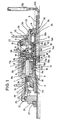
- Fig. 1 eine von einer Nabenachsseite schaltbare Mehrgangnabe mit fünf Gängen und mit einer Rücktrittbremseinrichtung, im halben Längsschnitt,
- Fig. 2a und 2a′ bzw. 2b und 2b′ jeweils eine Anordnung, bei welcher Sonnenräder axial verschiebbar auf der Nabenachse gelagert sind und diese Achse mit einer Kupplungsverzahnung ausgerüstet ist,
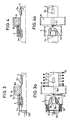
- Fig. 3, 3a bzw. 4, 4a jeweils eine Anordnung von axial verschiebbaren, auf der Nabenachse gelagerten Sonnenrädern, wobei die Nabenachse zwei Kupplungsverzahnungen aufweist,
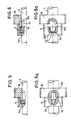
- Fig. 5, 5a bzw. 6, 6a jeweils eine Anordnung von axial festen Sonnenrädern auf der Nabenachse, wobei ein Kupplungselement in der Nabenachse axial verschiebbar ist,
- Fig. 7, 7a bzw. 8, 8a jeweils eine Anordnung von axial festgelegten Sonnenrädern auf der Nabenachse, es sind zwei verschiebbare Kupplungselemente in der Nabenachse vorgesehen,
- Fig. 9 und 9a eine Anordnung axial festgelegter Sonnenräder, wobei auf der Nabenachse eine mit Kupplungselementen versehene Schiebehülse vorgesehen ist,
- Fig. 10 bzw. 11 jeweils eine Anordnung von axial festgelegten Sonnenrädern, die mittels einer auf der Nabenachse drehfesten Schiebehülse wechselweise kuppelbar sind,
- Fig. 12 bzw. 13 Beispiele für Umschaltsysteme für die Sonnenräder, wobei Leerlaufschaltstellungen vermieden sind,
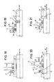
- Fig. 14 bzw. 15 jeweils eine Möglichkeit dafür, eines der mit der Nabenachse drehfest zu kuppelnden Sonnenräder axial zu verrasten,
- Fig. 16, 17 bzw. 18 Schaltsysteme, bei welchen die Sonnenräder für sich axial festgelegt sind und jeweils über eine mit der Nabenachse drehfeste, jedoch axial verschiebbare zur Kupplung der Sonnenräder dienende Schiebehülse axial verrastet werden können,
- Fig. 19 bzw. 20 Varianten zu den Ausführungsformen
gemäß den Figuren 16bis 18, bei weichen nunmehr zum Umschalten der auf der Nabenachse axial verschiebbar gelagerten Sonnenräder eine Hilfshülse verwendet ist, welche ihrerseits zur Nabenachse oder zum Planetenträger verrastbar ist, - Fig. 21 eine Anordnung, bei der bei axial verschiebbaren Sonnenrädern der Schubklotz in der Nabenachse selbst zur Vorgabe der funktionsrichtigen Schaltwege einrastet,
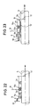
- Fig. 22 bzw. 23 jeweils ein Schaltungssystem, das bei axial verschiebbaren Sonnenrädern in nur eine Richtung geschaltet werden muß,
- Fig. 24 einen Aufbau für eine Schaltbetätigung in nur eine Richtung bei axial festgelegten Sonnenrädern,
- Fig. 24a eine Variante zum Aufbau gem. Fig.24,
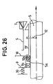
- Fig. 25 bzw. 26 ein Aufbau für ein Schaltsystem für axial verschiebbare Sonnenräder, wobei in unterschiedlicher Weise eine Bewegungsumkehr einer speziellen Steuerhülse erreicht wird,
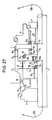
- Fig. 27 ein Ausführungsbeispiel einer 5-Gang-Nabe mit zwei Schaltbetätigungselementen,
- Fig. 28 ein Ausführungsbeispiel einer 5-Gang-Nabe mit nur einem Schaltbetätigungselement,
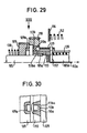
- Fig. 29 eine konstruktive Abwandlung zu Fig. 1 in schematischer Teildarstellung,
- Fig. 30 eine Ansicht zu Fig. 29 in Pfeilrichtung XXX derr Fig. 29.
In detail shows
- 1 is a switchable from a hub axle side multi-speed hub with five gears and with a coaster brake device, in half longitudinal section,
- 2a and 2a 'or 2b and 2b' each have an arrangement in which sun gears are axially displaceably mounted on the hub axle and this axle is equipped with a coupling toothing,
- 3, 3a and 4, 4a each have an arrangement of axially displaceable sun gears mounted on the hub axle, the hub axle having two clutch teeth,
- 5, 5a and 6, 6a each have an arrangement of axially fixed sun gears on the hub axle, a coupling element being axially displaceable in the hub axle,
- 7, 7a and 8, 8a each have an arrangement of axially fixed sun gears on the hub axle, two displaceable coupling elements are provided in the hub axle,
- 9 and 9a an arrangement of axially fixed sun gears, a sliding sleeve provided with coupling elements being provided on the hub axle,
- 10 and 11 each show an arrangement of axially fixed sun gears which can be alternately coupled by means of a sliding sleeve which is non-rotatable on the hub axle,
- 12 and 13 examples of switching systems for the sun gears, idle switching positions are avoided,
- 14 and 15 each have a possibility for axially locking one of the sun gears to be coupled in a rotationally fixed manner to the hub axle,
- 16, 17 and 18 shifting systems in which the sun gears are axially fixed for themselves and can each be axially locked via a sliding sleeve which is non-rotatable but axially displaceable for coupling the sun gears,
- 19 and 20 variants of the embodiments according to FIGS. 16 to 18, in the case of which an auxiliary sleeve is now used for switching over the sun gears which are axially displaceably mounted on the hub axle and which in turn can be locked to the hub axle or to the planet carrier,
- 21 shows an arrangement in which, in the case of axially displaceable sun gears, the thrust block engages in the hub axis itself for specifying the functionally correct shifting paths,
- 22 and 23, respectively, a circuit system that has to be switched in only one direction with axially displaceable sun gears,
- 24 shows a structure for shift actuation in only one direction with axially fixed sun gears,
- 24a shows a variant for the construction according to Fig. 24,
- 25 and 26 a structure for a switching system for axially displaceable sun gears, wherein a reversal of movement of a special control sleeve is achieved in different ways,
- 27 shows an exemplary embodiment of a 5-speed hub with two shift actuating elements,
- 28 shows an exemplary embodiment of a 5-speed hub with only one shift actuating element,
- 29 shows a structural modification to FIG. 1 in a schematic partial illustration,
- 30 is a view of FIG. 29 in the direction of arrow XXX of FIG. 29.
Bei der in Figur 1 beispielsweise gezeigten Mehrgangnabe mit mehr als drei Gängen und einer Rücktrittbremseinrichtung ist mit 1 die Nabenhülse bezeichnet, welche über Kugelläufe 21 und 22 auf einem Hebelkonus 26 und einem Antreiber 3 drehbar gelagert ist. Der in Mitnehmernuten 3a einen Kettenzahnkranz 3′ tragende Antreiber 3 ist seinerseits über einen Kugellauf 23 drehbar auf einem mit der Nabenachse 5 verschraubten Festkonus 4 gelagert.In the multi-speed hub shown in FIG. 1, for example, with more than three gears and a coaster brake device, the hub sleeve is designated by 1, which is rotatably mounted on a
Im Inneren der Nabenhülse 1 ist ein Planetenradträger 6 auf der Nabenachse 5 drehbar, jedoch axial festliegend, gelagert. Dieser Planetenradträger 6 weist auf Bolzen 7 gelagerte Planetenräder 8 auf, die als Stufenplanetenräder 8a und 8b ausgebildet sind, welche sowohl mit einem konzentrischen Hohlrad 11 als auch mit auf der Nabenachse 5 angeordneten Sonnenrädern 9 bzw. 10 kämmen.In the interior of the hub shell 1, a
Die Sonnenräder 9 bzw. 10 können mittels eines Schubklotzes 12, der in einem Schlitz 5b der Nabenachse 5 gegen die Spannung einer Druckfeder 28 gleitet und von einer Zugstange 12a über eine Zugkette 12b mit Anschlußteil 12c von außen betätigt werden kann, gesteuert werden. Dabei wirkt auf das axial linke Sonnenrad 9 ständig eine coaxiale Druckfeder 30, deren Spannung durch Anliegen des Sonnenrades 9 am Sonnenrad 10 auch an letzteres weitergeleitet wird. - Die Betätigungseinrichtung für die Zugstange 12a mit Kette 12b und Anschlußteil 12c zur Steuerung des Schubklotzes 12 ist hier nicht dargestellt. - Die in ihrer Zähnezahl unterschiedlichen Sonnenräder 9 bzw. 10 sind wechselweise drehfest kuppelbar, wobei das Sonnenrad 9 mit axialen Kupplungsklauen 9a durch axiales Verschieben mit entsprechenden Klauen 13a einer Schiebehülse 13 gekuppelt werden kann, welche ihrerseits auf der Nabenachse 5 drehfest mittels Achsklauen 5a angeordnet, jedoch axial verschiebbar ist. In der in Figur 1 dargestellten Gangschaltstellung der Mehrgangnabe ist das in der Zähnezahl größere Sonnenrad 10 mittels radialer Kupplungselemente 10a mit der das Sonnenrad 10 coaxial aufnehmenden Schiebehülse 13 drehfest, jedoch für sich axial verschiebbar verbunden.Das Sonnenrad 10 kämmt dabei mit einem in der Zähnezahl kleineren Stufenplanetenrad 8b, während das auf der Nabenachse 5 lose drehbar befindliche Sonnenrad 9 mit dem in der Zähnezahl größeren Planetenstufenrad 8a kämmt. Auf beide Sonnenräder 9 und 10 wirkt von axial links die Druckfeder 30.The sun gears 9 and 10 can be controlled by means of a
Auf der Nabenachse 5 ist coaxial zur Schiebehülse 13 eine Kupplungsbuchse 14 drehbar und gegen Federspannung axial verschiebbar angeordnet, wie noch zu beschreiben sein wird. An ihrem Außenumfang ist die Kupplungsbuchse 14 mit axial getrennten Verzahnungen 14a und 14b versehen, wobei die axial linksseitige Verzahnung 14a zusätzlich zur drehfesten Aufnahme einer seitlich angeordneten Mitnehmerscheibe 15 eingerichtet ist. Die axial rechte Verzahnung 14b der Kupplungsbuchse 14 ist ständig im Eingriff mit der axial lang ausgebildeten in Innenverzahnung 3b des Antreibers 3.On the
Durch axiales Verschieben der Kupplungsbuchse 14 ist entweder die Mitnehmerscheibe 15 mit axialen Klauen 6b am Planetenradträger 6 oder die Außenverzahnung 14a mit einer entsprechenden Innenverzahnung 11b am Hohlrad 11 kuppelbar, wie noch näher zu beschreiben sein wird. Axial linksseitig zur Kupplungsbuchse 14 ist auf den Klauen 6b des Planetenradträgers 6 festliegend eine Scheibe 16 angeordnet, deren Funktion später noch erwähnt werden wird.By axially displacing the
Auf dem axial äußerst linksseitigen Schaftteil des Planetenradträgers 6 ist auf einem Stellgewinde 6a axial verschiebbar ein Bremskonus 17 angeordnet, weicher zugleich als Träger für einen Satz Antriebssperrklinken 18 ausgebildet ist, weich letzterer unter Spannung einer Ringfeder stehend, ständig in ein Innengesperre 1a der Nabenhülse 1 eingreifen.On the axially extreme left-hand shaft part of the
Das vorerwähnte Hohlrad 11 trägt auf dem mit der Innenverzahnung 11b versehenen Ansatzteil einen weiteren Satz federgespannter Antriebssperrklinken 19, welche Je nach Lage des axial verschiebbar angeordneten Hohlrades 11 in ein Innengesperre 1b der Nabenhülse 1 in Eingriff treten können wie es beispielsweise in Figur 1 gezeigt wird, oder auch mittels einer Konusfläche 1c in der Nabenhülse 1 außer Eingriff gebracht werden können.The
Der vorerwähnte Bremskonus 17 wird seinerseits unter Einwirkung einer Friktionsfeder 20 stehend, in noch zu beschreibender Weise bei Rückwärtsdrehen des Antreibers 3 auf dem Stellgewinde des Planetenradträgerschaftes nach axial links bewegt und spreizt dadurch einen Bremsmantel 24/25 auf, der seinerseits an einem mit Bremshebel 27 versehenen Hebeikonus 2 drehfest gehalten wird. Durch die Aufspreizung des Bremsmantels 24 in der Nabenhülse 1 wird diese zuverlässig gebremst.The
Der vorerwähnte Schubklotz 12 steht, wie Figur 1 deutlich erkemen läßt, unter Spannung einer coaxialen Druckfeder 28, welche sich am Festkonus 4 auf der Nabenachse 5 abstützt und kann innerhalb des Schlitzes 5b in der Nabenachse 5 mittels der Zugstange 12a mit angeschlossener Zugkette 12b und Ansatzteil 12c axial nach rechts verschoben werden, zur Erzielung von anderen Gangschaltstufen, wie noch zu beschreiben sein wird. Der mit dem Ansatzteil 12c mittels Schaltzug verbundene Gangschalter ist hier nicht gezeigt.The above-mentioned
In Figur 1 ist die beispielsweise gezeigte Mehrgangnabe in der Schaltstellung 5. Gang (großer Schnellgang) dargestellt. Der durch die Feder 28 belastete Schubklotz 12 befindet sich in der axial linken Stellung Innerhalb des Nabenachsschlitzes 5b. Die Schiebehülse 13 befindet sich unter Wirkung einer coaxialen Druckfeder 34 stehend, in der axial linken Endsteilung, welche durch die zur drehfesten Halterung der Schiebehülse 13 dienenden Achsklauen 5a bestimmt wird. Die Schiebehülse 13 wird umgeben von einer Zwischenhülse 29, welche vom Schubklotz 12 ohne Spiel durchdrungen wird, wie Figur 1 deutlich erkennen läßt. Diese Zwischenhülse 29 bildet den axialen Anschlag nach rechts für das Sonnenrad 10, welches linksseitig vom unter Wirkung der Druckfeder 30 stehenden Sonnenrad 9 beaufschlagt wird. In der Gangschaltstellung gemäß Figur 1 ist das Sonnenrad 10 mittels seiner radialen Kupplungselemente 10a mit der Schiebehülse 13 über radial nach außen gerichtete Kupplungselemente 13b drehfest verbunden. Damit ist das Sonnenrad 10 mittelbar drehfest auf der Nabenachse 5, während das Sonnenrad 9 auf der Nabenachse 5 in dieser Gangschaltstellung frei drehbar ist, weil infolge der Lage axial äußerst links keine Kupplungsverbindung mit den axialen Elementen 9a des Sonnenrades 9 mit der entsprechenden Kupplungsverzahnung 13a der Schiebehülse 13 besteht.In Figure 1, the multi-speed hub shown, for example, is shown in the 5th gear position (high overdrive). The
Wie in Figur 1 erkennbar, steht die Kupplungsbuchse 14 mit ihrer Verzahnung 14b im Eingriff im Antreiber 3/3b, während die Verzahnung 14a über die auf ihr drehfest angebrachte Mitnehmerscheibe 15 mit den Klauen 6b des Planetenradträgers 6 in Wirkverbindung steht. Der Planetenradträger 6 treibt über seine Lagerbolzen 7 die Planetenräder 8 an, wovon das Stufenrad 8b mit dem in vorbeschriebener Weise drehfesten Sonnenrad 10 einerseits und andererseits mit der Hohlradverzahnung 11a kämmt. Das Hohlrad 11 steht über den Antriebsklinkensatz 19 mit dem Innengesperre Ib in der Nabenhülse 1 in Verbindung.As can be seen in FIG. 1, the
Der Drehmomentenfluß hat im gezeigten 5. Gang folgenden Verlauf:The torque flow has the following course in the 5th gear shown:
Kettenrad auf Antreiber 3 mit Innenverzahnung 3b - Außenverzahnung 14b auf Kupplungshülse 14 zur Außenverzahnung 14a mit Mitnehmerscheibe 15 - Klauen 6b am Planetenradträger 6 - Planetenradlagerbolzen 7 mit Planetenrad 8 - Stufenrad 8b auf dem drehfesten Sonnenrad 10 abrollend - Innenverzahnung 11a im Hohlrad 11 - Antriebssperrklinken 19 - Innengesperre 1b in der Nabenhülse 1. Die Antriebssperrklinken 18 auf dem mit dem Planetenradträger 6 langsamer umlaufenden Bremskonus 17 werden von dem Innengesperre 1a der Nabenhülse 1 überholt.Sprocket on
Zur Schaltstellung 4. Gang (kleiner Schnellgang) wird der Schubklotz 12 soweit nach axial rechts gezogen, daß das an der Zwischenhülse 29 unmittelbar anliegende Sonnenrad 10 unter Einfluß des unter Wirkung der Druckfeder 30 stehenden Sonnenrades 9 axial nach rechts verschoben wird bis zum Eingriff der Kupplungsklauen 9a in die Klauen 13a der Schiebehülse 13, während die Kupplungselemente 10a des Sonnenrades 10 nunmehr außer Eingriff mit der Schiebehülse 13/13b kommen. Die übrigen Elemente des Nabengetriebes bleiben in der bei der Schaltstellung 5. Gang geschilderten Lage. Der Drehmomentenfluß ist im 4. Gang nunmehr folgender:For the 4th gear shift position (low overdrive), the
Kettenzahnkranz auf Antreiber 3 mit Innenverzahnung 3b - Außenverzahnung 14b auf Kupplungsbuchse 14 zur linken Außenverzahnung 14a mit Mitnehmerscheibe 15 - Klauen 6b am Planetenradträger 6 - Lagerbolzen 7 mit Planetenrädern 8b/8a - Planetenstufenrad 8a am Sonnenrad 9 und in Hohlrad 11/11a abrollend-Antriebssperrklinken 19 am Hohlrad 11 - Nabenhülse 1 mit Innengesperre 1b.Chain sprocket on
Zur Schaltstellung Normalgang (3.Gang) wird der Schubklotz 12 noch weiter nach axial rechts gezogen, so daß die Kupplungsbuchse 14 nunmehr infolge Anliegens der Zwischenhülse 29 an der in der Kupplungsbuchse 14 konzentrischen Druckfeder 32 gegen die an der Mitnehmerscheibe 15 anliegende Druckfeder 35 nach axial rechts verschoben wird und mit der Außenverzahnung 14a in Eingriff mit der Innenverzahnung 11b des Hohlrades 11 kommt, während die zuvor wirksame Mitnehmerscheibe 15 außer Eingriff kommt. Das zuvor drehfest gekuppelte Sonnenrad 9 bleibt in seiner Lage, das Sonnenrad 10 bleibt weiterhin drehbar auf der Schiebehülse 13.To the normal gear (3rd gear) switch position, the
Der Drehmomentenfluß ist nun wie folgt:The torque flow is now as follows:
Kettenzahnkranz auf Antreiber 3 mit Innenverzahnung 3b - Außenverzahnung 14b der Kupplungsbuchse 14 mit Außenverzahnung 14aHohlrad-Innenverzahnung 11b - Hohlrad 11 mit Antriebssperrklinken 19 - Innengesperre 1b in der Nabenhülse 1. - Der Planetenradträger selbst wird langsamer angetrieben, so daß die Sperrklinken 18 auf dem Bremskonus 17 von der Nabenhülse 1 überholt werden.Chain sprocket on
Zur Schaltstellung 2. Gang (großer Berggang) wird mittels der Schalteinrichtung der Schubklotz 12 noch mehr nach axial rechts gezogen, so daß über die Kupplungsbuchse 14 das Hohlrad 11 gegen die Spannung der Druckfeder 36 soweit verschoben wird, daß die Sperrklinken 19 auf dem Hohlrad an der Schaltkonusfläche 1c der Nabenhülse 1 außer Eingriff gebracht werden.For the switching position 2nd gear (large mountain gear), the
Die Axialbewegung des Schubklotzes relativ zur Schiebehülse 13 wird durch einen axial langen Schlitz 13c ermöglicht. Die Schiebehülse 13 ist in der in Figur 1 erkennbaren axialen Lage verblieben, die im Zusammenhang mit der Schaltstellung 4. Gang erwähnte drehfeste Kupplung des Sonnenrades 9 mit der Schiebehülse 13 besteht unverändert weiterhin. Entsprechend ist das Sonnenrad 10 drehbar auf der Schiebehülse 13.The axial movement of the thrust block relative to the sliding
Der Drehmomentenfluß im 2. Gang (großer Berggang) ist folgender:The torque flow in 2nd gear (large mountain gear) is as follows:
Kettenkranz auf Antreiber 3 mit Innengesperre 3b - Außenverzahnung 14b der Kupplungsbuchse mit Außenverzahnung 14a - Innenverzahnung 11b im Ansatz des Hohlrades 11 - Innenverzahnung 11a des Hohlrades - Planetenstufenrad 8b - Stufenrad 8a am Sonnenrad 9 abrollend - Lagerbolzen 7 des axial festliegenden Planetenradträgers - Planetenradträger 6 mit Bremskonus 17 auf dem Stellgewinde 6a - Sperrklinkensatz 18 - Innengesperre 1a der Nabenhülse 1.Chain ring on
Zur Schaltstellung 1. Gang (kleiner Berggang) wird mittels der Schaltbetätigung der Schubklotz 12 noch weiter nach axial rechts gezogen, wobei nunmehr die Schiebehülse 13 infolge Anschlagens des Schubklotzes an das Ende des Längsschlitzes 13c selbst gegen die Druckfeder 34 nach axial rechts verschoben und dabei auch die Feder 32 komprimiert wird. Dadurch ist die zuvor noch bestehende Kupplungsverbindung zwischen dem Sonnenrad 9 und der Schiebehülse 13 gelöst worden, weil das Sonnenrad 9 der Verschiebebewegung der Schiebehülse 13 nicht mehr folgen kann, sondern infolge Anliegens des benachbarten Sonnenrades 10 an einer Zwischenscheibe 16 axial festgelegt wird. Diese Zwischenscheibe 16 ist auf den Klauen 6b des axial festliegenden Planetenradträgers G angebracht. - Die axial nach weiter rechts verschobene Schiebehülse 13 bildet mit ihren Kupplungskauen 13b nunmehr eine drehteste Kupplung mit dem axial rechts an der Zwischenscheibe 16 anliegenden Sonnenrad 10. Die Schiebehülse 13 selbst wird auch in dieser Lage von den Achsklauen 5a drehfest auf der Nabenachse 5 gehalten.For the switching position 1st gear (small uphill gear), the
Der Drehmomentenfluß in der Schaltstellung 1. Gang ist wie folgt:
Kettenkranz auf Antreiber 3 mit Innenverzahnung 3b - Außenverzahnung 14b der Kupplungsbuchse 14 mit Außenverzahnung 14aInnenverzahnung 11b im Hohlradansatz - Innenverzahnung 11a des Hohlrades 11 - Planetenstufenrad 8b auf Sonnenrad 10 kämmend -Planetenradlagerbolzen 7 im Planetenradträger 6 - Bremskonus 17 auf Stellgewindeansatz 6a - Sperrklinkensatz 18 in Innengesperre 1a der Nabenhülse 1 eingreifend.The torque flow in the 1st gear switch position is as follows:
Chain ring on
Wie sich aus der vorstehenden Schilderung deutlich ergibt, weist die Ausführungsform einer erfindungsgemäßen Mehrgangnabe mit mehr als drei Gängen Insbesondere eine Anordnung von konzentrischen Hülsenelementen auf, mit deren relativer Verschiebung zueinander gegen Federspannung die Gangumschaltung bewirkt wird. Es sind dies zum einen die radial äußere Kupplungsbuchse 14, zum anderen gehört zu dieser Hülsenanordnung die auf der Schiebehülse 13 verschiebbare Zwischenhülse 29, welche unmittelbar vom Schubklotz 12 gesteuert, Ihrerseits die Sonnenräder 9 und 10 axial steuern, und schließlich die radial innere Schiebehülse 13 selbst, welche unmittelbar auf der Nabenachse 5 verschiebbar ist und entsprechend der axialen Lage zur wechselweisen drehfesten Kupplung mit dem Sonnenrad 9 bzw. Sonnenrad 10 ausgebildet ist. Dabei ist zur Erzielung einer ständigen Kupplungsbereitschaft entweder an der Schiebehülse 13 oder auch an einem der Sonnenräder 9 bzw. 10, vorzugsweise am kleinen Sonnenrad 9 ein System von Abweisschrägen vorgesehen. - Die bei der Hülsenanordnung vorhandenen konzentrischen Druckfedern 28 und 34 können zweckmäßig mittels entsprechender Endkappen mit Axiallänge von Teilen voneinander distanziert werden.As can be clearly seen from the above description, the embodiment of a multi-speed hub according to the invention with more than three gears has, in particular, an arrangement of concentric sleeve elements, the relative shift of which against spring tension causes the gear shift. On the one hand, there are the radially
Die vorstehende Beschreibung eines Ausführungsbeispieles einer Mehrgangnabe mit mehr als drei Gängen zeigt deutlich, daß lediglich ein einziges Planetengetriebe mit Planetenstufenrädern auf einem axial festliegenden Planetenradträger und mit einem axial verschiebbaren Hohlrad sowie wechselweise drehfest kuppelbaren Sonnenrädern unterschiedlicher Zähnezahl angewendet wird.The above description of an embodiment of a multi-speed hub with more than three gears clearly shows that only a single planetary gear with planetary gears on an axially fixed planet carrier and with an axially displaceable ring gear and alternately non-rotatably coupled sun gears of different numbers of teeth is used.
Dabei erfolgt die Steuerung der vorbeschriebenen fünf Gangschaltstufen ausschließlich von einer Seite der Nabenachse her mittels eines einzigen Schaltelements, wovon hier lediglich der Schubklotz 12 an der Zugstange 12a mit Zugkette 12b gezeigt ist.The control of the five gear shift stages described above takes place exclusively from one side of the hub axle by means of a single shift element, of which only the
Die vorbeschriebene Schaltnabe mit mehr als drei Gängen hat außer der äußerst einfachen und zuverlässigen Steuerung von lediglich einer Nabenseite her noch den Vorteil, daß in der Nabe eine Rücktrittbremseinrichtung untergebracht werden kann. Diese Rücktrittbremseinrichtung hat beispielsweise bei einem Bremsvorgang aus dem Fahren mit dem zuletzt geschilderten 1. Gang folgende Betriebsweise:
Bei Rückwärtsdrehen des Antreibers 3 wird diese Drehbewegung über den Drehmomentenpfad des 1. Ganges geleitet. Der rückwärtsdrehende Planetenradträger 6 verschiebt mittels seines Stellgewindes 6a den von der Friktionsfeder 20 gegen Mitdrehen gehaltenen Bremskonus 17 nach axial links, wodurch der am Hebeikonus 2 drehfest gehaltene Bremsmantel 24 innerhalb der Nabenhülse 1 im Bremssinn aufgespreizt wird. - Die Antriebssperrklinken 18 bleiben bei der Rückwärtsdrehung des Systems wirkungslos.The above-described shift hub with more than three gears has, in addition to the extremely simple and reliable control from only one hub side, the advantage that a coaster brake device can be accommodated in the hub. This coaster brake device has the following operating mode, for example, when braking from driving with the last-described 1st gear:
When the
Aufgrund der axialen Klauen 6b am Planetenradträger 6 mit entsprechenden Schrägflächen wird im Zusammenwirken mit der Mitnehmerscheibe 15 auf der Kupplungsbuchse 14 und dem Hohlrad 11 mit Ansatzteil erreicht, daß nicht nur eine ständige Antriebsbereitschaft sondern ebenso eine stete Bremsbereitschaft besteht. Zu dieser ständigen Kupplungsbereitschaft innerhalb des Naben-Getriebesystems tragen auch die bereits erwähnten Schrägflächen entweder an der Schiebehülse 13 oder einem der Sonnenräder 9 bzw. 10 bei.Due to the
Der Bremsvorgang bei der Gangschaltstellung 2. und 3. Gang (großer Berggang bzw. Normalgang) erfolgt jeweils mit der kleineren Getriebeübersetzung, die durch den Drehmomentenfluß über das Sonnenrad 9 gegeben ist.The braking process in the 2nd and 3rd gear shift position (large mountain gear or normal gear) takes place in each case with the smaller gear ratio, which is given by the torque flow via the
Bei einer Schaltstellung 4. bzw. 5. Gang wird das Nabengetriebe beim Bremsvorgang umgangen. In diesen beiden Schaltstellungen ist - wie beschrieben - die Kupplungsbuchse 14 über die Mitnehmerscheibe 15 unmittelbar mit dem Planetenradträger 6 verbunden. Dieser Drehmomentenweg bleibt beim Rückwärtsdrehen des Antreibers 3 erhalten, so daß ohne zwischengeschaltete Getriebestufen der Bremskonus 17 vom rückwärtsdrehenden Planetenradträger 6 verschoben wird mit der Folge eines Aufspreizens der Bremsmantelteile 24, wodurch in bekannter Weise eine Bremsung der Nabenhülse 1 bewirkt wird. Die beim Antrieb im 4. bzw. 5. Gang wirksamen Sperrklinken 19 auf dem Hohlrad 11 bleiben hierbei unbeteiligt.With a 4th or 5th gear switch position, the hub gear is bypassed during the braking process. In these two switching positions - as described - the
Die für eine Schaltnabe mit mehr als drei Gängen, welche wie vorstehend beschrieben worden ist, von einer Seite der Nabenachse her mittels eines einzigen Elements steuerbar ist, beispielsweise verwendbaren einzelnen Bauelemente werden nachstehend gesondert beschrieben anhand der schematischen Zeichnungsfiguren 2 bis 28.The individual components that can be used for a shifting hub with more than three gears, which has been described above, can be controlled from one side of the hub axle by means of a single element, for example, will be described separately with reference to the schematic drawing figures 2 to 28.
Das Ziel der nachstehend beschriebenen Elemente einer Mehrgangnabe ist es, eine mit mehr als drei Gängen ausgestattete und eine Rücktrittsbremseinrichtung aufweisende Nabe zu schaffen, die ein Höchstmaß an Betriebssicherheit, kombiniert mit ständiger Bremsbereitschaft bietet.The aim of the elements of a multi-speed hub described below is to create a hub which is equipped with more than three gears and has a coaster brake device, which offers the highest level of operational safety combined with constant braking readiness.
Die folgenden Beschreibungen beziehen sich aile für eine Nabe, dessen einziges Planetengetriebe mit Stufenplanetenrädern ausgestattet ist, welches mit zwei wechselweise festsetzbaren Sonnenrädern kombiniert ist. Insbesondere wird hier auf Maßnahmen eingegangen, die den beim Umschalten der Sonnenräder gegebenenfalls auftretenden, die Funktionssicherheit der Mehrgangnabe beeinträchtigenden Leerlauf der Sonnenräder verhindern können.The following descriptions relate to a hub whose single planetary gear is equipped with stepped planet gears, which is combined with two alternately lockable sun gears. In particular, measures are dealt with here which can prevent the idling of the sun gears which may occur when the sun gears are switched over and impair the functional reliability of the multi-speed hub.
Weiterhin ergeben sich aus der nachstehenden Beschreibung spezieller Konstruktionselemente Lösungswege, wie für den Benutzer derartiger Naben die Handhabung durch Bedienung nur eines Schaltzuges, der von nur einer Nabenseite auf die Getriebeelemente steuernd einwirkt, wesentlich vereinfacht werden kann.Furthermore, from the following description of special construction elements there are possible solutions as to how the handling by operating only one shifting cable, which acts on the transmission elements from only one hub side, can be considerably simplified for the user of such hubs.
Bei den Lösungsmöglichkeiten sind mehrere Gruppen zu unterscheiden. So zeigen die Figuren 2 bis 11 Maßnahmen zur Verhinderung von Leerlauf und zwar durch eine Zwangssteuerung im Bereich der Sonnenräder, wobei spezielle Ausgestaltungen und Formgebungen der Kupplungselemente getroffen werden.There are several groups to be differentiated in terms of possible solutions. Thus, FIGS. 2 to 11 show measures to prevent idling, namely by means of positive control in the area of the sun gears, special configurations and shapes of the coupling elements being taken.
Die Figuren 2a und 2a′ zeigen eine mit einer Kupplungsverzahnung versehenen Nabenachse 5. Die Kupplungszähne 5a haben parallele Flanken zum Eingriff in Jeweils eines der beiden auf der Nabenachse verschiebbaren Sonnenräder 9 bzw. 10. Das Kunpplungsprofil eines der beiden Sonnenräder - in der Figur das kleinere Rad - ist als axialer Fortsatz 9a des Sonnenradkörpers ausgebildet und mit Schrägflächen 9b ausgestattet.
Beim Umschalten der beiden Sonnenräder 9 bzw 10, d.h. der wechselweisen drehfesten Kupplung tritt üblicherweise ein Bereich auf, in dem die Kupplungszähne in keines der Sonnenräder 9 bzw. 10 eingreifen dürfen, um das Getriebe nicht zu blockieren. In diesem Übergangsbereich bewirken die Schrägflächen - im vorliegenden Fall am kleinen Sonnenrad 9 - bedingt durch die relative Drehung der Sonnenräder 9 bzw. 10 zueinander, daß eben das kleinere Sonnenrad 9 nach axial links abgewiesen wird, während gleichzeitig das größere Sonnenrad 10 durch die Kraft einer hier nicht gezeigten Feder nach links verschoben wird und so mit den Kupplungszähnen 5a der Nabenachse 5 in Wirkverbindung treten kann. So ist mit einfachen Mitteln sichergestellt, daß ständig eines der beiden Sonnenräder 9 bzw 10 mit der Nabenachse 5 gekuppelt und so die Mehrgangnabe als solche antriebs- oder bremsbereit ist.Figures 2a and 2a 'show a hub axle provided with a
When the two
Die Verstellung der Sonnenräder 9 und 10 erfolgt durch einen Schubklotz 12, der durch ein Betätigungsseil 12b nach links gezogen werden kann gegen die Wirkung der Feder 30. An dem Sonnenrad 10 liegt eine Feder 50 an, die das Sonnenrad 10 nach links zu schieben versucht. In den Fig.2a und 2a′ ist diejenige Stellung gezeichnet, in der das Sonnenrad 9 gegenüber der Nabenachse 5 durch den Eingriff der Kupplungszähne 5a in die achsparallelen Klauenflanken 9a unverdrehbar festgelegt ist, so daß das Sonnenrad 9 als Teil des Planetengetriebes wirksam ist, während das Sonnenrad 10 frei durchdrehen kann. Wenn durch Ziehen des Schaltzugs 12 nach linlks die beiden Sonnenräder 9 und 10 gemeinsam so weit nach links geschoben werden, daß die Zahnlücken 10a die Kupplungszähne 5a voll aufnehmen, so ist diejenige Schaltstellung erreicht, in der das Sonnenrad 10 als Teil des Planetengetriebes wirksam ist und das Sonnenrad 9 frei mitdreht. Es ist davon auszugehen, daß die axiale Länge der Kupplungszähne 5a maximal so groß ist als die axiale Länge der Schrägen 9b, so daß die Kupplungszähne 5a in keinem Fall gleichzeitig im Eingriff mit den geradlinigen Flanken 9a und den geradlinigen Flanken 10a sein können. Wenn nun beim Verschieben der Sonnenräder 9 und 10 zum Zwecke des Gangschaltens nach links infolge einer Fehleinstellung des Betätigungsschaltzugs 12b die Flanken 10a nicht in Eingriff mit den Kupplungszähnen 5a kommen und andererseits die Kupplungszähne 5a nicht mehr im Eingriff mit den Flanken 9a sind, so kann auch kein Unglück geschehen: wenn dann nämlich durch Drehen des Antreibers das Planetengetriebe umläuft, so wird das Sonnenrad 9 durch das Zusammenwirken der Kupplungszähne 5a mit den schrägen Flanken 9b gegen die Wirkung der relativ harten Feder 30 nach links verschoben. Dann kann das Sonnenrad 10 unter der Wirkung der weicheren Feder 50 nach links folgen, so daß die Flanken 10a dann in Eingriff mit den Kupplungszähnen 5a kommen, so daß auch jetzt wieder eines der Sonnenräder 9, 10, nämlich das Sonnenrad 10 auf der Nabenachse 5 gegen Verdrehung gesichert ist und damit das Planetengetriebe drehmomentübertragend wirksam ist d. h. also sowohl ein Antriebsmoment als insbesondere auch ein Bremsmoment übertragen werden kann. Ist die Verschiebung der Sonnenräder 9 und 10 nach links so weit gegangen, daß die Zahnlücken 10a die Kupplungszähne 5a nur teilweise aufnehmen, so wird das Sonnenrad 9 durch die Wechselwirkung der Kupplungszähne 5a mit den schrägen Flanken 9b ebenfalls nach links verschoben und das Sonnenrad 10 kann nach links so lange folgen, bis die Kupplungszähne 5a in axialer Richtung vollständig von den Zahnlücken 10a aufgenommen sind.The sun gears 9 and 10 are adjusted by a
Der in den Fig. 2a und 2a′ gezeigte Zustand ist dadurch erreicht worden, daß der Schaltzug 12b nach rechts losgelassen worden ist. Wenn dabei der Zustand gemäß Fig. 2 und 2a′ erreicht worden ist, so ist alles in Ordnung: das Sonnenrad 9 ist auf der Nabenachse 5 drehfest gelagert und das Sonnenrad 10 kann frei drehen. Sollte aufgrund einer Fehleinstellung des Schaltzuges 12b das Sonnenrad 9 die in Fig. 2a und 2a′ dargestellte Stellung nicht erreicht haben, so daß die Kupplungszähne 5a nur eine geringe axiale Überdeckung mit den geraden Flanken 9a haben, so ist gleichwohl das Sonnenrad 9 als Teil des Planetengetriebes wirksam und das Sonnenrad 10 kann sich frei drehen. Sollte dann infolge einer Überlastung der nur mit kurzer Überdeckung zusammen-wirkenden Bereiche der Kupplungszähne 5a und der geraden Flanken 9a eine Verformung in diesen Bereichen eintreten, die dazu führt, daß das Sonnenrad 9 nicht mehr drehfest festgelegt ist, so kommen die Kupplungszähne 5a wieder in Eingriff mit den schrägen Flanken 9b. Dann wird das Sonnenrad 9 durch das Zusammewirken der Kupplungszähne 5a und der Flanken 9b wieder nach links geschoben, so daß das Sonnenrad 10 mit den Flanken 10a wieder in Eingriff mit den Kupplungszähnen 5a treten kann und somit wider das Sonnenrad 10 als Teil des Planetengetriebes wirksam wird. Auf diese Weise ist sichergestellt, daß auch bei Fehleinstellungen des Schaltzugs 12b (die natürlich immer möglichst bald beseitigt werden sollen, um eine übermäßige Belastung von Getriebeteilen zu vermeiden) immer eines der Sonnenräder 9, 10 als Teil des Planetengetriebes wirksam ist, also immer ein Antriebsmoment und insbesondere auch ein Bremsmoment übertragen werden kann.The state shown in Figs. 2a and 2a 'has been achieved in that the
Die Figuren 2b und 2b′ stellen eine Ausführung ähnlich den Figuren 2a und 2a′ dar, jedoch sind hier die Schrägflächen, die das zwangsläufige Abweisen jeweils eines der beiden Sonnenräder 9 bzw. 10 im Übergangsbereich bewirken sollen - im Bild des kleineren Sonnenrades 9 - an den Kupplungszähnen 5a eines mit der Nabenachse 5 fest verbundenen, ringförmig die Nabenachse umschließenden Bauteiles angeordnet.Figures 2b and 2b 'represent an embodiment similar to Figures 2a and 2a', but here are the inclined surfaces, which should inevitably reject one of the two
Die in den Figuren 2a, 2a′ und 2b, 2b′ beschriebenen Varianten haben den Vorteil, daß auf der Nabenachse 5 nur eine einzige Kupplungsverzahnung 5a erforderlich ist.The variants described in Figures 2a, 2a 'and 2b, 2b' have the advantage that only a
Die Anordnung nach den Fig. 2b und 2b′ verhält sich genauso wie diejenige nach den Fig. 2a und 2a′, wobei nur die Schrägen 5b nunmehr an dem Schaltzahn 5a angebracht sind.The arrangement according to FIGS. 2b and 2b 'behaves exactly like that according to FIGS. 2a and 2a', only the
Die Figuren 3 und 3a zeigen eine Anordnung, bei der die beiden Sonnenräder 9 und 10 zum Gangwechsel zwischen den beiden Kupplungsverzahnungen 5a der Nabenachse 5 verschoben und auf diese Weise jedes Sonnenrad 9 bzw. 10 mit seiner hierfür vorgesehenen Kupplungsverzahnung 9a bzw. 10a in Eingriff gebracht werden kann. Die Vermeidung von Leerlauf im Übergangsbereich zwischen den einzelnen Gangschaltstufen wird wieder über Schaltschrägen, die am Kupplungsprofil eines der Sonnenräder 9 bzw. 10 - im Bild am kleineren Sonnenrad 9, 9b - angeformt sind, bewirkt.FIGS. 3 and 3a show an arrangement in which the two
In den Fig. 3 und 3a wird davon ausgegangen, daß die Feder 50 stärker als die Feder 30 ist und die beiden Sonnenräder 9, 10 durch die Schaltvorrichtung gegen den Druck der Feder 50 nach rechts geschoben werden. Das Verhalten der Anordnung nach Fig. 3 und 3a entspricht aufgrund der Schrägflanken 9b dem Verhalten der Ausführungsform nach den Fig. 2a und 2a′. Eine Besonderheit, die sich aufgrund des Zusammenwirkens der beiden Sonnenräder 9 und 10 mit verschiedenen Kupplungszähnen 5a und 5a′ ergibt, ist das Vorhandensein einer Druckfeder 51 zwischen den beiden Sonnenrädern 9 und 10. Wenn von der Schaltstellung gemäß den Fig. 3 und 3a in eine Schaltstellung geschaltet wird, bei der die Kupplungszähne 5a′ in die Kupplungsverzahnung 10a eingreifen, so könnte der Fall eintreten, daß die axial gerichteten Stirnflächen der Kupplungsverzahnung 10a gegen axiale Stirnflächen der Kupplungszähne 5a′ anschlagen und die Kupplung des Sonnenrads 10 mit den Kupplungszähnen 5a′ nicht hergestellt werden kann. Dann nähern sich die Sonnenräder 9 und 10 kurzfristig unter Kompression der Feder 51 an, solange, bis infolge des Weiterdrehens des Planetengetriebes die Kupplungszähne 5a′ unter dem Druck der komprimierten Feder 51 in die Kupplungsverzahnung 10a hineinspringen können.3 and 3a it is assumed that the
Die Figuren 4 und 4a geben ein Ausführungsbeispiel wieder, dessen Funktionsweise ähnlich der in den Figuren 3 und 3a beschriebenen Anordnung ist. Abweichend zu der Ausgestaltung gemäß den Figuren 3 und 3a sind hier die Abweisflächen 5b zur zwangsweisen Verschiebung der Sonnenräder 9 bzw. 10 an einer der beiden Kupplungsverzahnungen 5a, 5a′ der Nabenachse 5 angeordnet - im Bild an der für das kleinere Sonnenrad 9 vorgesehenen Verzahnung 5b.FIGS. 4 and 4a show an exemplary embodiment whose mode of operation is similar to the arrangement described in FIGS. 3 and 3a. In a departure from the configuration according to FIGS. 3 and 3a, the deflecting surfaces 5b for forcibly displacing the sun gears 9 and 10 are arranged on one of the two
Die in den Figuren 3, 3a und 4, 4a beschriebenen Ausführungsformen haben den Vorteil, daß Jede der Achsverzahnungen 5a speziell für ein optimales Kupplungsverhalten mit dem jeweiligen Sonnenrad 9 bzw. 10 abgestimmt werden kann.The embodiments described in FIGS. 3, 3a and 4, 4a have the advantage that each of the axle gears 5a can be specially coordinated with the
Die Figuren 5 und 5a zeigen ein Ausführungsbeispiel, bei dem die beiden Sonnenräder 9 bzw. 10 axial auf nicht näher dargestellte Weise fixiert sind. Zum Umschalten wird ein axial verschiebbar ausgebildetes im Bereich axial zwischen den Sonnenrädern 9 und 10 angeordnetes Kupplungselement mit dem Innenprofil des jeweils einzuschaltenden Sonnenrades 9 bzw. 10 in Eingriff gebracht.Figures 5 and 5a show an embodiment in which the two
Im Übergangsbereich zwischen den Gängen bewirken die Schrägflächen 9b bzw. 10b am Kupplungsprofil 9a bzw. 10a eines der beiden Sonnenräder 9 bzw. 10 das Abweisen und zwangsweise Einkuppeln in das andere Sonnenrad 9 bzw. 10In the transition area between the gears, the
In Figur 6 ist eine Ausführung dargestellt, die weitgehend mit derjenigen gemäß den Figuren 5 und 5a identisch ist. Lediglich die Schrägflächen, die das zwangsweise Einkuppeln bewirken, sind statt an den Sonnenrädern nun an dem Kupplungselement 5a′, 5b angeordnet und weisen auf eines der beiden Sonnenräder 9 bzw. 10.FIG. 6 shows an embodiment which is largely identical to that according to FIGS. 5 and 5a. Only the inclined surfaces, which bring about the forced engagement, are now arranged on the
Die Figuren 7 und 8 zeigen je eine Variante mit axial festgelegten Sonnenrädern 9 bzw. 10. Es sind zwei Kupplungselemente verschiebbar an der Nabenachse 5 vorgesehen. Zum Umschalten werden die außerhalb des Sonnenradpaketes 9/10 angeordneten Kupplungselemente 5a′ wechselweise mit dem einen oder anderen Sonnenrad-Kupplungsprofil 9a bzw. 10a zum Eingriff gebracht.Figures 7 and 8 each show a variant with axially fixed sun gears 9 and 10. Two coupling elements are slidably provided on the
In der Ausführungsform nach Fig. 7, 7a, 8, 8a übernimmt die Druckfeder 51 wieder die Funktion der Druckfeder 51 aus der Ausführungsform von Fig. 3 und 3a.In the embodiment according to FIGS. 7, 7a, 8, 8a, the
Die Schaltschrägen 9b zur Zwangsumsteuerung im Übergangsbereich sind dabei in der Ausführung gemäß Figur 7 und 7a an dem Innenprofil eines der beiden Sonnenräder 9 angeordnet, bei der Ausführung gemäß Figur 8 jedoch an einem der beiden Kupplungselemente 5a′, 5b.7 and 7a are arranged on the inner profile of one of the two
Die Figur 9 stellt eine Ausführung dar, bei der im Bereich zwischen den Sonnenrädern 9 und 10 eine auf einer drehfesten Schiebehülse 13 angeordnete Kupplungsverzahnung 13a zum wechselweisen Festhalten eines der beiden Sonnenräder 9 bzw. 10 vorgesehen ist. Die Sonnenräder 9 bzw. 10 sind axial fixiert.FIG. 9 shows an embodiment in which, in the area between the sun gears 9 and 10, a
Eines der Sonnenräder - im Bild das kleinere Sonnenrad 9 - ist auf der Nabenachse 5, das andere Sonnenrad 10 auf der Schiebehülse 13 gelagert, welch letztere drehfest, jedoch axial verschiebbar auf der Nabenachse angeordnet ist.
Zur Vermeidung von Leerlauf zwischen den Gängen ist die Kupplungsverzahnung eines der Sonnenräder 9 bzw. 10 mit Abweisschrägen 9b versehen, wie Figur 9a erkennen läßt. Es ist Jedoch auch möglich, die Kupplungsverzahnungen 9a bzw. 10a der Sonnenräder 9 bzw. 10 parallel auszubilden und die Abweisschrägen, die nach axial links oder rechts gerichtet sein können, an der Kupplungsverzahnung 13a der Schiebehülse 13 anzubringen.One of the sun gears - in the picture the smaller sun gear 9 - is mounted on the
To avoid idling between the gears, the coupling teeth of one of the sun gears 9 or 10 are provided with
Die Figuren 10 und 11 zeigen jeweils eine Ausführung, bei der die axial festgelegten Sonnenräder 9 bzw. 10 auf einer drehfesten Schiebehülse 13 gelagert sind, wobei diese Schiebehülse 13 auf der Nabenachse 5 drehfest jedoch axial verschiebbar angeordnet ist.
Die Kupplungszähne der Schiebehülse 13 zum Eingriff in die Innenprofile 9a bzw. 10a der Sonnenräder 9 bzw. 10 ist in Figur 10 axial zwischen den Sonnenrädern vorgesehen, während in Figur 11 axial außerhalb der Sonnenräder 9 und 10 die Kupplungszähne 13a an der Schiebehülse 13 vorgesehen sind. Durch Schalten der Schiebehülse 13 auf der Nabenachse 5 nach axial links oder rechts, läßt sich wahlweise das große oder das kleine Sonnenrad, 9 bzw. 10, drehfest mit der Nabenachse 5 kuppeln. Zur Vermeidung von Leerlauf zwischen den Gängen kann entweder das Kupplungsprofil 9a bzw. 10a eines der Sonnenräder 9 bzw. 10 oder die Kupplungszähne 13a der Schiebehülse 13 mit Abweisschrägen ausgestattet sein.FIGS. 10 and 11 each show an embodiment in which the axially fixed sun gears 9 and 10 are mounted on a rotationally fixed sliding
The coupling teeth of the sliding
In den Figuren 12 bis 21 sind Systeme gezeigt, die zum Umschalten der beiden Sonnenräder dienen und dabei gleichzeitig verhindern, daß Schaltstellungen zwischen den Gängen eingelegt werden können, wodurch Leerlauf entstehen kann.FIGS. 12 to 21 show systems which serve to switch the two sun gears and at the same time prevent shift positions from being engaged between the gears, which can result in idling.
Die Figur 12 zeigt einen Umlenkhebel A der über einen Zug-DruckSchaltzug B betätigt wird und an einer Kurve C eine Rastung D aufweist, die nur solche Schaltstellungen zuläßt, welche in der Getriebenabe zu den vorgesehenen funktionssicheren Überdeckungsverhältnissen zwischen den wechselweise zu kuppelnden Sonnenrädern und der Nabenachse führen.FIG. 12 shows a deflection lever A which is actuated via a push-pull shift cable B and has a detent D on a curve C which only permits those switching positions which, in the gear hub, provide the functionally reliable overlap ratios between the sun wheels to be coupled and the hub axle to lead.
Figur 13 stellt einen Schaltstift E dar, der mit der Nabenachse 5 verrastet ist mittels einer Reihe von Rastkerben, welche z mit einer Rastkugel F zusammenwirken können. Betätigung des Schaltstiftes E erfolgt über einen Zug-Druck-Schaltzug B, die Rastung F läßt keine funktionsstörenden Zwischenstellungen zu.Die Rastung kann auch an einem auf der Achse befestigten Bauteil erfolgen. Die Figuren 14 und 15 zeigen zwei Varianten, bei den jeweils eines der Sonnenräder 9 bzw. 10, welche für sich axial verschiebbar sind, entweder mit der Nabenachse 5 oder dem Planetenradträger 6 mittels Rastelementen G bzw. H verrastbar ist.FIG. 13 shows a switching pin E, which is locked to the
Die Figuren 16, 17 und 18 stellen Schaltsysteme dar, bei denen eine mit der Nabenachse 5 drehfeste, aber axial verschiebbare Schiebehülse 13 verrastet ist.FIGS. 16, 17 and 18 represent shift systems in which a sliding
In Figur 16 erfolgt diese Verrastung zwischen der Schiebehülse 13 und einem der axial festgelegten Sonnenräder 9 bzw. 10.In FIG. 16, this latching takes place between the sliding
In der Darstellung gemäß Figur 17 wird die Verrastung zur Nabenachse 5 hin, und in der Darstellung gemäß Figur 18 zum Planetenradträger 6 vorgenommen.In the illustration according to FIG. 17, the locking is carried out towards the
Die Figuren 19 und 20 zeigen Varianten, bei denen zum Umschalten der auf der Nabenachse 5 verschiebbar gelagerten Sonnenräder 9 bzw. 10 eine Hilfshülse 1, die zur Nabenachse 5 oder zum Planetenradträger 6 verrastet ist, verwendet wird.FIGS. 19 and 20 show variants in which an auxiliary sleeve 1, which is locked to the
Die Figur 21 stellt eine Anordnung dar, bei welcher der Schubklotz 12 selbst in einem axial fixierten Federelement K zur Vorgabe der richtigen Schaltwege einrastet. Die Sonnenräder 9 und 10 sind axial verschiebbar zur Nabenachse 5 angeordnet, welche ihrerseits Kupplungszähne 5a zum Zusammenwirken mit den Kupplungsflächen 9a bzw. 10a aufweist. Der Schubklotz 12 kann dabei auf eine Schiebehülse 13, eine Hilfshülse I oder wie gezeigt, direkt auf die Sonnenräder 9 bzw. 10 wirken. - Auch diese Anordnung wird, wie alle übrigen vorgenannten Systeme auch, ebenfalls über einen Zug-Druck-Schaltzug B betätigt.FIG. 21 shows an arrangement in which the
In den Figuren 22 bis 26 sind Schaltungssysteme gezeigt, die in nur einer Richtung geschaltet werden müssen und auf diese Weise einen Nabenaufbau mit insgesamt nur einem Schaltzug oder einem Schaltstift als Steuerelement ermöglichen.22 to 26 show circuit systems which have to be switched in only one direction and in this way enable a hub structure with a total of only one shift cable or one shift pin as a control element.
Die Figur 22 stellt eine Ausführung dar, bei der die Nabenachse 5 mit drei in einem gewissen Abstand zueinander angeordneten Kupplungsverzahnungen 5a ausgestattet ist. Die beiden axial verschiebbaren, auf der Nabenachse gelagerten Sonnenräder 9 und 10 weisen ihrerseits Kupplungsverzahnungen 9a bzw. 10a auf, die mit den Kupplungsverzahnungen 5a auf der Nabenachse 5 wahlweise in Eingriff bringbar sind. Dabei geht die Umschaltung folgendermaßen vor sich:
In der Ausgangsstellung ist - wie z.B. in der Figur 22 dargestellt - das größere Sonnenrad 10 mit der axial mittleren Nabenachs-Verzahnung 5a gekuppelt.
Zum ersten Gangwechsel vom 5. zum 4. Gang wird der Schubklotz 12 soweit nach axial rechts verschoben, daß durch die Kraft der angedeuteten Feder 30 das größere Sonnenrad 10 entkuppelt und zugleich das kleinere Sonnenrad 9 in die axial linke Achsverzahnung 5a eingekuppelt wird.
Im 3. und 2. Gang bleibt die Schritstellung der Sonnenräder 9 bzw. 10 unverändert.FIG. 22 shows an embodiment in which the
In the starting position - as shown in FIG. 22, for example - the
For the first gear change from 5th to 4th gear, the
In 3rd and 2nd gear, the step position of sun gears 9 and 10 remains unchanged.
Durch weiteres Verschieben des Schubklotzes 12 nach axial rechts wird das kleine Sonnenrad 9 aus der mittleren Verzahnung 5a der Nabenachse 5 herausgedrückt und das große Sonnenrad tritt mit der axial rechten Kupplungsverzahnung 5a der Nabenachse 5 in Wirkverbindung zum 1. Gang. - Das Schalten der Gangstufen erfolgt in einer Richtung des Schubklotzes 12.By further pushing the
Die Figur 23 zeigt eine andere Anordnung, welche außer den axial verschiebbaren Sonnenrädern 9 und 10 eine mit zwei Kupplungsverzahnungen 13a zum Eingriff in die Sonnenräder 9 bzw. 10 und einem Innenprofil 13′ zur drehfesten Kupplung mit der Nabenachse 5 ausgestattete Schiebehülse 13 aufweist. Eines der Sonnenräder - im Bild das kleinere Sonnenrad 9 - ist auf der Nabenachse 5 gelagert, das andere Sonnenrad 10 ist auf der Schiebehülse 13 gelagert.FIG. 23 shows another arrangement which, in addition to the axially displaceable sun gears 9 and 10, has a sliding
Der Schaltvorgang ist folgender:
In der Ausgangsstellung (Figur 23 = 5. Gang) ist das große Sonnenrad 10 mit seinem Kupplungsprofil 10a im Eingriff mit der axial rechten Kupplungsverzahnung 13a der Schiebehülse 13. Wird der Schubklotz 12 nun nach axial rechts bewegt, bringt die angedeutete Feder 30 das kleine Sonnenrad 9 nach rechts in Wirkverbindung mit der linken Kupplungsverzahnung 13a der Schiebehülse 13 und löst dabei die Kupplungsverbindung zwischen dem großen Sonnenrad 10 und der Schiebehülse 13.
Im 3. und 2. Gang bleibt die Stellung der Sonnenräder 9 bzw. 10 unverändert.
Durch nochmaliges Weiterschalten des Schubklotzes nach axial rechts wird nun die Schiebehülse 13 in Folge Anlage des Schubklotzes 12 an der axial rechten Begrenzung des Längsschlitzes 13c in der Schiebehülse 13 mit verschoben. Dabei löst sich die Kupplungsverbindung zwischen dem kleinen Sonnenrad 9 und der Schiebehülse 13, während gleichzeitig das große Sonnenrad 10 mit der Schiebehülse 13 wieder in Wirkverbindung tritt, was der Schaltstellung 1. Gang entspricht. - Die Schaltbetätigung erfolgt in dieser Ausführungsform in einer axialen Richtung. In Figur 24 ist ein Aufbau gezeigt, der mit einer mit der Nabenachse 5 drehfest verbundenen, aber axial verschiebbaren Schiebehülse 13 mit zwei Kupplungsverzahnungen 13a zum Eingriff in die Kupplungsprofile 9a bzw. 10a der Sonnenräder 9 bzw. 10 ausgestattet ist. Auf dieser Schiebehülse 13 sind die beiden Sonnenräder 9 und 10 drehbar, aber axial fixiert im Planetenradträger gelagert.
Von der Ausgangsstellung - z.B. wie in Figur 24 dargestellt -, in der das große Sonnenrad 10 mit der axial rechten Kupplungsverzahnung 13a der SchiebehüIse 13 zusammenwirkt, wird die Schiebehülse über den Schubklotz 12 nach axial rechts geschaltet. Dabei tritt die axial linke Kupplungsverzahnung 13a der Schiebehülse mit dem kleinen Sonnenrad 9 in Verbindung, während sich der Kupplunaseingriff zwischen dem großen Sonnenrad 10 und der Schiebehülse 13 löst.The switching process is as follows:
In the starting position (FIG. 23 = 5th gear), the
In 3rd and 2nd gear, the position of sun gears 9 and 10 remains unchanged.
By again shifting the thrust block axially to the right, the sliding
From the starting position - for example as shown in FIG. 24 - in which the
Durch nochmaliges axiales Weiterschalten der Schiebehülse 13 mittels des Schubklotzes 12 weiter in derselben Richtung löst sich deren linke Kupplungsverzahnung 13a vom kleinen Sonnenrad 9 und greift wieder in das Kupplungsprofil 10a des großen Sonnenrades 10 ein.By again axially advancing the sliding
Bei den Anordnungen nach den Figuren 22, 23 und 24 können zur Vermeidung von Leerlauf zwischen den Gängen, wie schon in den Figuren 1 bis 8 beschrieben, die Kupplungszähne 5a der Naben- achse 5, die Kupplungszähne 13a der Schiebehülse 13 oder die Innenprofile 9a, 10a der Sonnenräder 9 bzw. 10 mit Schrägflächen zur Zwangssteuerung des Kupplungseingriffes ausgestattet sein. Außerdem können auch Vorkehrungen, wie sie im Zusammenhang mit Figur 9 im Hinblick auf die Schiebehülse 13 beschrieben sind, in Kombination mit den Anordnungen gemäß den Figuren 22, 23 und 24 einen Leerlauf zwischen den Gängen verhindern.In the arrangements according to FIGS. 22, 23 and 24, in order to avoid idling between the gears, as already described in FIGS. 1 to 8, the
In den Figuren 25 und 26 ist jeweils ein System dargestellt, bei dem durch einen Hebel K oder auch durch ein Steigzahnsystem eine Bewegungsrichtungsumkehr einer speziellen Steuerhülse S erreicht wird.FIGS. 25 and 26 each show a system in which a reversal of the direction of movement of a special control sleeve S is achieved by a lever K or also by a rising tooth system.
In der Grundstellung ist jeweils das große Sonnenrad 10 mit der Kupplungsverzahnung 5a der Nabenachse 5 in Eingriff.
Durch Schalten des Schubklotzes 12 nach axial rechts wird durch die angedeutete Feder 30 das kleine Sonnenrad 9 in die Achsverzahnung 5a eingekuppelt und gleichzeitig die Verbindung zwischen der Nabenachse 5 und dem großen Sonnenrad 10 gelöst. Wird noch weiter nach axial rechts geschaltet, trifft in der Ausgestaltung gemäß Figur 25 die Schiebehülse 13′ auf den Kipphebel K, der die Steuerhülse S nach axial links schiebt und damit auch das große Sonnenrad 10, welches somit wieder in die Achsverzahnung 5a ein kuppelt, während das Sonnenrad 9 - gegen die Feder 30 - aus dem Kupplungseingriff mit der Achsverzahnung 5a geschoben wird.- Als Schaltelement für den Kipphebel K kann auch ein Schubklotz bzw.ein verschiebbares Kupplungsrad dienen. In Figur 26 trifft die Schiebehülse 13′ auf ein Steigzahnelement T, das sich dabei verdreht und dadurch die Steuerhülse S nach axial links verschiebt. Dadurch wird die Verbindung des kleinen Sonnenrades 9 mit der Achse 5, 5a wieder gelöst und das große Sonnenrad 10 durch entsprechende verschiebung wieder eingekuppelt mit der Nabenachse 5. Mittels der Steigzahnanordnung T ist eine Schaltbetätigung in nur einer Richtung erforderlich.In the basic position, the
By switching the
Die Wirkungsweise der Fig. 26 kann man sich so vorstellen: wenn die Schiebehülse 13′ nach rechts gegen den die Nabenachse umschließenden Ring T anläuft, so bewirkt die unverdrehbare Hülse 13′ über eine erste Paarung von nicht dargestellten, gewindeartig zusammenwirkenden Nocken der Hülse 13′ und des Rings T eine Drehung des Rings T um die Nabenachse 5. Zwischen der Steuerhülse S und dem Ring T ist eine weitere Paarung von gewindeartig zusammemwirkenden Nocken angebracht, die bei der vorher beschriebenen Drehung des Ringes T eine Verschiebung der Steuerhülse S nach links bewirken.The operation of Fig. 26 can be imagined as follows: when the sliding sleeve 13 'runs to the right against the ring T surrounding the hub axle, the non-rotatable sleeve 13' causes a first pairing of not shown, thread-like cooperating cams of the sleeve 13 ' and the ring T a rotation of the ring T about the
In den Figuren 27 und 28 sind Ausführungsbeispiele für den Aufbau einer Schaltnabe mit mehr als drei Gängen und einer Rücktrittbremseinrichtung schematisch gezeigt, bei denen die vorbeschriebenen speziellen Bauelemente zweckmäßig eingesetzt werden können.FIGS. 27 and 28 schematically show exemplary embodiments for the construction of a shift hub with more than three gears and a coaster brake device, in which the above-described special components can be used expediently.
In Fig. 27 ist eine Betätigung mit zwei Zugseilen 12b und 12b′ vorgesehen. In Fig. 27 befindet sich die Nabe im kleinen Schnellgang (4. Gang), weil das kleine Sonnenrad 9 über die Kupplungselemente 9a, 5a drehfest an der Nabenachse 5 festgelegt ist. Durch Ziehen des Zugseils 12b′ nach links kann das große Sonnenrad 10 mit dem Kupplungselement 10a nach links verschoben werden, so daß das Kupplungselement 10a in das Kupplungselement 5a eingreift und das Kupplungselement 9a aus dem Kupplungselement 5a nach links ausgeschoben wird, und zwar mit Hilfe des Ansatzes 53. Damit wird der erste Schnellgang (5. Gang) erreicht, in dem das große Sonnenrad 10 auf der Nabenachse feststeht. Zum Schalten vom 4. auf den 3. und vom 3. auf den 2. Gang wird - ausgehend vom 4. Gang gemäß Fig. 27 - das rechte Zugseil 12b gezogen, wie in der Ausführungsform nach Fig. 1. Zum Schalten auf den 1. Gang wird bei vollständig gezogenem Zugseil 12b das Zugseil 12b′ nach links gezogen, so daß das große Sonnenrad 10 wieder drehfest mit der Nabenachse 5 gekuppelt wird. Bei dieser Ausführungsform nach Fig. 27 kann eine Schrägenanordnung eingesetzt werden, wie sie z. B. in Fig. 2a und 2a′ dargestellt ist.In Fig. 27 an operation with two
Figur 28 stellt ein weiteres Ausführungsbeispiel einer 5-Gang-Rücktrittbremsnabe in der Schaltstellung 5. Gang dar, bei der die Sonnenräder 9 und 10 auf einer drehfest gelagerten Schiebehülse 13 gelagert sind, axial jedoch am Planetenradträger festgelegt. Die Kupplung 14 zwischen dem Planetenradträger 6, dem Hohlrad 11 und dem Antreiber 3 ist ebenfalls von 3-Gang-Naben her bekannt. Die Gangumschaltung erfolgt bei dieser Nabe ebenfalls nur in einer Richtung und zwar auf folgende Weise:
Durch Ziehen an dem einzigen Schaltzug 12b werden beide Schubklötze 12 und 12′ sowie unter der Wirkung der Feder 30 die Schiebehülse 13 sowei nach axial rechts verschoben, bis das große Sonnenrad 10 auf der Schiebehülse 13 ausgekuppelt und das kleine Sonnenrad 9 eingekuppelt ist mittels der Elemente 9a/13a. - 4. Gang -FIG. 28 shows a further exemplary embodiment of a 5-speed coaster brake hub in the 5th gear switch position, in which the sun gears 9 and 10 are mounted on a non-rotatably mounted sliding
By pulling the
Durch Weiterschalten, d.h. Ziehen am Schaltzug in der bisherigen Richtung wird nun die Verbindung zwischen dem Kupplungsrad 14, welches immer in den Antreiber 3 eingreift, mit dem Planetenradträger 6 gelöst und gleichzeitig das Hohlrad 11 mit dem Kupplungsrad 14 verbunden - 3. Gang. Werden die Schubklötze 12, 12′ noch weiter nach axial rechts gezogen, so steuern sich die Hohlrad-Sperrklinken 19 über die Schaltschräge 1c der Nabenhülse 1 aus und der axial rechte Schubklotz 12′ kommt im Achsschlitz 5b zur Anlage - 2. Gang -.By shifting, ie pulling the shift cable in the previous direction, the connection between the
Wird der Schaltzug 12b nun gegen die Feder F bis zum Anschlag des Schubklotzes 12 am Schubklotz 12′ aus der Nabenachse 5 gezogen, nimmt der linksbefindliche Schubklotz 12 die Schiebehülse 13 nach axial rechts mit und löst dabei die zuvor bestehende Kupplung 9a/13a zwischen dem kleinen Sonnenrad 9 und der Schiebehülse 13, während die Schiebehülse 13 nun wieder in das große Sonnenrad 10 einkuppelt mittels der Elemente 10a/13a - 1. Gang -.If the
Die durch Rückwärtsdrehen des Antreibers 3 betätigbare Bremseinrichtung R ist in ihrem einfachen Aufbau bereits von 3-Gang-Schaltnaben her bekannt, so daß sich hier eine gesonderte Beschreibung der Bremseinrichtung erübrigt.The simple construction of the braking device R which can be actuated by turning the
Die AusführungsbeispieIe einer 5-Gang-Nabe nach den Figuren 1, 27 und 28 lassen sich durch Wegfall der Bremse in richtung R auch als Leerlauf-Naben ausbilden, wobei der Vorteil der Naben-Konstruktion, selbst bei Schaltstellungen zwischen den Gangschaltstufen immer antriebsbereit zu sein, im vollen Umfang erhalten bleibt.The exemplary embodiments of a 5-speed hub according to FIGS. 1, 27 and 28 can also be designed as idle hubs by eliminating the brake in direction R, the advantage of the hub design being that it is always ready to drive even in gear positions between the gear shift stages , remains intact.
Ergänzend zum Aufbau gemäß Figur 24 wird noch eine Variante anhand der Figur 24a erläutert. Diese Figur 24a zeigt einen Aufbau, in welchem die beiden Sonnenräder 9 und 10 auf der Nabenachse 5 drehbar, jedoch axial festliegend angeordnet sind.In addition to the structure according to FIG. 24, a variant is explained with reference to FIG. 24a. FIG. 24a shows a structure in which the two
An der Nabenachse 5 sind zwei axial verschiebbare, für sich drehfeste Kupplungselemente 13 und 13a so angeordnet, daß durch Schalten beispielsweise mittels Schubklötzen 12 und 12a, welche in der Nabenachse axial verschiebbar und miteinander verbunden angeordnet sind, Jeweils eines der Sonnenräder 9 bzw. 10 entsprechend der zugeordneten Gangschaltstufe auf der Nabenachse 5 mit einem der Kupplungselemente 13 bzw. 13a festgesetzt werden kann. Die Schaltbetätigung erfolgt dabeinur in einer axialen Richtung.On the
Figur 24a zeigt den Aufbau in der Schaltstellung 5. Gang. Zur Schaltung 4. Gang wird das Schubklotzsystem 12/12a nach axial rechts gezogen, so daß das Sonnenrad 10 von der Kupplungsfläche 13 freigegeben, das Sonnenrad 9 dagegen mittels der Kupplungsfläche 13a mit der Nabenachse 5 drehfest gekuppelt wird. -Diese Kupplungsstellung besteht auch bei den noch nicht erwähnten Schaltstellungen 3. und 2. Gang. -Figure 24a shows the structure in the 5th gear position. For the 4th gear shift, the
Zur Schaltstellung 1. Gang wird das Schubklotzsystem 12/12a in dergleichen axialen Richtung weiterbewegt, derart, daß das Sonnenrad 9 mit seiner Kupplungsfläche 9a vom Kupplungselement 13a freigegeben wird, dagegen das Sonnenrad 10 mit seiner Kupplungsfläche 10a mittels des Kupplungselementes 13a nunmehr gekuppelt wird und damit mit der Nabenachse 5 fest verbunden ist. Das in der dargestellten Gängschaltstellung 5. Gang wirksam gewesene Kupplungselement 13 ist nunmehr axial weit vom Sonnenrad 10 entfernt und hinsichtlich einer Kupplungsverbindung ohne Funktion.For the 1st gear switch position, the
Bei einer Schaltbetätigung in nur einer axialen Richtung ergibt sich in der Funktionsfolge, daß zuerst das große Sonnenrad 10, dann das kleine Sonnenrad 9 und schließlich wieder das große Sonnenrad 10 drehfest gehalten wird. Dies kann einmal dadurch geschehen, daß mittels der erwähnten Schubklotzanordnung das eine oder andere Sonnenrad unmittelbar mit der Nabenachse 5 drehfest verbunden wird, es ist auch möglich, auf der Nabenachse 5 eine sogenannte Schiebehülse 13 drehfest anzuordnen, mit welcher dann die Sonnenräder in der vorstehend geschilderten Funktionsfolge wechselweise drehfest verbunden werden, wodurch sich für das hier nicht gezeigte System von gestuften Planetenrädern die entsprechenden Eingriffsverhältnisse ergeben, mit welchen die unterschiedlichen Gangschaltstufen im Nabengetriebe erzielt werden.With a shift actuation in only one axial direction, the sequence of functions results in first holding the
Weiterhin kann es für einen zuverlässigen Kupplungseingriff sehr zweckmäßig sein, wenn die Kupplungsflächen an den Sonnenrädern und an den zum Festsetzen dienenden Kupplungsmitteln nicht mit parallelen Flanken versehen sind, sondern mit hinterschnitten ausgestalteten Kupplungsflächen versehen sind, derart, daß z.B. eine sogenannte Schwalbenschwanzform gebildet wird.Furthermore, it can be very expedient for a reliable clutch engagement if the coupling surfaces on the sun gears and on the coupling means serving for fixing are not provided with parallel flanks, but rather are provided with undercut coupling surfaces, such that e.g. a so-called dovetail shape is formed.
Schließlich kann es bei einer Nabe beispielsweise gemäß Figur 1 für eine günstige Funktion auch vorteilhaft sein, wenn die axial einerseits in ständigem Eingriff in der Innenverzahnung 3b des Antreibers 3 befindliche Kupplungsbuchse 14 an ihrer entsprechenden Verzahnung 14b etwa schraubenförmig ausgestaltet ist, wobei dann auch die Innenverzahnung 3b im Antreiber 3 entsprechend schraubenförmig ausgebildet ist.Finally, for a hub, for example in accordance with FIG. 1, it can also be advantageous for a favorable function if the
In der Fig. 29 ist in schematischer Darstellung die Ausbildung der Sonnenräder 109 und 110 zusammen mit den Kupplungsmitteln dargestellt, die dazu dienen, um jeweils eines der Sonnenräder 109 und 110 drehfest auf der Nabenachse 105 festzustellen. Eine Ausbildung, wie sie in Fig. 29 dargestellt ist, könnte in der konstruktion nach Fig. 1 zur Anwendung kommen.FIG. 29 shows a schematic representation of the design of the sun gears 109 and 110 together with the coupling means, which serve to fix one of the sun gears 109 and 110 in a rotationally fixed manner on the
Auch bei der Ausführungsform nach Fig. 29 ist eine Betätigung mittels eines einzigen Schaltzugs 112a von rechts dargestellt. Die Ausbildung des Planetengetriebes und die wahlweise Verbindung der Kupplungsbuchse 14 mit dem Planetenradträger und dem Hohlrad erfolgt genauso wie in Fig. 1 dargestellt.In the embodiment according to FIG. 29, actuation by means of a
In Fig. 29 liegen die Sonnenräder 109 und 110 axial aneinander an und sind durch die gegenüber der Druckfeder 128 weichere Druckfeder 130 nach rechts vorgespannt. Fig. 29 entspricht der Stellung des 5. Ganges (großer Schnellgang) und insoweit der Fig. 1. In Fig. 29 ist das Sonnenrad 110 durch seine Innenverzahnung 110a in Eingriff mit den geraden Kupplungsklauen 113b der Schiebehülse 113, während die Schiebehülse 113 durch die Kupplungsklauen 105a drehfest an der Nabenachse 105 festgelegt ist. Das Sonnenrad 109 ist auf der Nabenachse 105 frei drehbar. Wenn von dem in der Fig. 29 dargestellten 5. Gang (großer Schnellgang) auf den 4. Gang (kleiner Schnellgang) umgeschaltet werden soll, so wird mittels des Zugseils 112a der Schubklotz 112 und mit ihm die Zwischenhülse 129 gegen die Wirkung der stärkeren Schraubendruckfeder 128 nach rechts verschoben, so daß unter der Wirkung der Schraubendruckfeder 130 die beiden Sonnenräder 109 und 110 der Zwischenhülse 129 nach rechts folgen können, bis das Sonnenrad 110 an der Scheibe 116 zum Anschlag kommt. Dabei tritt die Innenverzahnung 110a außer Eingriff mit den Kupplungsklauen 113b und die Kupplungsverzahnung 109a tritt in Eingriff mit den Kupplungsklauen 113b. Damit wird erreicht, daß nunmehr das Sonnenrad 109 unverdrehbar über die Schiebehülse 113 an der Nabenachse 105 festgelegt ist, während das Sonnenrad 110 gegenüber der Schiebehülse 113 frei drehbar ist. Sollte sich aufgrund einer Fehleinstellung der Fall ergeben, daß das Sonnenrad 110 nicht bis zum Anschlag 116 verschoben wird und deshalb die Kupplungverzahnung 109a nicht zum Eingriff mit den Kupplungsklauen 113b kommen kann, so befindet sich die Innenverzahnung 110a nunmehr im Eingriff mit den Schrägflächen 113ba der Kupplungsklauen 113b; dies hat zur Folge, daß nunmehr das Sonnenrad 110 bei Drehbewegung infolge Drehens des Planetengetriebes durch die Wechselwirkung der Innenverzahnung 110a mit den Schrägflächen 113ba gegen die Wirkung der Schraubendruckfeder 128 nach rechts verschoben wird, annähernd bis zum Anschlag an der Scheibe 116. Dann kann aber das Sonnenrad 109 unter der Wirkung der Schraubendruckfeder 130 dem Sonnenrad 110 folgen und nunmehr mit Sicherheit in Verbindung mit der Schiebehülse 113 treten, indem die Innenverzahnung 109a zum Eingriff mit den sich axial erstreckenden Teilflächen der Kupplungsklauen 113b gelangt. Somit ist auch bei dieser Ausführungsform dafür gesorgt, daß unter allen Umständen eines der Sonnenräder 109, 110 drehfest an der Schiebehülse 113 und damit drehfest an der Nabenachse 105 festgelegt ist.29, the sun gears 109 and 110 abut one another axially and are biased to the right by the compression spring 130, which is softer than the
Wenn zum Rückschalten von der Stellung des 4. Ganges auf die in Fig. 29 dargestellte Stellung des 5. Ganges das Zugseil 112a nach links losgelassen wird und das Sonnenrad 110 dann durch die Zwischenhülse 129 nicht bis in die ordnungsgemäße Stellung nach links verschoben wird, so kann wieder der Fall eintreten, daß die Innenverzahnung 110a keine ausreichende axiale Überdeckung mit den geraden Abschnitten der Kupplungsklaue 113b besitzt. Sollte dann im Laufe der Zeit durch Verformung der Fall eintreten, daß das Sonnenrad 110 nicht mehr drehfest an den Kupplungsklauen 113b fixiert ist, so kommt die Innenverzahnung 110a wieder in Eingriff mit den Schrägflächen 113ba. Die Folge ist, daß das Sonnenrad 110 wieder nach rechts verschoben wird und nunmehr das Sonnenrad 109 mit seiner Innenverzahnung 109a wieder in Eingriff mit den Kupplungsklauen 113b treten kann. Damit ist auch in dieser Situation wieder gewährleistet, daß in jedem Augenblick eines der Sonnenräder 109, 110 drehfest festgelegt ist und damit wirksames Reaktionsglied des Planetengetriebes sein kann.If for pulling down from the 4th gear position to the 5th gear position shown in FIG. 29 the
Es ist zu bemerken, daß bei der Ausführungsform nach den Fig. 2 bis 9 und 29 die durch die Schrägflächen bewirkte Verschiebung eines Sonnenrads bzw. einer Kupplungsklaue immer in solcher Richtung erfolgen muß,
daß der Seilzug entspannt wird, damit nicht der Seilzug überspannt wird. Ersatzweise könnte man sich allerdings vorstellen, daß man in den Seilzug ein elastisches Ausgleichsglied einbaut, welches durch die Verschiebung des Sonnenrads bzw. der Kupplungsklaue gedehnt wird.It should be noted that in the embodiment according to FIGS. 2 to 9 and 29, the displacement of a sun gear or a clutch claw caused by the inclined surfaces must always take place in such a direction,
that the cable is relaxed so that the cable is not overstretched. Alternatively, one could imagine that an elastic compensating member is installed in the cable, which is stretched by the displacement of the sun gear or the clutch claw.
Bei der Ausführungsform der Fig. 29 können die Schrägflächen 113ba ihre Schutzfunktion auch dann erfüllen, wenn vom 2. auf den 1. Gang geschaltet wird (siehe Beschreibung der Fig. 1). Die Sonnenräder 109 und 110 stehen dann an der Scheibe 116 an und das Sonnenrad 109 ist mit der Schiebehülse 113 gekuppelt. Wird nun die Schiebehülse 113 infolge des Umschaltens weiter nach rechts gezogen, so gelangen die Kupplungsklauen 113b wieder in Eingriff mit der Innenverzahnung 110a des Sonnenrads 110. Reicht die Verschiebung der Schiebehülse 113 nach rechts nicht aus, um einen ordnungsgemäßen Eingriff der Kupplungsklaue 113b mit der Innenverzahnung 110a herzustellen, so tritt die Innenverzahnung 110a in Eingriff mit den Schrägflächen 113ba und das Sonnenrad 110 wird weiter nach rechts verschoben. Diese weitere Verschiebung des Sonnenrads 110 nach rechts wird dadurch möglich, daß die Scheibe 116 durch eine Schraubendruckfeder 152 abgestützt ist und im notwendigen Maße nach rechts ausweichen kann. Dann kommt wieder die Innenverzahnung 109a des Sonnenrades 109 zum Eingriff mit den geraden Abschnitten der Kupplungsklauen 113b, so daß dann das Sonnenrad 109 wieder im Rahmen des Planetengetriebes die Sonnenradfunction erfüllen kann.In the embodiment of FIG. 29, the inclined surfaces 113ba can also fulfill their protective function when shifting from 2nd to 1st gear (see description of FIG. 1). The sun gears 109 and 110 are then in contact with the
Claims (21)
eine Nabenachse (5), welche eine geometrische Achse besitzt,
einen Antreiber (3), welcher drehbar auf der Nabenachse (5) gelagert ist, wobei dieser Antreiber (3) dazu ausgebildet ist, um mit mindestens einem Kettenzahnkranz (3′) ausgerüstet zu werden,
eine Nabenhülse (1), welche drehbar auf der Nabenachse (5) gelagert ist,
ein Planetengetriebesystem innerhalb der Nabenhülse (1), wobei dieses Planetengetriebesystem aufweist:
einen axial feststehenden Planetenradträger (6), welcher auf der Nabenachse (5) drehbar gelagert ist,
mindestens ein axial feststehendes Planetenrad (8), welches drehbar auf dem Planetenradträger (6) gelagert ist, wobei dieses Planetenrad (8) mit einem großen Stufenplanetenrad (8a) und einem kleinen Stufenplanetenrad (8b) ausgeführt ist,
Sonnenräder (9,10), nämlich ein kleines Sonnenrad (9) zum kämmenden Eingriff mit dem großen Stufenplanetenrad (8a) und ein großes Sonnenrad (10) zum kämmenden Eingriff mit dem kleinen Stufenplanetenrad (8b), wobei diese Sonnenräder (9,10) selektiv gegen Drehung um die Nabenachse (5) sperrbar sind,
ein Hohlrad (11), welches drehbar um die Nabenachse (5) gelagert ist,
wobei das Hohlrad (11) in kämmendem Eingriff mit einem der Stufenplanetenräder (8a,8b) steht,
und ferner umfassend
ein axial verschiebbares Kupplungselement (14), insbesondere in Form einer Kupplungsbuchse (14), welches in ständigem drehmomentübertragendem Eingriff mit dem Antreiber (3) steht und selektiv zum Eingriff zu bringen ist mit entweder dem Planetenradträger (6) oder dem Hohlrad (11), um gemeinsam mit dem jeweiligen Teil um die Nabenachse (5) zu rotieren,
ein erstes Freilaufgesperre (Antriebssperrklinke 19 - Innengesperre 1b) zwischen dem Hohlrad (11) und der Nabenhülse (1),
ein zweites Freilaufgesperre (Antriebssperrklinke 18 - Innengesperre 1a) zwischen dem Planetenradträger (6) und der Nabenhülse (1) und
Gangsteuerungsmittel (Zugstange 12a - Zugkette 12b - Anschlußteil 12c), welche durch eine Bohrung (5c) der Nabenachse (5) in das Nabeninnere hereingeführt sind und welche dazu bestimmt und geeignet sind, um durch einen Schlitz (5b) der Nabenachse (5) hindurch selektiv das eine oder andere der Sonnenräder (9,10) gegen die Drehung um die Nabenachse (5) zu sperren, um selektiv das Kupplungselement (14) mit dem Planetenradträger (6) und dem Hohlrad (11) zu kuppeln und um das erste Freilaufgesperre (19,1b) zu inaktivieren,
dadurch gekennzeichnet,
daß jedes der Sonnenräder (9,10) gegen Drehung um die Nabenachse (5) durch mindestens eine Kupplungszahn-Kupplungsausnehmungskombination (5a,9a;5a,10a) sperrbar ist mit einem auf der Nabenachse (5) drehfest angeordneten Kupplungszahn (5a) und einer an dem jeweiligen Sonnenrad (9,10) angeordneten Kupplungsausnehmung (9a,10a) oder umgekehrt, daß die Sperrung und die Drehungsfreigabe des jeweiligen Sonnenrads (9,10) durch axiale Relativbewegung des jeweiligen Kupplungszahnes (5a) und der jeweiligen Kupplungsausnehmung (9a,10a) erfolgt, indem der jeweilige Kupplungszahn (5a) in die jeweilige Kupplungsaunehmung (9a,10a) eintritt bzw. aus dieser austritt, daß sowohl der Kupplungszahn (5a) als auch die Kupplungsausnehmung (9a,10a) der Kupplungszahn-Kupplungsausnehmungskombinationen (5a,9a;5a,10a) eines jeden Sonnenrads (9,10) jeweils ein Paar im wesentlichen achsparalleler Kupplungsflanken umfaßt, daß einer von den Teilen: Kupplungszahn (5a), Kupplungsausnehmung (9a) einer Kupplungszahn-Kupplungsausnehmungskombination (5a,9a) eines Sonnenrads (9) mindestens eine Einweiseflanke (9b) axial angrenzend an eine zugehörige Kupplungsflanke umfaßt derart, daß durch Relaivdrehung des Kupplungszahns (5a) und der Kupplungsausnehmung (9a) der Kupplungszahn-Kupplungsausnehmungskombination (5a,9a) des einen Sonnenrads (9) bei peripherem Gegenüberstehen der Einweiseflanken (9b) des einen (9a) der Teile: Kupplungszahn (5a) und Kupplungsausnehmung (9a) gegenüber dem jeweils anderen (5a) dieser Teile eine axiale Relativverschiebung von Kupplungszahn (5a) und Kupplungsausnehmung (9a) der Kupplungszahn-Kupplungsausnehmungskombination (5a,9a) des einen Sonnenrads (9) in Richtung auf Eingriffslösung dieses Kupplungszahns (5a) und dieser Kupplungsausnehmung (9a) stattfindet und daß diese axiale Relativverschiebung eine axiale Folgerelativverschiebung des Kupplungszahns (5a) und der Kupplungsausnehmung (10a) der Kupplungszahn-Kupplungsausnehmungskombination (5a,10a) des anderen Sonnenrads (10) in Richtung auf Eingriffsherstellung der Kupplungsflanken des Kupplungszahns (5a) und der Kupplungsausnehmung (10a) der Kupplungszahn-Kupplungsausnehmungskombination (5a,10a) des anderen Sonnenrads (10) veranlaßt.
(Siehe z.B. Fig. 1 und 27 inVerbindung mit Fig. 2a und 2a′)Multi-speed gear hub with more than 3 gears, in particular with coaster brake, for bicycles or the like, comprising
a hub axis (5), which has a geometric axis,
a driver (3) which is rotatably mounted on the hub axle (5), this driver (3) being designed to be equipped with at least one sprocket (3 '),
a hub sleeve (1) which is rotatably mounted on the hub axle (5),
a planetary gear system within the hub sleeve (1), this planetary gear system comprising:
an axially fixed planet gear carrier (6) which is rotatably mounted on the hub axle (5),
at least one axially fixed planet gear (8) which is rotatably mounted on the planet gear carrier (6), this planet gear (8) being designed with a large step planet gear (8a) and a small step planet gear (8b),
Sun gears (9, 10), namely a small sun gear (9) for meshing engagement with the large step planet gear (8a) and a large sun gear (10) for meshing engagement with the small step planet gear (8b), these sun gears (9, 10) can be selectively locked against rotation about the hub axis (5),
a ring gear (11) which is rotatably mounted about the hub axis (5),
the ring gear (11) in meshing engagement with one of the stepped planet gears (8a, 8b) is standing,
and further comprehensive
an axially displaceable coupling element (14), in particular in the form of a coupling bush (14), which is in constant torque-transmitting engagement with the driver (3) and can be brought into selective engagement with either the planet gear carrier (6) or the ring gear (11), to rotate together with the respective part around the hub axis (5),
a first freewheel lock (drive pawl 19 - inner lock 1b) between the ring gear (11) and the hub shell (1),
a second freewheel lock (drive pawl 18 - inner lock 1a) between the planet carrier (6) and the hub shell (1) and
Gear control means (pull rod 12a - pull chain 12b - connecting part 12c) which are introduced through a bore (5c) of the hub axle (5) into the inside of the hub and which are intended and suitable for passing through a slot (5b) of the hub axle (5) selectively lock one or the other of the sun gears (9, 10) against rotation about the hub axis (5) in order to selectively couple the coupling element (14) with the planet gear carrier (6) and the ring gear (11) and around the first freewheel lock (19,1b) inactivate
characterized,
that each of the sun gears (9, 10) can be blocked against rotation about the hub axis (5) by at least one coupling tooth / coupling recess combination (5a, 9a; 5a, 10a) a coupling tooth (5a) arranged in a rotationally fixed manner on the hub axle (5) and a coupling recess (9a, 10a) arranged on the respective sun gear (9, 10) or vice versa, that the locking and the release of rotation of the respective sun gear (9, 10) by axial Relative movement of the respective clutch tooth (5a) and the respective clutch recess (9a, 10a) takes place by the respective clutch tooth (5a) entering or leaving the respective clutch recess (9a, 10a), that both the clutch tooth (5a) and the coupling recess (9a, 10a) of the coupling tooth-coupling recess combinations (5a, 9a; 5a, 10a) of each sun gear (9, 10) each comprises a pair of substantially axially parallel coupling flanks that one of the parts: coupling tooth (5a), coupling recess ( 9a) of a coupling tooth / coupling recess combination (5a, 9a) of a sun gear (9) comprises at least one guide flank (9b) axially adjacent to an associated coupling flank such that by relative rotation of the coupling tooth (5a) and the coupling recess (9a) of the coupling tooth-coupling recess combination (5a, 9a) of the one sun gear (9) when the facing flanks (9b) of the one (9a) of the parts (coupling tooth (5a) and coupling recess) face each other (9a) relative to the other (5a) of these parts, an axial relative displacement of the coupling tooth (5a) and coupling recess (9a) of the coupling tooth-coupling recess combination (5a, 9a) of the one sun gear (9) in the direction of disengagement of this coupling tooth (5a) and This coupling recess (9a) takes place and that this axial relative displacement is an axial consequential relative displacement of the coupling tooth (5a) and the coupling recess (10a) of the coupling tooth-coupling recess combination (5a, 10a) of the other sun gear (10) in the direction of engagement of the coupling flanks of the coupling tooth (5a ) and the clutch recess (10a) of the clutch tooth-clutch recess combination (5a, 10a) of the other sun gear (10).
(See for example Fig. 1 and 27 in connection with Fig. 2a and 2a ')
dadurch gekennzeichnet,
daß einer von den Teilen: Kupplungszahn (5a), Kupplungsausnehmung (9a) einer Kupplungszahn-Kupplungsausnehmungskombination (5a,9a) eines Sonnenrads (9) eine Einweiseflanke (9b) axial angrenzend an das jeweils zugehörige Paar von Kupplungsflanken umfaßt, und daß die einzelnen Eimreiseflanken (9b) des genannten Paars von Einweiseflanken (9b) gegenüber einer zur Achse parallelen und durch den peripheren Mittelpunkt des jeweils zugehörigen Teils: Kupplungszahn (5a), Kupplungsausnehmung (9a) gelegten Bezugslinie in entgegengesetzter Richtung geneigt sind.
(Siehe z.B. Fig. und 27 inVerbindung mit Fig. 2a und 2a′)Multi-speed gear hub according to claim 1,
characterized,
that one of the parts: clutch tooth (5a), clutch recess (9a) of a clutch tooth-clutch recess combination (5a, 9a) of a sun gear (9) comprises a guide flank (9b) axially adjacent to the associated pair of clutch flanks, and that the individual egg travel flanks (9b) of said pair of guide flanks (9b) are inclined in the opposite direction with respect to a reference line parallel to the axis and through the peripheral center of the respective associated part: coupling tooth (5a), coupling recess (9a).
(See for example Fig. And 27 in connection with Fig. 2a and 2a ')
dadurch gekennzeichnet,
daß der axialen Relativverschiebung des Kupplungszahns (5a) und der Kupplungsausnehmung (9a) der besagten Kupplungszahn-Kupplungsausnehmungskombination (5a,9a) des einen Sonnenrads (9) eine erste Federung (Feder 30) entgegenwirkt, und daß die axiale Folgerelativverschiebung des Kupplungszahns (5a) und der Kupplungsausnehmung (10a) der Kupplungszahn-Kupplungsausnehmungskombination (5a,10a) des anderen Sonnenrads (10) durch eine zweite Federung (Feder 50) bewirkt wird.
(Siehe z.B. Fig. 1 und 27 in Verbindung mit Fig. 2a und 2a′)Multi-speed gear hub according to claim 1 or 2
characterized,
that the axial relative displacement of the coupling tooth (5a) and the coupling recess (9a) of said coupling tooth-coupling recess combination (5a, 9a) of the one sun gear (9) counteracts a first suspension (spring 30), and that the axial consequential relative displacement of the coupling tooth (5a) and the coupling recess (10a) of the coupling tooth / coupling recess combination (5a, 10a) of the other sun gear (10) is brought about by a second suspension (spring 50).
(See for example Fig. 1 and 27 in connection with Fig. 2a and 2a ')
daß die Kupplungszahn-Kupplungsausnehmungskombination (5a,9a) eines ersten (9) der Sonnenräder (9,10) und die Kupplungszahn-Kupplungsausnehmungskombination (5a,10a) eines zweiten (10) der Sonnenräder (9,10) einen gemeinsamen Kupplungszahn (5a) für jede der beiden kombinationen und je eine Ausnehmung (9a,10a) in jedem der beiden Sonnenräder (9,10) umfaßt.
(Siehe z.B. Fig. 1 und 27 in Verbindung mit Fig. 2a und 2a′)Multi-speed gear hub according to claims 1-3, characterized in that
that the coupling tooth-coupling recess combination (5a, 9a) of a first (9) of the sun gears (9, 10) and the coupling tooth-coupling recess combination (5a, 10a) of a second (10) of the sun gears (9, 10) have a common coupling tooth (5a) for each of the two combinations and one recess (9a, 10a) in each of the two sun gears (9, 10).
(See for example Fig. 1 and 27 in connection with Fig. 2a and 2a ')
(Siehe z.B. Fig. 1 und 27 in Verbindung mit Fig. 3 und 3a)Multi-speed gear hub according to one of claims 1-3, characterized in that the clutch tooth / clutch recess combination (5a, 9a) of a first sun gear (9) comprises a first clutch tooth (5a) and a first clutch recess (9a) for the first sun gear (9) and that the clutch tooth-clutch recess combination (5a ', 10a') of the sun gear (10) comprises a second clutch tooth (5a ') and a second clutch recess (10a') for the second sun gear (10).
(See, for example, FIGS. 1 and 27 in connection with FIGS. 3 and 3a)
dadurch gekennzeichnet,
daß der gemeinsame Kupplungszahn (5a) axial fest bezüglich der Nabenachse (5) angeordnet ist, und daß die Sonnenräder (9,10) axial beweglich gegenüber der Nabenachse (5) sind.
(Siehe z.B. Fig. 1 undd 27 in Verbindung mit Fig. 2a und 2a′)Multi-speed gear hub according to claim 4,
characterized,
that the common clutch tooth (5a) is axially fixed with respect to the hub axle (5), and that the sun gears (9,10) are axially movable with respect to the hub axle (5).
(See for example Fig. 1 and 27 in connection with Fig. 2a and 2a ')
dadurch gekennzeichnet,
daß der gemeinsame Kupplungszahn (5a′) axial beweglich gegenüber der Nabenachse (5), und daß die Sonnenräder (9,10) axial fest gegenüber der Nabenachse (5) sind.
(Siehe z.B. Fig. 1 und 27 in Verbindung mit Fig. 5 und 5a)Multi-speed gear hub according to claim 4,
characterized,
that the common clutch tooth (5a ') axially movable relative to the hub axle (5), and that the sun gears (9,10) are axially fixed relative to the hub axle (5).
(See, for example, FIGS. 1 and 27 in connection with FIGS. 5 and 5a)
daß die Einweiseflanken (9b) Teile der jeweiligen Kupplungsausnehmung (9a) sind.
(Siehe z.B. Fig. 1 und 27 inVerbindung mit Fig. 2a und 2a′)Multi-speed gear hub according to one of claims 1-7, characterized in
that the guide flanks (9b) are parts of the respective coupling recess (9a).
(See for example Fig. 1 and 27 in connection with Fig. 2a and 2a ')
dadurch gekennzeichnet,
daß die Einweiseflanken (5b) Teile des jeweiligen Kupplungszahns (5a) sind.
(Siehe z.B. Fig. 1 und 27 in Verbindung mit Fig. 2b und 2b′)Multi-speed gear hub according to one of claims 1-7,
characterized,
that the guide flanks (5b) are parts of the respective coupling tooth (5a).
(See for example Fig. 1 and 27 in connection with Fig. 2b and 2b ')
dadurch gekennzeichnet,
daß der Kupplungszahn (5a) mindestens einer der Kupplungszahn-Kupplungsausnehmungskombinationen (5a,9a) einstückig mit der Nabenachse (5) hergestellt ist.
(Siehe z.B. Fig. 1 und 27 in Verbindung mit Fig. 2a und 2a′)Multi-speed gear hub according to one of claims 1-9,
characterized,
that the coupling tooth (5a) at least one of the coupling tooth-coupling recess combinations (5a, 9a) is made in one piece with the hub axle (5).
(See for example Fig. 1 and 27 in connection with Fig. 2a and 2a ')
dadurch gekennzeichnet,
daß der Kupplungszahn (5a′) mindestens einer der Kupplungszahn-Kupplungsausnehmungskombinationen (5a′,9a) ein Teil mindestens eines Schubklotzes ist.
(Siehe z.B. Fig. 1 und 27 in Verbindung mit Fig. 5, 5a und 6, 6a)Multi-speed gear hub according to claim 7,
characterized,
that the coupling tooth (5a ') at least one of the coupling tooth-coupling recess combinations (5a', 9a) is part of at least one thrust block.
(See, for example, FIGS. 1 and 27 in connection with FIGS. 5, 5a and 6, 6a)
dadurch gekennzeichnet,
daß der Kupplungszahn (13a) mindestens einer der Kupplungszahn-Kupplungsausnehmungskombinationen (13a,9a;13a,10a) auf einer Schiebehülse (13) angeordnet ist, welche axial beweglich ist und unverdrehbar auf der Nabenachse (5) angebracht ist.
(Siehe z.B. Fig. 1 und 27 in Verbindung mit Fig. 9 und 9a)Multi-speed gear hub according to claim 7,
characterized,
that the coupling tooth (13a) of at least one of the coupling tooth / coupling recess combinations (13a, 9a; 13a, 10a) is arranged on a sliding sleeve (13) which is axially movable and non-rotatably mounted on the hub axle (5).
(See, for example, FIGS. 1 and 27 in connection with FIGS. 9 and 9a)
dadurch gekennzeichnet, daß eine Trennfederung (Druckfeder 51) zwischen den beiden Sonnenrädern (9,10) vorgesehen ist, daß die beiden Sonnenräder (9,10) gegenüber der Nabenachse (5) axial beweglich sind, und daß die Kupplungszähne (5a,5a′) der Kupplungszahn-Kupplungsausnehmungskombination (5a,9a;5a′,10a) gegenüber der Nabenachse (5) axial fest sind.
(Siehe z.B. Fig. 1 und 27 in Verbindung mit Fig. 3 und 3a)Multi-speed gear hub according to claim 5,
characterized in that a separating spring (compression spring 51) is provided between the two sun gears (9, 10), in that the two sun gears (9, 10) are axially movable with respect to the hub axis (5), and in that the coupling teeth (5a, 5a ' ) the coupling tooth-coupling recess combination (5a, 9a; 5a ', 10a) are axially fixed with respect to the hub axis (5).
(See, for example, FIGS. 1 and 27 in connection with FIGS. 3 and 3a)
dadurch gekennzeichnet,
daß die Gansteuerungsmittel zwei Gangsteuerungselemente (12b,12b′) umfassen, welche von beiden Enden der Nabenachse (5) her in enstprechende Bohrungen der Nabenachse (5) eingeführt sind, daß ein erstes (12b) dieser Gangsteuerungelemente dazu bestimmt und geeignet ist, um die Kupplungsbuchse (14) wahlweise mit dem Planetenradträger (6) und dem Hohlrad (11) zu kuppeln und das erste Freilaufgesperre (19,1b) zu inaktivieren, und daß das zweite Gangsteuerungselement (12b′) dazubestimmt und geeignet ist, um nach Wahl das eine oder das andere der Sonnenräder (9,10) gegen Drehung um die Nabenachse (5) zu sperren.
(Siehe Z. B. Fig. 27)Multi-speed gear hub according to one of claims 1-13,
characterized,
that the gan control means comprise two gear control elements (12b, 12b '), which are inserted from both ends of the hub axle (5) into corresponding bores of the hub axle (5), that a first one (12b) of these gear control elements is intended and suitable to the Coupling bushing (14) optionally with the planet carrier (6) and the ring gear (11) to couple and inactivate the first freewheel lock (19,1b), and that the second gear control element (12b ') is intended and suitable to choose one or to lock the other of the sun gears (9, 10) against rotation about the hub axis (5).
(See eg Fig. 27)
dadurch gekennzeichnet, daß die Nabenhülse (1) einen ersten Axialabschnitt von größerem Durchmesser und einen zweiten Axialabschnitt von kleinerem Durchmesser besitzt, daß der erste Axialabschnitt das Planetengetriebesystem aufnimmt und daß der zweite Axialabschnitt die Rücktrittbremse aufnimmt.
(Siehe z. B. Fig. 1 und Fig. 27)Multi-speed gear hub according to one of claims 1-14,
characterized in that the hub sleeve (1) has a first axial section of larger diameter and a second axial section of smaller diameter, that the first axial section houses the planetary gear system and that the second axial section houses the coaster brake.
(See e.g. Fig. 1 and Fig. 27)
dadurch gekennzeichnet,
daß die Rücktrittbremse einen Bremskonus (17) und einem spreizbaren Bremsmantel (24) umfaßt, daß der spreizbare Bremsmantel drehfest an der Nabenachse (5) festgelegt ist, daß der Bremskonus (17) auf dem Planetenradträger (6) durch eine Gewindeanordnung (6a) angebracht und gegen Drehung durch eine Friktionsfeder (20) gesichert ist, wobei eine Rückwärtsverdrehung des Planetenradträgers (6) unter Vermittlung der Gewindeanordnung (6a) eine Axialbewegung des Bremskonus (17) bewirkt und wobei diese Axialbewegung des Bremskonus (17) eine Spreizung des Bremsmantels (24) zum bremsenden Eingriff mit der Nabenhülse (1) bewirkt.
(Siehe z. B. Fig. 1 und Fig. 27)Multi-speed gear hub according to one of claims 1-15,
characterized,
that the coaster brake comprises a brake cone (17) and an expandable brake jacket (24), that the expandable brake jacket is fixed in a rotationally fixed manner on the hub axle (5), that the brake cone (17) is attached to the planet gear carrier (6) by a threaded arrangement (6a) and is secured against rotation by a friction spring (20), wherein a backward rotation of the planet gear carrier (6) by means of the threaded arrangement (6a) causes an axial movement of the brake cone (17) and wherein this axial movement of the brake cone (17) spreads the brake jacket (24 ) for braking engagement with the hub sleeve (1).
(See e.g. Fig. 1 and Fig. 27)
eine Nabenachse (5), welche eine geometrische Achse besitzt,
einen Antreiber (3), welcher auf der Nabenachse (5) drehbar gelagert ist, wobei dieser Antreiber (3) dazu ausgebildet ist, um mit mindestens einem Kettenzahnkranz ausgerüstet zu werden,
eine Nabenhülse (1), welche auf der Nabenachse (5) drehbar gelagert ist,
ein Planetengetriebesystem innerhalb der Nabenhülse (1), wobei dieses Planetengetriebesystem aufweist:
einen axial feststehenden Planetenradträger, welcher auf der Nabenachse (5) drehbar gelagert ist,
mindestens ein axial feststehendes Planetenrad (8), welches drehbar auf dem Planetenradträger gelagert ist, wobei dieses Planetenrad (8) mit einem großen Stufenplanetenrad und einem kleinen Stufenplanetenrad ausgeführt ist,
Sonnenräder (9,10), nämlich ein kleines Sonnenrad (9) zum kämmenden Eingriff mit dem großen Stufenplanetenrad und ein großes Sonnenrad (10) zum kämmenden Eingriff mit dem kleinen Stufenplanetenrad, wobei diese Sonnenräder (9,10) durch axiale Verschiebung selektiv gegen Drehung um die Nabenachse (5) sperrbar sind,
ein Hohlrad (11), welches drehbar um die Nabenachse (5) gelagert ist,
wobei das Hohlrad (11) im kämmendem Eingriff mit einem der Stufenplanetenräder steht,
und ferner umfassend
ein axial verschiebbares Kupplungselement (14), insbesondere in Form einer Kupplungsbuchse (14), welches in ständigem drehmomentübertragendem Eingriff mit dem Antreiber (3) steht und durch axiale Verschiebung selektiv zum Eingriff zu bringen ist mit entweder dem Planetenradträger oder dem Hohlrad (11), um gemeinsam mit dem jeweiligen Teil um die Nabenachse (5) zu rotieren,
ein erstes Freilaufgesperre (Antriebssperrklinke 19) zwischen dem Hohlrad (11) und der Nabenhülse (1),
ein zweites Freilaufgesperre (Antriebssperrklinke 18) zwischen dem Planetenradträger und der Nabenhülse (1),
Gangsteuerungsmittel (12b,12b′), welche innerhalb der Nabenachse (5) in das Nabeninnere hereingeführt sind und welche dazu bestimmt und geeignet sind, um durch eine Schlitzung der Nabenachse (5) hindurch selektiv das eine oder andere der Sonnenräder (9,10) gegen Drehung um die Nabenachse (5) zu sperren, um das, insbesondere als Kupplungsbuchse (14) ausgebildete, Kupplungselement (14) zu verschieben und selektiv mit dem Planetenradträger und dem Hohlrad (11) zu kuppeln und um das erste Freilaufgesperre (19) zu inaktivieren,
wobei in einem 5. Schaltzustand das kleine Sonnenrad (9) frei zur Drehung um die Nabenachse (5) ist, das große Sonnenrad (10) gegen Drehung um die Nabenachse (5) gesperrt ist, das Kupplungselement (14) in drehmomentübertragendem Eingriff mit dem Planetenradträger steht und das erste Freilaufgesperre (19) aktiv ist,
wobei in einem 4. Schaltzustand das kleine Sonnenrad (9) gegen Drehung um die Nabenachse (5) gesperrt ist, das große Sonnenrad (10) frei um die Nabenachse (5) drehbar ist, das Kupplungselement (14) noch in drehmomentübertragendem Eingriff mit dem Planetenradträger steht und das erste Freilaufgesperre (19) noch aktiv ist,
wobei in einem 3. Schaltzustand das kleine Sonnenrad (9) gegen Drehung um die Nabenachse (5) gesperrt ist, das große Sonnenrad (10) um die Nabenachse (5) frei drehbar ist, das Kupplungselement (14) in drehmomentübertragendem Eingriff mit dem Hohlrad (11) ist und das erste Freilaufgesperre (19) noch aktiv ist,
wobei in einem 2. Schaltzustand das kleine Sonnenrad (9) gegen Drehung um die Nabenachse (5) gesperrt ist, das große Sonnenrad (10) frei um die Nabenachse (5) drehbar ist, das Kupplungselement (14) in drehmomentübertragender Verbindung mit dem Hohlrad (11) steht und das erste Freilaufgesperre (19) inaktiviert ist,
wobei in einem 1. Schaltzustand das kleine Sonnenrad (9) frei drehbar um die Nabenachse (5) ist, das große Sonnenrad (10) gegen Drehung um die Nabenachse (5) gesperrt ist, das Kupplungselement (14) in drehmomentübertragendem Eingriff mit dem Hohlrad (11) steht und das erste Freilaufgesperre (19) inaktiviert ist, und wobei die Gangsteuerungsmittel (12b,12b′) je ein von den beiden Enden der Nabenachse (5) her eingeführtes Gangsteuerungsorgan (12,12b′) aufweisen, deren eines (12b) zum selektiven Verbinden des Kupplungselements (14) mit dem Planetenradträger und dem Hohlrad (11) bestimmt ist, deren anderes (12b′) zum selektiven Drehfestmachen des kleinen Sonnenrads (9) und des großen Sonnenrads (10) bestimmt ist,
dadurch gekennzeichnet,
daß für die selektive Drehfestmachung der beiden Sonnenräder (9 und 10) ein einziges nabenachsenfestes Kupplungselement (5a) vorgesehen ist, welches bei axialer Verschiebung der Sonnenräder (9 und 10) wahlweise in Eingriff mit dem kleinen (9) und dem großen Sonnenrad (10) tritt.
(Siehe z. B. Fig. 27)5-speed gear hub, in particular with coaster brake, for bicycles or similar, in particular according to one of claims 1-16, comprising
a hub axis (5), which has a geometric axis,
a driver (3) which is rotatably mounted on the hub axle (5), this driver (3) being designed to be equipped with at least one sprocket,
a hub sleeve (1) which is rotatably mounted on the hub axle (5),
a planetary gear system within the hub sleeve (1), this planetary gear system comprising:
an axially fixed planet carrier, which is rotatably mounted on the hub axle (5),
at least one axially fixed planet gear (8) which is rotatably mounted on the planet gear carrier, said planet gear (8) being designed with a large step planet gear and a small step planet gear,
Sun gears (9, 10), namely a small sun gear (9) for meshing engagement with the large step planet gear and a large sun gear (10) for meshing engagement with the small step planet gear, these sun gears (9, 10) selectively against rotation by axial displacement can be locked around the hub axis (5),
a ring gear (11) which is rotatably mounted about the hub axis (5),
the ring gear (11) in meshing engagement with a the stepped planet gears stand,
and further comprehensive
an axially displaceable coupling element (14), in particular in the form of a coupling bush (14), which is in constant torque-transmitting engagement with the driver (3) and can be brought into engagement selectively with either the planet gear carrier or the ring gear (11) by axial displacement, to rotate together with the respective part around the hub axis (5),
a first freewheel lock (drive pawl 19) between the ring gear (11) and the hub shell (1),
a second freewheel lock (drive pawl 18) between the planet gear carrier and the hub shell (1),
Gear control means (12b, 12b ′) which are introduced into the interior of the hub within the hub axle (5) and which are intended and suitable for selectively moving one or the other of the sun gears (9, 10) through a slot in the hub axle (5). block against rotation around the hub axis (5) in order to displace the coupling element (14), which is designed in particular as a coupling bush (14), and to selectively couple it to the planet gear carrier and the ring gear (11) and to close the first freewheel lock (19) inactivate,
wherein in a 5th switching state the small sun gear (9) is free to rotate about the hub axis (5), the large sun gear (10) is locked against rotation about the hub axis (5), the coupling element (14) engages in torque-transmitting engagement with the Planet carrier stands and the first freewheel lock (19) is active,
in a 4th switching state the small sun gear (9) is locked against rotation around the hub axis (5), the large sun gear (10) can be freely rotated about the hub axis (5), the coupling element (14) is still in torque-transmitting engagement with the planet gear carrier and the first freewheel lock (19) is still active ,
in a third switching state, the small sun gear (9) is locked against rotation about the hub axis (5), the large sun gear (10) is freely rotatable about the hub axis (5), and the coupling element (14) engages with the ring gear in a torque-transmitting manner (11) and the first freewheel lock (19) is still active,
wherein in a second switching state the small sun gear (9) is locked against rotation about the hub axis (5), the large sun gear (10) can be freely rotated about the hub axis (5), the coupling element (14) in torque-transmitting connection with the ring gear (11) stands and the first freewheel lock (19) is deactivated,
wherein in a 1st switching state the small sun gear (9) is freely rotatable about the hub axis (5), the large sun gear (10) is locked against rotation about the hub axis (5), the coupling element (14) engages with the ring gear in a torque-transmitting manner (11) stands and the first freewheel lock (19) is deactivated, and wherein the gear control means (12b, 12b ') each have a gear control member (12, 12b') inserted from the two ends of the hub axle (5), one of which (12b ) is intended for the selective connection of the coupling element (14) with the planet gear carrier and the ring gear (11), the other (12b ') of which is intended for the selective rotation of the small sun gear (9) and the large sun gear (10),
characterized,
that for the selective rotation of the two sun gears (9 and 10) a single hub-axis-fixed coupling element (5a) is provided, which optionally comes into engagement with the small (9) and the large sun gear (10) when the sun gears (9 and 10) are axially displaced.
(See e.g. Fig. 27)
dadurch gekennzeichnet,
daß die beiden Sonnenräder (9 und 10) durch eine feder (30) gegen einen mit einem zugehörigen Gangsteuerungsorgan (12b′) verbundenen Schubklotz in eine Stellung vorgespannt sind, in welcher eines (9) der Sonnenräder (9 und 10) in Eingriff mit dem nabenachsenfesten Kupplungselement (5a) steht, und daß bei Verschieben dieses Schubklotzes die Feder (30) das eine Sonnenrad (9) außer Eingriff und das andere Sonnenrad (10) in Eingriff mit dem nabenachsenfesten Kupplungselement (5a) verschiebt.
(Siehe z. B. Fig. 27)5-speed gear hub according to claim 17,
characterized,
that the two sun gears (9 and 10) are biased by a spring (30) against a thrust block connected to an associated gear control member (12b ') into a position in which one (9) of the sun gears (9 and 10) engages with the hub-axis-fixed coupling element (5a), and that when this thrust block moves, the spring (30) disengages one sun gear (9) and the other sun gear (10) engages with the hub-axis-fixed coupling element (5a).
(See e.g. Fig. 27)
dadurch gekennzeichnet,
daß zwischen den beiden Sonnenrädern (9,10) Anschlagmittel (53) vorgesehen sind.
(Siehe z. B. Fig. 27)5-speed transmission according to claim 18,
characterized,
that stop means (53) are provided between the two sun gears (9, 10).
(See e.g. Fig. 27)
dadurch gekennzeichnet,
daß das kleine Sonnenrad (9) antreiberfern und das große Sonnenrad (10) antreibernahe angeordnet sind, daß die beiden Sonnenräder (9,10) durch die Feder (30) in Richtung auf Eingriff des kleinen Sonnenrads (9) mit dem nabenachsenfesten Kupplungselement (5a) vorgespannt sind,
daß das den Sonnenrädern zugeordnete Gangsteuerungsorgan (12b′) von dem antreiberfernen Ende der Nabenachse (5) her in diese eingeführt ist, und daß durch Ziehen dieses Gangsteuerungsorgans (12b′) die Sonnenräder (9,10) gemeinsam gegen die Weitung der Feder (30) in Stellungen verschiebbar sind, in welchen das große Sonnenrad (10) in Eingriff mit dem achsfesten Kupplungselement (5a) steht und das kleine Sonnenrad (9) außer Eingriff mit diesem Kupplungselement (5a) steht.
(Siehe z. B. Fig. 27)5-speed gear hub according to one of claims 18 and 19,
characterized,
that the small sun gear (9) and the large sun gear (10) are arranged near the driver, that the two sun gears (9, 10) by the spring (30) in the direction of engagement of the small sun gear (9) with the coupling element (5a ) are biased,
that the gear control member assigned to the sun gears (12b ') is inserted into the hub axle (5) from the far end and that by pulling this gear control member (12b') the sun gears (9, 10) can be moved together into positions against the extension of the spring (30), in which the large sun gear (10) is in engagement with the axially fixed coupling element (5a) and the small sun gear (9) is out of engagement with this coupling element (5a).
(See e.g. Fig. 27)
dadurch gekennzeichnet,
daß das dem antreiberseitigen Kupplungselement (Kupplungsbuchse 14) zugeordnete Gangsteuerungsorgan (12b) von dem antreiberseitigen Nabenachsenende her in die Nabenachse (5) eingeführt ist, daß das Kupplungselement (Kupplungsbuchse 14) durch eine Federung (Druckfeder 28) in Richtung auf Eingriff mit dem Planetenradträger vorgespannt ist, daß das Kupplungselement (14) durch Ziehen des zugehörigen Gangsteuerungsorgans (12b) aus dem Eingriff mit dem Planetenradträger trennbar und zum Eingriff mit dem Hohlrad (11) bringbar ist, und daß durch weiteres Ziehen dieses Gangsteuerungsorgans (12b) das 1. Freilaufgesperre (19) inaktivierbar ist.
(Siehe z. B. Fig. 27)5-speed gear hub according to one of claims 17 - 20,
characterized,
that the gear control element (12b) assigned to the driver-side clutch element (clutch bushing 14) is inserted into the hub axle (5) from the driver-side hub axle end, that the clutch element (clutch bushing 14) is prestressed by a spring (compression spring 28) in the direction of engagement with the planet gear carrier is that the coupling element (14) can be separated from the engagement with the planet gear carrier and brought into engagement with the ring gear (11) by pulling the associated gear control member (12b), and that by pulling this gear control member (12b) further the 1st freewheel lock ( 19) can be deactivated.
(See e.g. Fig. 27)
Applications Claiming Priority (3)
| Application Number | Priority Date | Filing Date | Title |
|---|---|---|---|
| DE3440067 | 1984-11-02 | ||
| DE3440067A DE3440067A1 (en) | 1984-11-02 | 1984-11-02 | MULTI-GEAR FOR BICYCLES OR THE LIKE |
| EP85112862A EP0180076B1 (en) | 1984-11-02 | 1985-10-10 | Multi-speed gear hub for bicycles |
Related Parent Applications (2)
| Application Number | Title | Priority Date | Filing Date |
|---|---|---|---|
| EP85112862.9 Division | 1985-10-10 | ||
| EP85112862A Division EP0180076B1 (en) | 1984-11-02 | 1985-10-10 | Multi-speed gear hub for bicycles |
Publications (3)
| Publication Number | Publication Date |
|---|---|
| EP0446966A2 true EP0446966A2 (en) | 1991-09-18 |
| EP0446966A3 EP0446966A3 (en) | 1991-10-16 |
| EP0446966B1 EP0446966B1 (en) | 1994-07-27 |
Family
ID=6249328
Family Applications (2)
| Application Number | Title | Priority Date | Filing Date |
|---|---|---|---|
| EP91108264A Expired - Lifetime EP0446966B1 (en) | 1984-11-02 | 1985-10-10 | Multiplexed drive hub |
| EP85112862A Expired - Lifetime EP0180076B1 (en) | 1984-11-02 | 1985-10-10 | Multi-speed gear hub for bicycles |
Family Applications After (1)
| Application Number | Title | Priority Date | Filing Date |
|---|---|---|---|
| EP85112862A Expired - Lifetime EP0180076B1 (en) | 1984-11-02 | 1985-10-10 | Multi-speed gear hub for bicycles |
Country Status (4)
| Country | Link |
|---|---|
| US (2) | US4721013A (en) |
| EP (2) | EP0446966B1 (en) |
| AT (2) | ATE74087T1 (en) |
| DE (3) | DE3440067A1 (en) |
Cited By (2)
| Publication number | Priority date | Publication date | Assignee | Title |
|---|---|---|---|---|
| EP1132287A3 (en) * | 2000-03-10 | 2004-07-21 | Shimano Inc. | Bicycle hub transmission |
| DE19828829B4 (en) * | 1998-06-27 | 2004-08-05 | Kun Teng Industry Co., Ltd., Ta-Ya Hsiang | Fünfgangnabe |
Families Citing this family (40)
| Publication number | Priority date | Publication date | Assignee | Title |
|---|---|---|---|---|
| DE3829691A1 (en) * | 1988-09-01 | 1990-03-15 | Fichtel & Sachs Ag | Multi-gear hub |
| US4926714A (en) * | 1988-09-21 | 1990-05-22 | Louis Bailey | Gear selector for bicycle hub transmission |
| DE3834431A1 (en) * | 1988-10-10 | 1990-04-12 | Fichtel & Sachs Ag | Multi-gear hub |
| DE3930374A1 (en) * | 1988-10-10 | 1990-04-12 | Fichtel & Sachs Ag | MULTI-SPEED DRIVE HUB WITH MORE THAN THREE GEARS |
| JP2930315B2 (en) * | 1989-02-17 | 1999-08-03 | 株式会社シマノ | Interior gearbox for bicycle |
| JP3184230B2 (en) * | 1990-12-28 | 2001-07-09 | 株式会社シマノ | Interior transmission |
| EP0531608B1 (en) * | 1991-09-09 | 1995-05-24 | Shimano Inc. | Self-contained change speed apparatus for a bicycle |
| DE4203509A1 (en) * | 1992-02-07 | 1993-08-12 | Fichtel & Sachs Ag | MULTI-SPEED DRIVE HUB FOR BICYCLES |
| GB9304189D0 (en) * | 1993-03-02 | 1993-04-21 | Sturmey Archer Ltd | Epicyclic change speed gear hubs |
| DE4342347C1 (en) * | 1993-12-11 | 1995-02-09 | Fichtel & Sachs Ag | Multispeed hub for bicycles |
| GB9409844D0 (en) * | 1994-05-17 | 1994-07-06 | Sturmey Archer Ltd | An epicyclic change gear system |
| JP2968204B2 (en) * | 1996-03-15 | 1999-10-25 | 株式会社シマノ | Interior hub with reverse braking device |
| DE19618636A1 (en) | 1996-05-09 | 1997-11-13 | Fichtel & Sachs Ag | Multi-speed hub with coaster brake for bicycles |
| US6199884B1 (en) | 1996-12-23 | 2001-03-13 | 7444353 Alberta Ltd. | Helical drive bicycle |
| US6241565B1 (en) | 1996-12-23 | 2001-06-05 | Helixsphere Technologies, Inc. | Helical drive human powered boat |
| US5855530A (en) * | 1997-07-30 | 1999-01-05 | Industrial Technology Research Institute | Speed-changing transmission hub for a bicycle |
| US5863270A (en) * | 1997-09-15 | 1999-01-26 | Industrial Technology Research Institute | Self-contained change speed apparatus for use on a bicycle |
| DE19822647B4 (en) * | 1998-05-20 | 2007-03-01 | Sram Deutschland Gmbh | Torque transmission element for a multi-speed hub for a bicycle |
| CN1085600C (en) * | 1998-11-27 | 2002-05-29 | 昆藤工业股份有限公司 | Five-speed hub in bicycle |
| US6039671A (en) * | 1999-02-09 | 2000-03-21 | Kun Teng Industry Co., Ltd. | Multi-speed drive hub for a bicycle |
| US6325739B1 (en) * | 1999-12-29 | 2001-12-04 | Shimano, Inc. | Bicycle hub transmission with a mechanism for stopping rotation of one or more sun gears relative to another member |
| US6368243B1 (en) | 2000-06-22 | 2002-04-09 | Liu Jen-Chih | Bike inner derailleur |
| DE10030959A1 (en) * | 2000-06-24 | 2002-01-03 | Sram De Gmbh | Gear-changing wheel hub for bicycle includes reverse rotation sensing device |
| DE10030941A1 (en) * | 2000-06-24 | 2002-01-03 | Sram De Gmbh | Multiple gear shift hub has control cam carrier unit with cam turning round geometric axis at angle to plane normal to axis |
| EP1172291A1 (en) * | 2000-07-11 | 2002-01-16 | Jen-Chih Liu | Double use inner brake and an inner derailleur for bikes |
| DE10134842A1 (en) * | 2001-07-17 | 2003-02-06 | Sram De Gmbh | Power shift multi-speed hub |
| EP1970300B2 (en) * | 2007-03-12 | 2013-10-09 | Shimano Inc. | Hub transmission for a bicycle |
| US8152189B2 (en) | 2007-08-27 | 2012-04-10 | Cannondale Bicycle Corporation | Bicycle frame and drive link case therefore |
| US8074530B2 (en) * | 2009-04-10 | 2011-12-13 | Shimano Inc. | Hub transmission assembly |
| EP2744699A1 (en) * | 2011-08-17 | 2014-06-25 | Synergy Biosurgical AG | Device for the propulsion and eccentric braking of a vehicle |
| US10239581B2 (en) | 2011-08-26 | 2019-03-26 | Gevenalle, Inc | Bicycle brake and shift lever assembly |
| US11022200B2 (en) | 2014-06-06 | 2021-06-01 | Delbert Tesar | Simplified parallel eccentric rotary actuator |
| US11166864B2 (en) | 2016-12-06 | 2021-11-09 | Delbert Tesar | Actuators for patient mobility devices, patient healthcare devices and human prosthetics |
| WO2018114613A1 (en) | 2016-12-22 | 2018-06-28 | Gfpi S.A. | Timepiece movement |
| DE102019205754B4 (en) * | 2019-04-23 | 2024-04-25 | Zf Friedrichshafen Ag | Shifting arrangement and planetary gear as well as motor vehicle |
| TWI795237B (en) * | 2022-03-16 | 2023-03-01 | 智盟能源股份有限公司 | Flexible clutch transmission mechanism |
| EP4246012A1 (en) * | 2022-03-16 | 2023-09-20 | ChargeON Corp. | Flexible clutch transmission mechanism |
| US12065215B1 (en) * | 2023-02-03 | 2024-08-20 | New Kailung Gear Co., Ltd | Control device of internal speed change device of wheel hub for indirect clutching operation |
| TWI867948B (en) * | 2024-01-24 | 2024-12-21 | 波壯科技股份有限公司 | Hub gearing system of a bicycle |
| EP4700256A1 (en) * | 2024-08-23 | 2026-02-25 | Volvo Truck Corporation | A transmissison for a vehicle |
Family Cites Families (20)
| Publication number | Priority date | Publication date | Assignee | Title |
|---|---|---|---|---|
| BE511864A (en) * | ||||
| FR439639A (en) * | 1911-02-03 | 1912-06-19 | Schweinfurter Pracisions Kugel | Planetary gear shifting |
| US1490644A (en) * | 1922-07-10 | 1924-04-15 | Sturmey John James Henry | Five-speed gear for bicycles and machinery |
| GB473205A (en) * | 1936-04-09 | 1937-10-08 | Sturmey Archer Gears Ltd | Improvements in variable speed gear for velocipedes |
| GB519945A (en) * | 1938-10-07 | 1940-04-10 | Sturmey Archer Gears Ltd | Improvements in or relating to epicyclic variable speed gearing |
| GB541332A (en) * | 1940-04-20 | 1941-11-24 | Sturmey Archer Gears Ltd | Improvements relating to epi-cyclic variable speed gearing |
| US2301852A (en) * | 1940-04-20 | 1942-11-10 | Sturmey Archer Gears Ltd | Epicyclic variable speed gearing |
| FR914176A (en) * | 1940-04-20 | 1946-10-01 | Sturmey Archer Gears Ltd | Epicyclic gear shift mechanism |
| FI24771A (en) * | 1947-07-12 | 1950-12-11 | Sturmey Archer Gears Brown W | Planetväxel med variabelt utväxlingsförhållande |
| FI24772A (en) * | 1947-08-11 | 1950-12-11 | Sturmey Archer Gears Ltd Brown | Planetväxel |
| DE1505933B1 (en) * | 1961-05-05 | 1969-09-04 | Fichtel & Sachs Ag | Freewheel hub for bicycles, motorcycles or the like. |
| NL290414A (en) * | 1962-03-29 | |||
| DE2159770C2 (en) * | 1971-12-02 | 1983-03-03 | Fichtel & Sachs Ag, 8720 Schweinfurt | Multi-speed gear hub |
| DE2209535C2 (en) * | 1972-02-29 | 1974-01-17 | Fichtel & Sachs Ag, 8720 Schweinfurt | Multi-speed gear hub with coaster brake |
| DE2337725C2 (en) * | 1973-07-25 | 1983-01-05 | Fichtel & Sachs Ag, 8720 Schweinfurt | Multi-speed hub with coaster braking device |
| GB1494895A (en) * | 1973-12-15 | 1977-12-14 | Raleigh Industries Ltd | Epicyclic change speed gears |
| US3973451A (en) * | 1974-12-06 | 1976-08-10 | Shimano Industrial Company, Limited | Five speed transmission hub for bicycles |
| US4065984A (en) * | 1975-01-25 | 1978-01-03 | Xenoah, Co. | Internally accommodated speed change mechanism applicable to a bicycle |
| DE2514418C2 (en) * | 1975-04-02 | 1986-11-06 | Fichtel & Sachs Ag, 8720 Schweinfurt | Multi-speed transmission hub for bicycles or the like |
| US4147244A (en) * | 1976-11-27 | 1979-04-03 | Shimano Industrial Company Limited | Multi-speed transmission hub |
-
1984
- 1984-11-02 DE DE3440067A patent/DE3440067A1/en not_active Ceased
-
1985
- 1985-10-10 EP EP91108264A patent/EP0446966B1/en not_active Expired - Lifetime
- 1985-10-10 AT AT85112862T patent/ATE74087T1/en active
- 1985-10-10 AT AT91108264T patent/ATE109090T1/en not_active IP Right Cessation
- 1985-10-10 DE DE8585112862T patent/DE3585718D1/en not_active Expired - Lifetime
- 1985-10-10 EP EP85112862A patent/EP0180076B1/en not_active Expired - Lifetime
- 1985-10-10 DE DE3587894T patent/DE3587894D1/en not_active Expired - Fee Related
- 1985-10-24 US US06/790,862 patent/US4721013A/en not_active Ceased
-
1988
- 1988-09-16 US US07/245,820 patent/USRE33058E/en not_active Expired - Lifetime
Cited By (3)
| Publication number | Priority date | Publication date | Assignee | Title |
|---|---|---|---|---|
| DE19828829B4 (en) * | 1998-06-27 | 2004-08-05 | Kun Teng Industry Co., Ltd., Ta-Ya Hsiang | Fünfgangnabe |
| EP1132287A3 (en) * | 2000-03-10 | 2004-07-21 | Shimano Inc. | Bicycle hub transmission |
| JP2004249995A (en) * | 2000-03-10 | 2004-09-09 | Shimano Inc | Shift control device for transmission hub |
Also Published As
| Publication number | Publication date |
|---|---|
| EP0446966B1 (en) | 1994-07-27 |
| EP0180076B1 (en) | 1992-03-25 |
| DE3440067A1 (en) | 1986-05-07 |
| DE3587894D1 (en) | 1994-09-01 |
| US4721013A (en) | 1988-01-26 |
| DE3585718D1 (en) | 1992-04-30 |
| ATE109090T1 (en) | 1994-08-15 |
| EP0180076A1 (en) | 1986-05-07 |
| USRE33058E (en) | 1989-09-19 |
| EP0446966A3 (en) | 1991-10-16 |
| ATE74087T1 (en) | 1992-04-15 |
Similar Documents
| Publication | Publication Date | Title |
|---|---|---|
| EP0446966B1 (en) | Multiplexed drive hub | |
| DE69413937T2 (en) | Control system for a working device on a bicycle | |
| DE4142867C2 (en) | Multi-speed hub for a bicycle | |
| EP0915800B1 (en) | Multispeed bicycle gear system | |
| DE2819471C2 (en) | Freewheel hub | |
| EP0710331B1 (en) | Lock-synchronised gearbox shift system | |
| DE3440069C2 (en) | Multi-speed hub for bicycles or the like | |
| DE3930374A1 (en) | MULTI-SPEED DRIVE HUB WITH MORE THAN THREE GEARS | |
| DE2337725C2 (en) | Multi-speed hub with coaster braking device | |
| EP0554874A1 (en) | Multiple ratio drive hub for bicycle | |
| DE3448489C2 (en) | Multi-speed hub for bicycles or the like | |
| DE1425839B2 (en) | Multi-speed planetary gear for wheel hubs with coaster brake | |
| EP1060980A2 (en) | Multi-speed hub transmission for a bicycle | |
| EP0693419B1 (en) | Multi-speed hub transmission for a bicycle with more than three speeds | |
| EP3882478B1 (en) | Drive train with a yieldable coupling between a motor shaft and an input shaft of a shift gearbox | |
| DE3732977A1 (en) | Multi-speed hub | |
| DE19912817A1 (en) | Automatic transmission esp. for motor vehicles has torque transmission paths grouped in individual groups with associated coupling units | |
| DE2533308A1 (en) | MULTI-SPEED HUB FOR BICYCLES O.DGL. | |
| DE4324935C2 (en) | Multi-speed drive hub for bicycles or the like | |
| DE3440070C2 (en) | Multi-speed hub for bicycles or the like | |
| DE19927700B4 (en) | Multi-speed hub for bicycles | |
| DE10014265B4 (en) | Switch unit for multispeed hub of bicycle; has remotely operated control unit for changing gears with at least one free wheeling coupling to change power flow to another coupling | |
| DE3829691A1 (en) | Multi-gear hub | |
| DE4143603C2 (en) | Planetary change speed bicycle hub gearing | |
| DE10030941A1 (en) | Multiple gear shift hub has control cam carrier unit with cam turning round geometric axis at angle to plane normal to axis |
Legal Events
| Date | Code | Title | Description |
|---|---|---|---|
| PUAI | Public reference made under article 153(3) epc to a published international application that has entered the european phase |
Free format text: ORIGINAL CODE: 0009012 |
|
| PUAL | Search report despatched |
Free format text: ORIGINAL CODE: 0009013 |
|
| 17P | Request for examination filed |
Effective date: 19910522 |
|
| AC | Divisional application: reference to earlier application |
Ref document number: 180076 Country of ref document: EP |
|
| AK | Designated contracting states |
Kind code of ref document: A2 Designated state(s): AT DE GB NL SE |
|
| AK | Designated contracting states |
Kind code of ref document: A3 Designated state(s): AT DE GB NL SE |
|
| 17Q | First examination report despatched |
Effective date: 19930817 |
|
| GRAA | (expected) grant |
Free format text: ORIGINAL CODE: 0009210 |
|
| AC | Divisional application: reference to earlier application |
Ref document number: 180076 Country of ref document: EP |
|
| AK | Designated contracting states |
Kind code of ref document: B1 Designated state(s): AT DE GB NL SE |
|
| REF | Corresponds to: |
Ref document number: 109090 Country of ref document: AT Date of ref document: 19940815 Kind code of ref document: T |
|
| REF | Corresponds to: |
Ref document number: 3587894 Country of ref document: DE Date of ref document: 19940901 |
|
| GBT | Gb: translation of ep patent filed (gb section 77(6)(a)/1977) |
Effective date: 19940901 |
|
| EAL | Se: european patent in force in sweden |
Ref document number: 91108264.2 |
|
| PLBI | Opposition filed |
Free format text: ORIGINAL CODE: 0009260 |
|
| 26 | Opposition filed |
Opponent name: STURMEY ARCHER LTD. Effective date: 19950427 |
|
| NLR1 | Nl: opposition has been filed with the epo |
Opponent name: STURMEY ARCHER LTD. |
|
| PLBF | Reply of patent proprietor to notice(s) of opposition |
Free format text: ORIGINAL CODE: EPIDOS OBSO |
|
| PLBF | Reply of patent proprietor to notice(s) of opposition |
Free format text: ORIGINAL CODE: EPIDOS OBSO |
|
| PLBL | Opposition procedure terminated |
Free format text: ORIGINAL CODE: EPIDOS OPPC |
|
| PLBM | Termination of opposition procedure: date of legal effect published |
Free format text: ORIGINAL CODE: 0009276 |
|
| STAA | Information on the status of an ep patent application or granted ep patent |
Free format text: STATUS: OPPOSITION PROCEDURE CLOSED |
|
| 27C | Opposition proceedings terminated |
Effective date: 19960506 |
|
| NLR2 | Nl: decision of opposition | ||
| REG | Reference to a national code |
Ref country code: GB Ref legal event code: 732E |
|
| NLS | Nl: assignments of ep-patents |
Owner name: SANDLEFORD LIMITED A CORPORATION OF IRELAND |
|
| NLT1 | Nl: modifications of names registered in virtue of documents presented to the patent office pursuant to art. 16 a, paragraph 1 |
Owner name: MANNESMANN SACHS AKTIENGESELLSCHAFT |
|
| REG | Reference to a national code |
Ref country code: GB Ref legal event code: IF02 |
|
| PGFP | Annual fee paid to national office [announced via postgrant information from national office to epo] |
Ref country code: DE Payment date: 20031029 Year of fee payment: 19 |
|
| PGFP | Annual fee paid to national office [announced via postgrant information from national office to epo] |
Ref country code: GB Payment date: 20040927 Year of fee payment: 20 |
|
| PGFP | Annual fee paid to national office [announced via postgrant information from national office to epo] |
Ref country code: NL Payment date: 20041007 Year of fee payment: 20 |
|
| PGFP | Annual fee paid to national office [announced via postgrant information from national office to epo] |
Ref country code: SE Payment date: 20041012 Year of fee payment: 20 Ref country code: AT Payment date: 20041012 Year of fee payment: 20 |
|
| PG25 | Lapsed in a contracting state [announced via postgrant information from national office to epo] |
Ref country code: NL Free format text: LAPSE BECAUSE OF NON-PAYMENT OF DUE FEES Effective date: 20050501 |
|
| PG25 | Lapsed in a contracting state [announced via postgrant information from national office to epo] |
Ref country code: DE Free format text: LAPSE BECAUSE OF NON-PAYMENT OF DUE FEES Effective date: 20050503 |
|
| NLV4 | Nl: lapsed or anulled due to non-payment of the annual fee |
Effective date: 20050501 |
|
| PG25 | Lapsed in a contracting state [announced via postgrant information from national office to epo] |
Ref country code: GB Free format text: LAPSE BECAUSE OF EXPIRATION OF PROTECTION Effective date: 20051009 |
|
| REG | Reference to a national code |
Ref country code: GB Ref legal event code: PE20 |
|
| EUG | Se: european patent has lapsed |