EP0446973B1 - Pressure capsule for spray can - Google Patents
Pressure capsule for spray can Download PDFInfo
- Publication number
- EP0446973B1 EP0446973B1 EP19910200138 EP91200138A EP0446973B1 EP 0446973 B1 EP0446973 B1 EP 0446973B1 EP 19910200138 EP19910200138 EP 19910200138 EP 91200138 A EP91200138 A EP 91200138A EP 0446973 B1 EP0446973 B1 EP 0446973B1
- Authority
- EP
- European Patent Office
- Prior art keywords
- pressure
- valve
- chamber
- capsule according
- wall
- Prior art date
- Legal status (The legal status is an assumption and is not a legal conclusion. Google has not performed a legal analysis and makes no representation as to the accuracy of the status listed.)
- Expired - Lifetime
Links
- 239000002775 capsule Substances 0.000 title claims description 74
- 239000007921 spray Substances 0.000 title claims description 31
- 239000012528 membrane Substances 0.000 claims description 26
- 239000012530 fluid Substances 0.000 claims description 22
- 238000007789 sealing Methods 0.000 claims description 20
- 239000007788 liquid Substances 0.000 claims description 11
- 239000013013 elastic material Substances 0.000 claims description 10
- 238000004026 adhesive bonding Methods 0.000 claims description 7
- 238000003466 welding Methods 0.000 claims description 6
- 230000002093 peripheral effect Effects 0.000 claims description 5
- 229920001821 foam rubber Polymers 0.000 claims description 3
- 229920001971 elastomer Polymers 0.000 claims description 2
- 230000007423 decrease Effects 0.000 description 3
- 239000006261 foam material Substances 0.000 description 3
- 239000000463 material Substances 0.000 description 3
- 230000001174 ascending effect Effects 0.000 description 2
- 230000009977 dual effect Effects 0.000 description 2
- 239000011261 inert gas Substances 0.000 description 2
- 230000001627 detrimental effect Effects 0.000 description 1
- 230000000694 effects Effects 0.000 description 1
- 239000007789 gas Substances 0.000 description 1
- 238000010438 heat treatment Methods 0.000 description 1
- 238000003780 insertion Methods 0.000 description 1
- 230000037431 insertion Effects 0.000 description 1
- 238000009434 installation Methods 0.000 description 1
- 238000004519 manufacturing process Methods 0.000 description 1
- 230000008018 melting Effects 0.000 description 1
- 238000002844 melting Methods 0.000 description 1
- 230000001105 regulatory effect Effects 0.000 description 1
- 238000005507 spraying Methods 0.000 description 1
Images

Classifications
-
- B—PERFORMING OPERATIONS; TRANSPORTING
- B65—CONVEYING; PACKING; STORING; HANDLING THIN OR FILAMENTARY MATERIAL
- B65D—CONTAINERS FOR STORAGE OR TRANSPORT OF ARTICLES OR MATERIALS, e.g. BAGS, BARRELS, BOTTLES, BOXES, CANS, CARTONS, CRATES, DRUMS, JARS, TANKS, HOPPERS, FORWARDING CONTAINERS; ACCESSORIES, CLOSURES, OR FITTINGS THEREFOR; PACKAGING ELEMENTS; PACKAGES
- B65D83/00—Containers or packages with special means for dispensing contents
- B65D83/14—Containers for dispensing liquid or semi-liquid contents by internal gaseous pressure, i.e. aerosol containers comprising propellant
- B65D83/60—Containers for dispensing liquid or semi-liquid contents by internal gaseous pressure, i.e. aerosol containers comprising propellant with contents and propellant separated
- B65D83/673—Containers for dispensing liquid or semi-liquid contents by internal gaseous pressure, i.e. aerosol containers comprising propellant with contents and propellant separated at least a portion of the propellant being separated from the product and incrementally released by means of a pressure regulator
-
- Y—GENERAL TAGGING OF NEW TECHNOLOGICAL DEVELOPMENTS; GENERAL TAGGING OF CROSS-SECTIONAL TECHNOLOGIES SPANNING OVER SEVERAL SECTIONS OF THE IPC; TECHNICAL SUBJECTS COVERED BY FORMER USPC CROSS-REFERENCE ART COLLECTIONS [XRACs] AND DIGESTS
- Y10—TECHNICAL SUBJECTS COVERED BY FORMER USPC
- Y10S—TECHNICAL SUBJECTS COVERED BY FORMER USPC CROSS-REFERENCE ART COLLECTIONS [XRACs] AND DIGESTS
- Y10S137/00—Fluid handling
- Y10S137/903—Rubber valve springs
Definitions
- This invention relates to a pressure capsule of the type according to the preamble of claim 1 as well as a spray can which utilizes such a pressure capsule.
- the present invention more especially relates to a pressure capsule which prior to or during the filling of a spray can or similar is installed in the latter and offers the possibility of possibly making use of, either compressed air, or an inert gas as means of propulsion for such spray can, all of which such that a spray can is obtained which has no detrimental effect on the environment and which furthermore has the possibility and the simplicity of operation which at the moment are only to be found with spray cans with the known harmful proppellants
- a pressure capsule which corresponds to the preamble of claim 1 and which principally consists of at least two chambers of which the first is intended to be filled with a fluid under relatively high pressure and of which the second is intended to be filled with a fluid up to a pressure almost equal to the over pressure which normally exists in a spray can and which is necessary for expelling a liquid; in the wall of the first chamber a valve; in the wall of the second chamber a membrane that can command the aforementioned valve; and a removable element that in its unremoved position holds the valve closed.
- the aforementioned removable element can directly or indirectly act on the valve in order to hold this closed and preferably consists of a material meltable by little heat, all of which such that, after the aforementioned removable element is removed, the aforementioned valve is so regulated by the membrane that fluid is released from the first chamber as long as the pressure in the vicinity of the pressure capsule decreases or at least is notably lower than the pressure in the second chamber of the pressure capsule.
- a first advantage of the pressure capsule according to the invention is that no removable element is necessary so that heating of the spray can, with the intention of melting away the removable element, is no longer necessary.
- Another advantage of the pressure capsule according to the invention is that in the spray can, after the pressure capsule is installed therein, a specific pre-pressure is provided, preferably at least the operating pressure of the spray can, through which the aforementioned pressure capsule can remain smaller because of the fact that less pressure fluid is necessary in the pressure capsule so that consequently the material costs are also lower.
- Yet another advantage of the pressure capsule according to the invention is the very great safety of a spray can equipped with such pressure capsule since, with a possible tearing, leakage or similar of the spray can, the pressure capsule automatically closes, since at that moment the pressure around the pressure capsule drops.
- Another advantage of the pressure capsule according to the invention is that it is no longer necessary, which is the case with a pressure capsule with removable element, during its manufacture, to determine the correct location of the small hole that the removable element must receive, since the opening or passage of the pressure capsule which is in contact with the environment can be provided in any manner and in any place, so that a difficult orientation operation can be omitted.
- Another advantage still of the pressure capsule according to the invention is that the dimensions of the aforementioned opening or passage have no importance with regard to the operation of the pressure capsule.
- Yet another advantage of the pressure capsule according to the invention is ultimately that it is extremely simple to realize, either as dual chamber pressure capsule, or as single chamber pressure capsule.
- the pressure capsule according to the invention which shows the aforementioned and other advantages principally consists of at least one chamber which is intended to be filled with fluid under relatively high pressure; a valve in a wall of the chamber, whereby the rod of the valve is attached either to a membrane in a second chamber, or to a disk shaped extremity of an element; and a pressure regulator having means which command the valve, characterized in that said valve is provided with two spaced apart sealing positions, the pressure regulator means causing the valve to be sealed in the first sealing position when the valve is closed in an atmospheric environment and causing the valve to be sealed in the second position when the valve is closed in an environment where the pressure is greater than or equal to the operating pressure in the spray can, i.e.
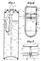
- FIG 1 a classic spray can 1 is shown which is filled with a liquid 2 to be dispersed and in which a pressure capsule 3 according to the invention is installed.
- the pressure capsule 3 as shown in figure 2 can be constructed in any manner by assembling various parts by screwing, welding or similar.
- the pressure capsule in figure 2 is however shown as being of one unit.
- the pressure capsule 3 in this embodiment principally consists of two chambers, respectively 4 and 5, of which the first chamber 4 is intended to be filled with a fluid under relatively high pressure and of which the second chamber 5 is intended to be filled with a fluid under a pressure which is equal or almost equal to the over pressure which is normally applied in a spray can 1.
- a valve 7 is provided in the wall 6 of the first chamber, while in the second chamber 5 a wall 8 is installed which is provided with a membrane 9 that bears a rod 10 to which the valve 7 is attached. From the preceding it follows that the walls in which, on the one hand, the valve 7 and, on the other hand, the membrane 9 are installed, are located opposite each other whereby the space 11 between the walls 6 and 8 is in permanent communication to the vicinity of the pressure capsule 3, in this case via a small hole 12.
- the chambers 4 and 5 each show an opening, respectively 13, 14, which can be closed by suitable sealings means 15, 16.
- the valve 7 is in this case formed by, on the one hand, the aforementioned rod 10 which is attached by one extremity to the membrane 9, whereby this rod passes through an opening in the wall 6 and underneath shows a peripheral groove 17, which for example is produced in a diabolo shape and, on the other hand, a sealing ring 18 which is installed in the aforementioned opening in the wall 6 and which functions as seat for the valve 7.
- the inner diameter of the sealing ring 18, which is produced in an elastic material, for example rubber or similar, will preferably be somewhat smaller than the outer diameter of the rod 10 whereby the sealing ring 18 is placed in the aforementioned peripheral groove 17.
- the first chamber 4 is filled with a fluid under high pressure, for example of the order of 30 kg/cm2, such as compressed air or another gas, preferably, but not necessarily, an inert gas, after which the opening 13 is sealed off with suitable means, such as by gluing, by welding, by a screw plug or similar 15.
- a fluid under high pressure for example of the order of 30 kg/cm2
- compressed air or another gas preferably, but not necessarily, an inert gas
- the chamber 5 is likewise filled via the opening 14 with compressed air or another fluid up to an over pressure which is approximately equal to the desired operating pressure in the spray can 1, whereby this operating pressure is for example of the order of 3 kg/cm2.
- this operating pressure is for example of the order of 3 kg/cm2.
- the pressure capsule 3 as described above can be utilized very advantageously in a spray can 1 filled with liquid 2 in order to supply the pressure medium, in this case air, that serves to remove the liquid 2 from the spray can 1 via an ascending tube 19 and controlled through a valve 21 operatable by means of a press button 20.
- the pressure medium in this case air
- the pressure capsule 3 is installed in the spray can 1, prior to, during or after the filling of the spray can 1 with liquid 2 and prior to the installation of the cover 22 with the ascending tube 19 and the valve 21, after which according to the invention the spray can 1, such as this is the case with traditional spray cans, is brought up to operating pressure, in other words up to a pressure which is equal to or is somewhat higher than the pressure in the chamber 5.
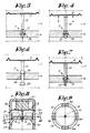
- valve 7 is formed by sealing elements for example in the form of a frustum of a cone, respectively 24 and 25, which can alternatively close off the opening 26 in the wall 6.
- valve 7 is formed by an oblique passage 27 which can move under or above the sealing ring 18 when the valve 7 is closed, and just at the height of the sealing ring 18 when the valve 7 is opened.
- FIG. 8 An embodiment is shown schematic manner in figures 8 and 9 whereby the lower chamber 4 consists of an upper part 28 and a lower part 29 which fit together suitably and are connected to each other by gluing, welding or similar 30 and whereby the upper chamber also consists of two parts, respectively 31 and 32, which are connected to each other in suitable manner by gluing or welding 33 with insertion of the wall 8 of the membrane 9.
- part 31 of the chamber 5 shows as it were four small legs 34 which underneath show an inwardly directed tooth shaped projection 35 which can work together, by clipping in, behind the edge 36 of the part 28 of the chamber 4.
- the opening 12 is formed between the aforementioned small legs 34.
- the pressure in the chamber 5 can be formed in wathever manner and need not necessarily be built up by means of a fluid. Indeed the pressure above the membrane 9 could also be formed by a suitable spring or similar for example an elastic material such as among others a small block of foam rubber 37.
- figure 10 Another embodiment variant is shown in figure 10 which is based on a single chamber pressure capsule.
- the membrane 9 is replaced by a stiff disk shaped element 38 provided at the extremity of the rod 10, whereby between the wall 6 of the chamber 4 and the aforementioned element 38 an elestic element 39 is installed, of foam material, with closed cells, whereby the elasticity of the element 39 corresponds to the so-called reference pressure in the chamber 5 of the embodiment according to figure 2.
- the pressure which is present in the cells, will be chosen or determined in relation to the operating pressure in the spray can 1.
- a small annular block of foam material 39 is provided in which at least one groove, passage or similar 40 is made, whereby this small block 39 is attached to, on the one hand, the wall 6 and, on the other hand, the disk shaped element 38, for example by gluing or another attachment.
- the attachment of the small block 39 and the valve could for example also be effected by extending the housing of the pressure capsule to above the aforementioned extremity as in shown in dotted line in figures 10 and 12, so that the upper position of the small block 39 is determined by the presence of the ring 41.
- FIG 10 the position of the air pressure capsule is shown when this is in an atmospheric envirroment.
- the lower part of the valve 7 closes off the chamber 4 and ring 39 is in released position, whereby the pressure of the ring 39 or similar on the disk shaped element 38 is approximately equal to atmospheric pressure, whereby the pressure in the closed cells of the ring 39 amounts to one bar.
Landscapes
- Chemical & Material Sciences (AREA)
- Dispersion Chemistry (AREA)
- Engineering & Computer Science (AREA)
- Mechanical Engineering (AREA)
- Containers And Packaging Bodies Having A Special Means To Remove Contents (AREA)
- Nozzles (AREA)
Description
- This invention relates to a pressure capsule of the type according to the preamble of claim 1 as well as a spray can which utilizes such a pressure capsule.
- The present invention more especially relates to a pressure capsule which prior to or during the filling of a spray can or similar is installed in the latter and offers the possibility of possibly making use of, either compressed air, or an inert gas as means of propulsion for such spray can, all of which such that a spray can is obtained which has no detrimental effect on the environment and which furthermore has the possibility and the simplicity of operation which at the moment are only to be found with spray cans with the known harmful proppellants
- From document EP-A-0349053 of Applicant a pressure capsule is already known which corresponds to the preamble of claim 1 and which principally consists of at least two chambers of which the first is intended to be filled with a fluid under relatively high pressure and of which the second is intended to be filled with a fluid up to a pressure almost equal to the over pressure which normally exists in a spray can and which is necessary for expelling a liquid; in the wall of the first chamber a valve; in the wall of the second chamber a membrane that can command the aforementioned valve; and a removable element that in its unremoved position holds the valve closed.
- With this known pressure capsule the aforementioned removable element can directly or indirectly act on the valve in order to hold this closed and preferably consists of a material meltable by little heat, all of which such that, after the aforementioned removable element is removed, the aforementioned valve is so regulated by the membrane that fluid is released from the first chamber as long as the pressure in the vicinity of the pressure capsule decreases or at least is notably lower than the pressure in the second chamber of the pressure capsule.
- Although this known pressure capsule works very efficiently the present invention relates to a pressure capsule which still shows considerable additional advantages.
- A first advantage of the pressure capsule according to the invention is that no removable element is necessary so that heating of the spray can, with the intention of melting away the removable element, is no longer necessary.
- Another advantage of the pressure capsule according to the invention is that in the spray can, after the pressure capsule is installed therein, a specific pre-pressure is provided, preferably at least the operating pressure of the spray can, through which the aforementioned pressure capsule can remain smaller because of the fact that less pressure fluid is necessary in the pressure capsule so that consequently the material costs are also lower.
- Yet another advantage of the pressure capsule according to the invention is the very great safety of a spray can equipped with such pressure capsule since, with a possible tearing, leakage or similar of the spray can, the pressure capsule automatically closes, since at that moment the pressure around the pressure capsule drops.
- Another advantage of the pressure capsule according to the invention is that it is no longer necessary, which is the case with a pressure capsule with removable element, during its manufacture, to determine the correct location of the small hole that the removable element must receive, since the opening or passage of the pressure capsule which is in contact with the environment can be provided in any manner and in any place, so that a difficult orientation operation can be omitted.
- Another advantage still of the pressure capsule according to the invention is that the dimensions of the aforementioned opening or passage have no importance with regard to the operation of the pressure capsule.
- Yet another advantage of the pressure capsule according to the invention is ultimately that it is extremely simple to realize, either as dual chamber pressure capsule, or as single chamber pressure capsule.
- The pressure capsule according to the invention which shows the aforementioned and other advantages principally consists of at least one chamber which is intended to be filled with fluid under relatively high pressure; a valve in a wall of the chamber, whereby the rod of the valve is attached either to a membrane in a second chamber, or to a disk shaped extremity of an element; and a pressure regulator having means which command the valve, characterized in that said valve is provided with two spaced apart sealing positions, the pressure regulator means causing the valve to be sealed in the first sealing position when the valve is closed in an atmospheric environment and causing the valve to be sealed in the second position when the valve is closed in an environment where the pressure is greater than or equal to the operating pressure in the spray can, i.e. the pressure which is necessary for the expulsion of a liquid; and whereby the space between either the wall of the chamber intended to be filled with fluid under relatively high pressure and the wall of the membrane, or the wall of the chamber intended to be filled with fluid under relatively high pressure and the disk shaped extremity, is in permanent communication with the environment.
- In order to show better the characteristics according to the present invention, some preferred embodiments are described hereafter, as examples and without any restrictive character with reference to the enclosed drawings in which:
- figure 1 shows a spray can in which a pressure capsule according to the invention is utilized;
- figure 2 shows on larger scale a section of a pressure capsule according to the invention, more especially according to line II-II in figure 1;
- figure 2 shows on larger scale the part that is indicated by F3 in figure 2;
- figures 4 and 5 are similar views to that from figure 3 but for two other characteristic positions;
- figures 6 and 7 show variants of figure 3;
- figure 8 shows a practical embodiment of a pressure capsule according to the invention;
- figure 9 shows a section according to line IX-IX in figure 8;
- figure 10 shows another variant of a pressure capsule according to the invention;
- figure 11 shows a top view of figure 10;
- figure 12 shows a second position of figure 10.
- In figure 1 a classic spray can 1 is shown which is filled with a liquid 2 to be dispersed and in which a
pressure capsule 3 according to the invention is installed. - The
pressure capsule 3, as shown in figure 2, can be constructed in any manner by assembling various parts by screwing, welding or similar. For simplicity the pressure capsule in figure 2 is however shown as being of one unit. - The
pressure capsule 3 in this embodiment principally consists of two chambers, respectively 4 and 5, of which thefirst chamber 4 is intended to be filled with a fluid under relatively high pressure and of which thesecond chamber 5 is intended to be filled with a fluid under a pressure which is equal or almost equal to the over pressure which is normally applied in a spray can 1. - A
valve 7 is provided in thewall 6 of the first chamber, while in the second chamber 5 awall 8 is installed which is provided with amembrane 9 that bears arod 10 to which thevalve 7 is attached. From the preceding it follows that the walls in which, on the one hand, thevalve 7 and, on the other hand, themembrane 9 are installed, are located opposite each other whereby thespace 11 between thewalls pressure capsule 3, in this case via asmall hole 12. - in the embodiment according to figure 2 the
chambers - The
valve 7 is in this case formed by, on the one hand, theaforementioned rod 10 which is attached by one extremity to themembrane 9, whereby this rod passes through an opening in thewall 6 and underneath shows aperipheral groove 17, which for example is produced in a diabolo shape and, on the other hand, asealing ring 18 which is installed in the aforementioned opening in thewall 6 and which functions as seat for thevalve 7. - The inner diameter of the
sealing ring 18, which is produced in an elastic material, for example rubber or similar, will preferably be somewhat smaller than the outer diameter of therod 10 whereby thesealing ring 18 is placed in the aforementionedperipheral groove 17. - According to the invention, for example via the
opening 13, thefirst chamber 4 is filled with a fluid under high pressure, for example of the order of 30 kg/cm2, such as compressed air or another gas, preferably, but not necessarily, an inert gas, after which theopening 13 is sealed off with suitable means, such as by gluing, by welding, by a screw plug or similar 15. - The
chamber 5 is likewise filled via theopening 14 with compressed air or another fluid up to an over pressure which is approximately equal to the desired operating pressure in the spray can 1, whereby this operating pressure is for example of the order of 3 kg/cm². Once at this pressure thechamber 5 will be sealed off bymeans 16, such as for example by gluing, by welding, by a screw plug or similar. - The
pressure capsule 3 as described above can be utilized very advantageously in a spray can 1 filled with liquid 2 in order to supply the pressure medium, in this case air, that serves to remove the liquid 2 from the spray can 1 via anascending tube 19 and controlled through avalve 21 operatable by means of apress button 20. - For this purpose the
pressure capsule 3 is installed in the spray can 1, prior to, during or after the filling of the spray can 1 with liquid 2 and prior to the installation of thecover 22 with theascending tube 19 and thevalve 21, after which according to the invention the spray can 1, such as this is the case with traditional spray cans, is brought up to operating pressure, in other words up to a pressure which is equal to or is somewhat higher than the pressure in thechamber 5. - Because of this it is achieved that the
membrane 9, under influence of the pressure in thespace 23 above the liquid 2, on the one hand, and the small additional pressure of the fluid in thechamber 4 at the extremity of therod 10, on the other hand, in figure 2 moves upwards through which the sealingelement 10 moves out of the position as shown in figure 3 to the position as shown in figure 4, with as result that compressed air or similar escapes out of thechamber 4 through theopening 12 into thespace 23, all of which such that the upward pressure P on themembrane 9 increases with ultimately as result that themembrane 9 is placed in the position as shown in figure 5, in other words in the position whereby thevalve 7 in its second position works together with thesealing ring 18 so that removal of compressed air fromchamber 4 towards thespace 23 is stopped. - When at this time, through the depression of the
press button 20, liquid 2 is dispersed under influence of the pressure of the fluid in thechamber 23, the pressure in thespace 23 will decrease until an equilibrium is reached with-the pressure inchamber 5 of thepressure capsule 3, through which the membrane moves downward and thevalve 7 comes into the position of figure 4. - It is clear that at this time compressed air escapes out of
chamber 4 towards thespace 23 through which the pressure P on themembrane 9 again increases so that, when the force exerted under themembrane 9 becomes greater than the force above the membrane, the latter again moves upwards in order to close off the supply of compressed air from thechamber 4 towards thechamber 23, as shown in figure 5. - In figure 6 an embodiment variant is shown whereby the
valve 7 is formed by sealing elements for example in the form of a frustum of a cone, respectively 24 and 25, which can alternatively close off theopening 26 in thewall 6. - An embodiment is shown in figure 7 whereby the
valve 7 is formed by anoblique passage 27 which can move under or above thesealing ring 18 when thevalve 7 is closed, and just at the height of thesealing ring 18 when thevalve 7 is opened. - An embodiment is shown schematic manner in figures 8 and 9 whereby the
lower chamber 4 consists of an upper part 28 and alower part 29 which fit together suitably and are connected to each other by gluing, welding or similar 30 and whereby the upper chamber also consists of two parts, respectively 31 and 32, which are connected to each other in suitable manner by gluing or welding 33 with insertion of thewall 8 of themembrane 9. - In this embodiment the
part 31 of thechamber 5 shows as it were foursmall legs 34 which underneath show an inwardly directed tooth shapedprojection 35 which can work together, by clipping in, behind theedge 36 of the part 28 of thechamber 4. - In this case the opening 12 is formed between the aforementioned
small legs 34. - It is clear that the pressure in the
chamber 5 can be formed in wathever manner and need not necessarily be built up by means of a fluid. Indeed the pressure above themembrane 9 could also be formed by a suitable spring or similar for example an elastic material such as among others a small block offoam rubber 37. - Another embodiment variant is shown in figure 10 which is based on a single chamber pressure capsule.
- With this only the
chamber 4 is provided which as with the dual chamber pressure capsule described above is filled with a fluid under relatively high pressure. - In this case the
membrane 9 is replaced by a stiff diskshaped element 38 provided at the extremity of therod 10, whereby between thewall 6 of thechamber 4 and theaforementioned element 38 anelestic element 39 is installed, of foam material, with closed cells, whereby the elasticity of theelement 39 corresponds to the so-called reference pressure in thechamber 5 of the embodiment according to figure 2. The pressure which is present in the cells, will be chosen or determined in relation to the operating pressure in the spray can 1. - In the embodiment according to figure 10 a small annular block of
foam material 39 is provided in which at least one groove, passage or similar 40 is made, whereby thissmall block 39 is attached to, on the one hand, thewall 6 and, on the other hand, the disk shapedelement 38, for example by gluing or another attachment. - The attachment of the
small block 39 and the valve could for example also be effected by extending the housing of the pressure capsule to above the aforementioned extremity as in shown in dotted line in figures 10 and 12, so that the upper position of thesmall block 39 is determined by the presence of thering 41. - In figure 10 the position of the air pressure capsule is shown when this is in an atmospheric envirroment. The lower part of the
valve 7 closes off thechamber 4 andring 39 is in released position, whereby the pressure of thering 39 or similar on the disk shapedelement 38 is approximately equal to atmospheric pressure, whereby the pressure in the closed cells of thering 39 amounts to one bar. - When the air pressure capsule according to figure 10 is inserted into a spray can 1 and the latter is brought up to operating pressure, the pressure exerted on the
element 38 will be such that theseal 10 moves into thechamber 4 whereby the disk shapedelement 38 presses on the spring, small block of foam material or similar 39 and brings this into the position as shown in figure 12, whereby thevalve 7 is again closed off. - When now, through the spraying of the liquid, the pressure in the spray can 1 slowly decreases, the
valve 7, respectively therod 10 with the disk shapedelement 38, will again move upwards under influence of the expansion effect of the small block or similar 39. Because of this an amount of compressed air can escape out of thechamber 4 along thevalve 7 and arrive in thespace 23 in the spray can 1 so that, just as with the preceding embodiment, the pressure in thespace 23 again increases until thevalve 7 again closes off thespace 4. - It is clear that, through the correct choice of the material for the
small block 39 or similar, on the one hand, and the surface area of the disk shapedelement 38, on the other hand, the operating pressure in thespace 23 of the spray can 1 can be determined.
Claims (26)
- Pressure capsule for a spray can whereby the pressure capsule consists of at least one chamber (4) which is intended to be filled with fluid under relatively high pressure; a valve (7) in a wall (6) of the chamber (4), whereby the rod (10) of the valve (7) is attached either to a membrane (9) in a second chamber (5), or to a disk shaped extremity (38) of an element; and a pressure regulator having means (5,37,39) which command the valve (7), characterized in that said valve rod (10) is provided with two spaced apart sealing positions, the pressure regulator means (5,37,39) causing the valve (7) to be sealed in the first sealing position when the valve (7) is closed in an atmospheric environment and causing the valve (7) to be sealed in the second position when the valve (7) is closed in an environment where the pressure is greater than or equal to the operating pressure in the spray can, i.e. the pressure which is necessary for the expulsion of a liquid (2); and whereby the space (11) between either the wall (6) of the chamber (4) intended to be filled with fluid under relatively high pressure and the wall (8) of the membrane (9), or the wall (6) of the chamber (4) intended to be filled with fluid under relatively high pressure and the disk shaped extremity (38), is in permanent communication with the environment.
- Pressure capsule according to claim 1, characterized in that it principally consists of two chambers (4,5); in a wall (6) of the first chamber (4) a valve (7); in the second chamber (5) a membrane (9) that can command the valve (7); whereby the first chamber (4) is intended to be filled with a fluid under relatively high pressure and whereby the second chamber (5) is intended to exert a pressure on the membrane (9) which is equal to or almost equal to the over pressure which normally prevails in a spray can (1) and which is necessary for the expulsion of the liquid (2); and whereby the valve (7) has a rod (10) which is attached to the membrane (9) and the space (11) between the wall (6) provided with the valve (7) and the membrane (9) is in permanent communication with the environment.
- Pressure capsule according to claim 1, characterized in that it principally consists of a chamber (4) which is intended to be filled with a fluid under relatively high pressure; in the wall (6) of this chamber (4) a valve (7) having a rod (10) which extends outside the chamber (4); and between the free extremity of the rod (10) and the aforementioned wall (6) an element (39) of elastic material that is intended to exert a pressure on the valve (7) which is equal to atmospheric pressure; whereby the rod (10) of the valve (7) is provided on its free extremity with a stiff disk shaped element (38) that rests on the element (39) of elastic material.
- Pressure capsule according to claim 2, characterized in that the chambers (4,5) are placed coaxially above each other.
- Pressure capsule according to any of the preceding claims, characterized in that the valve (7) comprises a rod (10) which passes through an opening in said wall (6), whereby this rod, at the location of the wall (6), respectively in the wall (6), directly or indirectly works together with the latter in order to form the aforementioned valve (7).
- Pressure capsule according to one of the preceding claims, characterized in that the valve (7) is formed by, on the one hand, a rod (10) having a peripheral groove (17), said rod (10) extending through an opening in the wall of the chamber (4) which is intended to be filled with the fluid which has to be expelled, and, on the other hand, a sealing ring (18) which is installed in said opening, said peripheral groove (17) and said sealing ring (18) cooperating with each other.
- Pressure capsule according to claim 6, characterized in that the aforementioned peripheral groove (17) shows the form of a diabolo.
- Pressure capsule according to one of the claims 1 to 5, characterized in that the valve (7) is formed by a sealing ring (18) which is installed in the opening in the abovesaid wall (6), a rod (10) passing through said opening and an oblique passage (27) in the rod (10) which can be situated above, under or just at the location of the sealing ring (18).
- Pressure capsule according to claim 6, 7 or 8, characterized in that the inner diameter of the sealing ring (18) is smaller than the outer diameter of the rod (10).
- Pressure capsule according to claim 6, 7, 8 or 9, characterized in that the sealing ring (18) is produced in an elastic material, for example rubber.
- Pressure capsule according to any of the claims 1 to 5, characterized in that the valve (7) is formed by a rod (10) which is provided, on the one side, and, on the other side of the wall (6), with an actual sealing element (24,25) that can work together with the opening (26) in the wall (6) in order to close this off, whereby the distance between the elements (24,25) is greater than the thickness of the wall (6).
- Pressure capsule according to claim 2, characterized in that the pressure in the second chamber (5) is obtained by means of a fluid.
- Pressure capsule according to claim 2, characterized in that the pressure in de second chamber (5) is obtained by means of an elastic material (37), installed between the aforementioned membrane (9) and the wall of the second chamber (5) lying opposite.
- Pressure capsule according to claim 13, characterized in that the elastic material (37) is formed by a spring.
- Pressure capsule according to claim 13, characterized in that the elastic material (37) is formed by a small block of foam rubber.
- Pressure capsule according to claim 2, characterized in that one of the chambres (4,5) is provided with one or more legs (34) which underneath show an inwardly directed tooth (35), whereby these teeth (35) can work together with an edge (36) on the other chamber.
- Pressure capsule according to any of claims 2 to 16, characterized in that each chamber (4,5) is formed out of two parts which are connected to each other by gluing, welding or similar.
- Pressure capsule according to claim 2, characterized in that the space (11) between the wall (6) of the chamber (4) and the membrane (9) of the pressure capsule is in communication with the environment by means of a small hole (12).
- Pressure capsule according to claim 16, characterized in that the space (11) between the wall (6) of the chamber (4) and the membrane (9) of the pressure capsule is in communication with the environment by means of passages (12) between said legs (34).
- Pressure capsule according to claim 3, characterized in that the element (39) in elastic material is formed by a small block of foam rubber, with closed cell structure.
- Pressure capsule according to claim 20, characterized in that the element (39) in elastic material in released position exerts a pressure on the valve (7) which is equal to atmospheric pressure.
- Pressure capsule according to claim 20 or 21 characterized in that the pressure in the cells amounts to one bar.
- Pressure capsule according to any of claims 3, 20, 21 or 22, characterized in that at least one passage, channel or similar (40) is provided in said elastic element (39).
- Pressure capsule according to any of claims 3, 20, 21, 22 or 23, characterized in that an annular stop (41) is provided above the disk shaped element (38) of the valve (7).
- Pressure capsule according to any of the claims 3, 20,21,22 or 23, characterized in that the elastic element (39) is attached to said wall (6) and the disk shaped element (38) of the valve (7).
- Pressure capsule according to claim 25, characterized in that the elastic element (39) is attached to said wall (6) and to the disk shaped element (38) of the valve (7) by gluing.
Applications Claiming Priority (2)
| Application Number | Priority Date | Filing Date | Title |
|---|---|---|---|
| BE9000156 | 1990-02-09 | ||
| BE9000156A BE1003682A3 (en) | 1990-02-09 | 1990-02-09 | Drukkapsule for aerosol aerosol and those applying such drukkapsule. |
Publications (2)
| Publication Number | Publication Date |
|---|---|
| EP0446973A1 EP0446973A1 (en) | 1991-09-18 |
| EP0446973B1 true EP0446973B1 (en) | 1994-04-06 |
Family
ID=3884671
Family Applications (1)
| Application Number | Title | Priority Date | Filing Date |
|---|---|---|---|
| EP19910200138 Expired - Lifetime EP0446973B1 (en) | 1990-02-09 | 1991-01-24 | Pressure capsule for spray can |
Country Status (10)
| Country | Link |
|---|---|
| US (1) | US5285931A (en) |
| EP (1) | EP0446973B1 (en) |
| JP (1) | JP3055953B2 (en) |
| CN (1) | CN1023635C (en) |
| AU (1) | AU639747B2 (en) |
| BE (1) | BE1003682A3 (en) |
| CA (1) | CA2034942A1 (en) |
| DE (1) | DE69101573T2 (en) |
| IE (1) | IE61523B1 (en) |
| RU (1) | RU1838208C (en) |
Families Citing this family (36)
| Publication number | Priority date | Publication date | Assignee | Title |
|---|---|---|---|---|
| FR2689866B1 (en) * | 1992-04-09 | 1994-06-17 | Oreal | PROCESS FOR MAKING AN EXTEMPORANEOUS MIXTURE OF AT LEAST TWO COMPONENTS, LIQUID OR PASTY, AND PRESSURIZED CAN FOR IMPLEMENTING SUCH A PROCESS. |
| FR2690142B1 (en) * | 1992-04-17 | 1995-11-17 | Oreal | PRESSURIZED CONTAINER, ESPECIALLY AN AEROSOL CASE, FOR THE DISPENSING UNDER PRESSURE OF A LIQUID OR PASTY COMPONENT. |
| BE1006130A3 (en) * | 1992-08-19 | 1994-05-17 | Belgium Spray Accessory Factor | Aerosol. |
| ES2105627T3 (en) * | 1993-01-25 | 1997-10-16 | Cpb Innovative Tech Ltd | PACKAGES AND CONTAINERS FOR BEVERAGES. |
| NL1000541C2 (en) | 1995-06-09 | 1996-12-10 | Ver Coop Melkind | Liquid and pasty foods in aerosol. |
| BE1010074A6 (en) * | 1996-04-02 | 1997-12-02 | Belgium Spray Accessory Factor | METHOD AND APPARATUS FOR GENERATING PRESSURE IN AN AEROSOL AND THE LIKE, AND AEROSOL EQUIPPED WITH SUCH ANY DEVICE. |
| BE1010131A3 (en) * | 1996-04-02 | 1998-01-06 | Belgium Spray Accessory Factor | METHOD AND APPARATUS FOR GENERATING PRESSURE IN AN AEROSOL AND THE LIKE, AND AEROSOL EQUIPPED WITH SUCH ANY DEVICE. |
| EP0844197A1 (en) * | 1996-11-25 | 1998-05-27 | The Procter & Gamble Company | Gas generating unit |
| AUPP211298A0 (en) * | 1998-03-03 | 1998-03-26 | Dinco Trading Pty Ltd | Pressure regulating device for pressurised vessel |
| NL1008601C2 (en) * | 1998-03-16 | 1999-09-17 | Heineken Tech Services | Device for dispensing a fluid. |
| NL1009292C1 (en) * | 1998-05-29 | 1999-11-30 | Packaging Tech Holding Sa | Pressure control device for maintaining a constant predetermined pressure in a container. |
| HK1042885B (en) * | 1998-12-16 | 2004-08-06 | 海尼肯技术服务有限公司 | Container for storing and dispensing beverage, in particular beer |
| CN1131825C (en) * | 1998-12-16 | 2003-12-24 | 海尼肯技术服务有限公司 | Container with pressure control device for dispensing fluid |
| NL1012754C2 (en) * | 1999-07-30 | 2001-02-01 | Presstech N V | Pressure control device. |
| AUPS023702A0 (en) * | 2002-01-31 | 2002-02-21 | Fraser-Easton, Gilbert | Pressure regulating device for a pressurised dispensing vessel |
| NL1022455C2 (en) * | 2003-01-21 | 2004-07-22 | Packaging Tech Holding Sa | System for applying a working pressure to a content of a pressure package with the aid of a propellant. |
| NL1022456C2 (en) * | 2003-01-21 | 2004-07-22 | Packaging Tech Holding Sa | Pressure package system for applying a working pressure to a fluid contained in a pressure package. |
| NL1023968C2 (en) * | 2003-07-21 | 2005-01-24 | Heineken Tech Services | Pressure regulator for carbonated beverage container. |
| AU2004316447B2 (en) * | 2004-01-30 | 2010-04-22 | Ips Patent Ag | Pressure control device |
| NL1027998C2 (en) * | 2005-01-11 | 2006-07-12 | Heineken Tech Services | Pressure control device for a container and container provided with such a pressure control device. |
| CA2603909A1 (en) * | 2005-04-08 | 2006-10-12 | Multi-Vet Ltd. | Aerosol dispenser with venturi effect spray nozzle |
| FR2899210A1 (en) * | 2006-03-30 | 2007-10-05 | Ad Venta Sarl | Pneumatic component for micro-diffusion of e.g. perfume, has fixation system forming intermediate chamber between piston and upper part of container, where body has orifice communicating with chamber when body is fixed on container |
| CN101568390B (en) * | 2006-11-22 | 2013-06-19 | 卡尔贡碳公司 | Carbon-filled pressure vessel and method of manufacture |
| US7779608B2 (en) * | 2007-02-02 | 2010-08-24 | Lim Walter K | Pressurized containers and methods for filling them |
| US8066156B2 (en) * | 2008-05-21 | 2011-11-29 | Millercoors Llc | Beverage dispensing device |
| EP2405164A1 (en) * | 2010-07-08 | 2012-01-11 | Anheuser-Bush Inbev NV | Resilient closure for pressure driven dispensing container |
| MX2013009376A (en) * | 2011-02-14 | 2014-03-27 | Heineken Supply Chain Bv | METHOD AND APPARATUS FOR PACKING DRINKS UNDER PRESSURE. |
| EP2707149A4 (en) * | 2011-05-09 | 2014-12-03 | Dispensing Technologies Bv | ISOLATION OF PRODUCT AND PROPULSION AGENT IN VARIOUS PLATFORMS AND DISPENSING DEVICES ("FLAIRFRESH") |
| WO2013016387A1 (en) * | 2011-07-25 | 2013-01-31 | Mccreery David | Corrosion-inhibiting lubricant and methods therefor |
| EP3250476B1 (en) * | 2015-01-27 | 2018-08-29 | Airopack Technology Group B.V. | Pressure control system |
| MX388179B (en) * | 2015-01-28 | 2025-03-19 | Airopack Tech Group B V | PRESSURE CONTROL SYSTEM. |
| MX2017014454A (en) * | 2015-05-12 | 2018-09-06 | Basf Coatings Gmbh | Safety and control device for pressurized containers, and pressurized container having such a safety and control device. |
| NL2020756B1 (en) * | 2018-04-12 | 2019-10-23 | Heineken Supply Chain Bv | Pressure regulating system for a beverage container and beverage container provided therewith |
| NL2023563B1 (en) * | 2019-07-24 | 2021-02-10 | Heineken Supply Chain Bv | Pressure regulating system for a beverage container and beverage container provided therewith |
| CN113565959B (en) * | 2021-08-11 | 2024-03-19 | 国网上海市电力公司 | A cabin-passing sealing structure and cloud platform |
| CN116066717B (en) * | 2023-01-12 | 2023-06-20 | 江苏皓宇特种设备制造有限公司 | Pressure vessel with internal supercharging device |
Family Cites Families (12)
| Publication number | Priority date | Publication date | Assignee | Title |
|---|---|---|---|---|
| US1349443A (en) * | 1918-02-02 | 1920-08-10 | Reuben C Stokes | Reducing-valve |
| US2794579A (en) * | 1954-03-31 | 1957-06-04 | Seaquist Mfg Corp | Aerosol bomb having spaced propellant and dispensable liquids |
| US3243085A (en) * | 1962-07-05 | 1966-03-29 | Reynolds Metals Co | Dispensing container having a gas pressure container therein |
| US3258163A (en) * | 1964-08-04 | 1966-06-28 | Edward E Brush | Low pressure dispensing container |
| US3468137A (en) * | 1967-10-30 | 1969-09-23 | Vendo Co | Method and apparatus for freezing and dispensing slush carbonated beverages |
| US3613954A (en) * | 1968-06-20 | 1971-10-19 | Schlitz Brewing Co J | Dispensing apparatus |
| US3815793A (en) * | 1969-06-10 | 1974-06-11 | Oreal | Pressurized dispenser holding more highly pressurized internal container |
| GB1390937A (en) * | 1971-04-23 | 1975-04-16 | Unilever Ltd | Pressurised aerosol dispensing device |
| US4049158A (en) * | 1975-11-13 | 1977-09-20 | S. C. Johnson & Son, Inc. | Pressurized container-dispensers and filling method |
| US4399158A (en) * | 1978-06-20 | 1983-08-16 | General Foods Corporation | Pressurized container providing for the separate storage of a plurality of materials |
| ATE77338T1 (en) * | 1988-06-29 | 1992-07-15 | Jaico Cv | PRESSURE CAPSULE FOR SPRAY TANK, AND SPRAY TANK USING SUCH CAPSULE. |
| US5110014A (en) * | 1990-11-07 | 1992-05-05 | Doundoulakis George J | Bi-stable pressure maintaining gas containers |
-
1990
- 1990-02-09 BE BE9000156A patent/BE1003682A3/en active
-
1991
- 1991-01-24 EP EP19910200138 patent/EP0446973B1/en not_active Expired - Lifetime
- 1991-01-24 DE DE69101573T patent/DE69101573T2/en not_active Expired - Fee Related
- 1991-01-25 CA CA002034942A patent/CA2034942A1/en not_active Abandoned
- 1991-02-01 US US07/648,915 patent/US5285931A/en not_active Expired - Fee Related
- 1991-02-06 AU AU70819/91A patent/AU639747B2/en not_active Ceased
- 1991-02-08 IE IE42691A patent/IE61523B1/en not_active IP Right Cessation
- 1991-02-08 RU SU914894516A patent/RU1838208C/en active
- 1991-02-09 CN CN91100973.6A patent/CN1023635C/en not_active Expired - Fee Related
- 1991-02-12 JP JP3019034A patent/JP3055953B2/en not_active Expired - Lifetime
Also Published As
| Publication number | Publication date |
|---|---|
| EP0446973A1 (en) | 1991-09-18 |
| DE69101573D1 (en) | 1994-05-11 |
| BE1003682A3 (en) | 1992-05-19 |
| IE910426A1 (en) | 1991-08-14 |
| AU639747B2 (en) | 1993-08-05 |
| AU7081991A (en) | 1991-08-15 |
| CN1054020A (en) | 1991-08-28 |
| DE69101573T2 (en) | 1994-07-21 |
| CN1023635C (en) | 1994-02-02 |
| CA2034942A1 (en) | 1991-08-10 |
| JP3055953B2 (en) | 2000-06-26 |
| US5285931A (en) | 1994-02-15 |
| IE61523B1 (en) | 1994-11-16 |
| RU1838208C (en) | 1993-08-30 |
| JPH04215986A (en) | 1992-08-06 |
Similar Documents
| Publication | Publication Date | Title |
|---|---|---|
| EP0446973B1 (en) | Pressure capsule for spray can | |
| EP0050444A1 (en) | Apparatus for applying liquid to a surface | |
| CA2189227C (en) | Sprinkler | |
| EP0337913B1 (en) | Improvements in filler heads of pressurized bottles | |
| KR910000488A (en) | Pressure cans for spray cans and spray cans with pressure capsules | |
| EP2226539B1 (en) | Overpressure- and ventilating valve for an aeration device | |
| EP1442225B1 (en) | Hydraulic device with breather assembly | |
| KR830006610A (en) | Relief valve with new seal | |
| CA2039288C (en) | Main valve and seat for use in filling containers to a predetermined level | |
| WO1999063250A3 (en) | Control device for a safety valve | |
| JP2025504723A (en) | Dual-substance nozzle, spray head, and method | |
| JPS6421282A (en) | Liquid distribution unit | |
| US4142449A (en) | Hydraulic mine prop | |
| JP3342215B2 (en) | Ball tap with pressure balance structure | |
| EP0020352B1 (en) | Pilot operated relief valve | |
| JP2753845B2 (en) | Aerosol container | |
| SU1149765A1 (en) | Pneumatic radiator of acoustic signals in fluid | |
| EP0266007B1 (en) | Piston restraining construction of pressure reducing valve | |
| US4479631A (en) | Hydraulically balanced valve mechanism | |
| US4453560A (en) | Hydraulically balanced valve mechanism | |
| JPS6115288Y2 (en) | ||
| JPH0547656U (en) | Actuator for opening and closing high pressure gas container valve | |
| JPH0411993Y2 (en) | ||
| JPS6221592Y2 (en) | ||
| US4699167A (en) | Electric valve |
Legal Events
| Date | Code | Title | Description |
|---|---|---|---|
| PUAI | Public reference made under article 153(3) epc to a published international application that has entered the european phase |
Free format text: ORIGINAL CODE: 0009012 |
|
| AK | Designated contracting states |
Kind code of ref document: A1 Designated state(s): BE DE FR GB LU NL SE |
|
| 17P | Request for examination filed |
Effective date: 19920311 |
|
| 17Q | First examination report despatched |
Effective date: 19920622 |
|
| GRAA | (expected) grant |
Free format text: ORIGINAL CODE: 0009210 |
|
| AK | Designated contracting states |
Kind code of ref document: B1 Designated state(s): BE DE FR GB LU NL SE |
|
| RAP4 | Party data changed (patent owner data changed or rights of a patent transferred) |
Owner name: JAICO C.V. COOPERATIEVE VENNOOTSCHAP |
|
| REF | Corresponds to: |
Ref document number: 69101573 Country of ref document: DE Date of ref document: 19940511 |
|
| ET | Fr: translation filed | ||
| EAL | Se: european patent in force in sweden |
Ref document number: 91200138.5 |
|
| PLBE | No opposition filed within time limit |
Free format text: ORIGINAL CODE: 0009261 |
|
| STAA | Information on the status of an ep patent application or granted ep patent |
Free format text: STATUS: NO OPPOSITION FILED WITHIN TIME LIMIT |
|
| 26N | No opposition filed | ||
| PGFP | Annual fee paid to national office [announced via postgrant information from national office to epo] |
Ref country code: GB Payment date: 20010122 Year of fee payment: 11 |
|
| PGFP | Annual fee paid to national office [announced via postgrant information from national office to epo] |
Ref country code: SE Payment date: 20010125 Year of fee payment: 11 |
|
| PGFP | Annual fee paid to national office [announced via postgrant information from national office to epo] |
Ref country code: NL Payment date: 20010129 Year of fee payment: 11 Ref country code: FR Payment date: 20010129 Year of fee payment: 11 |
|
| PGFP | Annual fee paid to national office [announced via postgrant information from national office to epo] |
Ref country code: BE Payment date: 20010130 Year of fee payment: 11 |
|
| PGFP | Annual fee paid to national office [announced via postgrant information from national office to epo] |
Ref country code: DE Payment date: 20010206 Year of fee payment: 11 |
|
| REG | Reference to a national code |
Ref country code: GB Ref legal event code: IF02 |
|
| PG25 | Lapsed in a contracting state [announced via postgrant information from national office to epo] |
Ref country code: LU Free format text: LAPSE BECAUSE OF NON-PAYMENT OF DUE FEES Effective date: 20020124 Ref country code: GB Free format text: LAPSE BECAUSE OF NON-PAYMENT OF DUE FEES Effective date: 20020124 |
|
| PG25 | Lapsed in a contracting state [announced via postgrant information from national office to epo] |
Ref country code: SE Free format text: LAPSE BECAUSE OF NON-PAYMENT OF DUE FEES Effective date: 20020125 |
|
| PG25 | Lapsed in a contracting state [announced via postgrant information from national office to epo] |
Ref country code: BE Free format text: LAPSE BECAUSE OF NON-PAYMENT OF DUE FEES Effective date: 20020131 |
|
| BERE | Be: lapsed |
Owner name: JAICO C.V. COOPERATIEVE VENNOOTSCHAP Effective date: 20020131 |
|
| PG25 | Lapsed in a contracting state [announced via postgrant information from national office to epo] |
Ref country code: NL Free format text: LAPSE BECAUSE OF NON-PAYMENT OF DUE FEES Effective date: 20020801 Ref country code: DE Free format text: LAPSE BECAUSE OF NON-PAYMENT OF DUE FEES Effective date: 20020801 |
|
| EUG | Se: european patent has lapsed |
Ref document number: 91200138.5 |
|
| GBPC | Gb: european patent ceased through non-payment of renewal fee |
Effective date: 20020124 |
|
| PG25 | Lapsed in a contracting state [announced via postgrant information from national office to epo] |
Ref country code: FR Free format text: LAPSE BECAUSE OF NON-PAYMENT OF DUE FEES Effective date: 20020930 |
|
| NLV4 | Nl: lapsed or anulled due to non-payment of the annual fee |
Effective date: 20020801 |
|
| REG | Reference to a national code |
Ref country code: FR Ref legal event code: ST |
|
| PGFP | Annual fee paid to national office [announced via postgrant information from national office to epo] |
Ref country code: LU Payment date: 20040610 Year of fee payment: 11 |