EP0446983B1 - Eaves section assembly - Google Patents
Eaves section assembly Download PDFInfo
- Publication number
- EP0446983B1 EP0446983B1 EP91200432A EP91200432A EP0446983B1 EP 0446983 B1 EP0446983 B1 EP 0446983B1 EP 91200432 A EP91200432 A EP 91200432A EP 91200432 A EP91200432 A EP 91200432A EP 0446983 B1 EP0446983 B1 EP 0446983B1
- Authority
- EP
- European Patent Office
- Prior art keywords
- section
- rib
- body part
- covering
- end edge
- Prior art date
- Legal status (The legal status is an assumption and is not a legal conclusion. Google has not performed a legal analysis and makes no representation as to the accuracy of the status listed.)
- Expired - Lifetime
Links
- 239000000463 material Substances 0.000 claims abstract description 11
- 230000001681 protective effect Effects 0.000 claims description 4
- 230000000284 resting effect Effects 0.000 abstract 1
- 230000035515 penetration Effects 0.000 description 2
- 239000012858 resilient material Substances 0.000 description 2
- XLYOFNOQVPJJNP-UHFFFAOYSA-N water Substances O XLYOFNOQVPJJNP-UHFFFAOYSA-N 0.000 description 2
- 239000011248 coating agent Substances 0.000 description 1
- 238000000576 coating method Methods 0.000 description 1
- 239000013013 elastic material Substances 0.000 description 1
- 238000007689 inspection Methods 0.000 description 1
- 238000000034 method Methods 0.000 description 1
- 238000007789 sealing Methods 0.000 description 1
Images


Classifications
-
- E—FIXED CONSTRUCTIONS
- E04—BUILDING
- E04D—ROOF COVERINGS; SKY-LIGHTS; GUTTERS; ROOF-WORKING TOOLS
- E04D13/00—Special arrangements or devices in connection with roof coverings; Protection against birds; Roof drainage ; Sky-lights
- E04D13/15—Trimming strips; Edge strips; Fascias; Expansion joints for roofs
Definitions
- the invention relates to an eaves section assembly such as is described in the preamble to the main claim.
- Such an eaves section assembly is known per se from NL-A-8702662.
- the expansion joint present between the two bottom sections is covered by a covering sheet made of a thin sheet material which is clamped by the flanged end edge around the adjacent end edges of the bottom sections and is forced with its other end, flanged to a U-shape, into the nesting space determined by the L-shaped rib.
- a condition for such a method of sealing is that the two bottom sections between which the space must be sealed lie exactly in line, which hardly ever occurs in practice. Even then, rainwater can gain access through capillary action between the covering section and the bottom section, one result of which is wet patches on the outside wall. Besides, the covering sheet is found in practice to be difficult to fit, and during fitting is found to damage the top surface of the bottom section, which is generally finished with a surface coating. After fitting, removal - for example for inspection purposes - is not possible without damaging the bottom sections.
- the object of the invention is to eliminate these disadvantages, and this is achieved according to the invention with the measures described in the characterizing part of the main claim.
- Removal of the covering section is possible at any time by carrying out the operations for fitting thereof in the reverse order.
- the resilient compressible material primarily ensures locking and the taking up of tolerances, but also prevents damage during fitting and on expansion of the bottom section, and furthermore provides a seal against the penetration of rainwater.
- DE-A-3520640 and NL-A-8702662 disclose the use of compressible material in an eaves section assembly, but for a quite different purpose and in a different configuration, only to prevent the ingress of water.
- the section assembly according to the invention, indicated in the figures in its entirety by the reference number 2, comprises a bottom section 4 and a covering section 6 to be placed thereon.
- the bottom section 4 comprises a body part 8 with two supporting ribs 10, 12 going out from the bottom side thereof, which body part 8 bears at the front side a protective strip 14 which is provided with supporting ribs 16, 18 by means of which the protective strip 14 rests against the raised edge 20 of the roof 22 with the roof covering 24 fitted thereon.
- the protective strip 14 extends past the body part 8 into a part 14a which merges into an end edge 26, so that in fact an L-shaped rib 28 goes out from the body part 8. This produces a nesting space 30 with height h1 above the body part 8.
- An auxiliary rib 32 with end edge 34 goes out from the supporting rib 10, which edge - like the end edges of the ribs 10 and 12 - rests on the roof covering 24 when the section 4 is fitted.
- auxiliary rib 32 Under the auxiliary rib 32 is compressible material 36 which is compressed on fitting of the section after tightening of the fixing screws 38 thereof (see Figure 5).
- the body part 8 projects over a short distance past the rib 10 and ends in a downward directed locking rib 40 with hooked end 42. The purpose of this will be explained later.
- This covering section 6 comprises a sheet-shaped part 46 having at the first end 48 a cross rib 50 and at the second end 52 a flanged end edge 54 which is formed by an edge 46a forming an obtuse angle with the sheet part 46 and a rib 60 with a hooked end 62 going out near the end thereof.
- Resilient, compressible material 64 is provided on the bottom face of the sheet part 46, preferably in the form of elongated strips.
- the thickness of this material is such that the distance h2 between the bottom side of this material and the top end of the rib 50 is greater than the height h1 inside the nesting space 30.
- Figures 3 and 4 show how the covering section 6 is fitted on the bottom section 4: the rib 50 of the covering section 6 is taken into the nesting space 30 while the resilient elastic material 64 is being compressed, and the bottom side of the rib 60 is pressed against the top surface of the auxiliary rib 32. In this case the points of the hooks 62 and 42 are clear of each other, as shown in Figure 3.
- the covering rib 6 is then pressed into the position shown in Figure 4, and the rib 6 is then released: through the resilience of the resilient material 64, the covering section 6 comes up and is securely anchored to the bottom section 4.
- Removal of the covering section is possible at any time by carrying out the operations described above in the reverse order.
Landscapes
- Engineering & Computer Science (AREA)
- Architecture (AREA)
- Civil Engineering (AREA)
- Structural Engineering (AREA)
- Vehicle Interior And Exterior Ornaments, Soundproofing, And Insulation (AREA)
- Roof Covering Using Slabs Or Stiff Sheets (AREA)
Abstract
Description
- The invention relates to an eaves section assembly such as is described in the preamble to the main claim.
- Such an eaves section assembly is known per se from NL-A-8702662. In the case of this known eaves section assembly the expansion joint present between the two bottom sections is covered by a covering sheet made of a thin sheet material which is clamped by the flanged end edge around the adjacent end edges of the bottom sections and is forced with its other end, flanged to a U-shape, into the nesting space determined by the L-shaped rib.
- A condition for such a method of sealing is that the two bottom sections between which the space must be sealed lie exactly in line, which hardly ever occurs in practice. Even then, rainwater can gain access through capillary action between the covering section and the bottom section, one result of which is wet patches on the outside wall. Besides, the covering sheet is found in practice to be difficult to fit, and during fitting is found to damage the top surface of the bottom section, which is generally finished with a surface coating. After fitting, removal - for example for inspection purposes - is not possible without damaging the bottom sections.
- The object of the invention is to eliminate these disadvantages, and this is achieved according to the invention with the measures described in the characterizing part of the main claim.
- For fitting of the covering section designed according to the invention, all that is needed is to compress the resilient, compressible material on the bottom side thereof onto the body part of the bottom section and slide the cross rib of the covering section into the nesting space until the two locking ribs have passed each other; when the covering section is then released, it springs by itself into the desired end position without damage to the bottom section having occurred, and this locked end position is achieved even if the bottom sections are not exactly in line with one another.
- Removal of the covering section is possible at any time by carrying out the operations for fitting thereof in the reverse order.
- The resilient compressible material primarily ensures locking and the taking up of tolerances, but also prevents damage during fitting and on expansion of the bottom section, and furthermore provides a seal against the penetration of rainwater.
- A preferred embodiment of the eaves section assembly is described
claim 2. - It is observed that both DE-A-3520640 and NL-A-8702662 disclose the use of compressible material in an eaves section assembly, but for a quite different purpose and in a different configuration, only to prevent the ingress of water.
- The invention is explained with reference to the drawing, in which:
- Figure 1 is a cross-section through a part of eaves with the bottom section part according to the invention;
- Figure 2 is a cross-section through the covering section with resilient material to be placed thereon;
- Figure 3 is a cross-section of these parts during placing of the covering section on the bottom section;
- Figure 4 is a cross-section of the complete eaves section assembly;
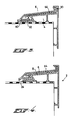
- Figure 5 is a perspective drawing, partially in cross-section, of this complete section assembly.
- The section assembly according to the invention, indicated in the figures in its entirety by the
reference number 2, comprises abottom section 4 and a coveringsection 6 to be placed thereon. - The
bottom section 4 comprises abody part 8 with two supportingribs body part 8 bears at the front side aprotective strip 14 which is provided with supportingribs protective strip 14 rests against the raisededge 20 of theroof 22 with the roof covering 24 fitted thereon. Theprotective strip 14 extends past thebody part 8 into apart 14a which merges into anend edge 26, so that in fact an L-shaped rib 28 goes out from thebody part 8. This produces anesting space 30 with height h1 above thebody part 8. - An
auxiliary rib 32 withend edge 34 goes out from the supportingrib 10, which edge - like the end edges of theribs 10 and 12 - rests on the roof covering 24 when thesection 4 is fitted. - Under the
auxiliary rib 32 iscompressible material 36 which is compressed on fitting of the section after tightening of thefixing screws 38 thereof (see Figure 5). - The
body part 8 projects over a short distance past therib 10 and ends in a downward directedlocking rib 40 with hookedend 42. The purpose of this will be explained later. - On fitting of the bottom sections on the eaves (see Figure 5) an expansion joint 44 must remain free between two
adjacent sections 4a, 4b. In order to prevent water penetration, this joint must be covered, and the coveringsection 6, of which Figure 2 shows a cross-section, serves this purpose. This coveringsection 6 comprises a sheet-shaped part 46 having at the first end 48 across rib 50 and at the second end 52 aflanged end edge 54 which is formed by anedge 46a forming an obtuse angle with thesheet part 46 and arib 60 with ahooked end 62 going out near the end thereof. - Resilient,
compressible material 64 is provided on the bottom face of thesheet part 46, preferably in the form of elongated strips. The thickness of this material is such that the distance h2 between the bottom side of this material and the top end of therib 50 is greater than the height h1 inside thenesting space 30. - Figures 3 and 4 show how the covering
section 6 is fitted on the bottom section 4: therib 50 of thecovering section 6 is taken into thenesting space 30 while the resilientelastic material 64 is being compressed, and the bottom side of therib 60 is pressed against the top surface of theauxiliary rib 32. In this case the points of thehooks covering rib 6 is then pressed into the position shown in Figure 4, and therib 6 is then released: through the resilience of theresilient material 64, thecovering section 6 comes up and is securely anchored to thebottom section 4. - Removal of the covering section is possible at any time by carrying out the operations described above in the reverse order.
- It is clear that there are no limits for the length of the covering
section 6, so that the section assembly can also be made in the form of a so-called "double trim", where the bottom sections are thus covered over their entire length with a covering section.
Claims (2)
- Eave section assembly having section parts for mounting in alignment with each other at the eave of a roof, each with a body part (8) supported by means of ribs (10, 12) destined to rest upon the roof surface (22), and a protective strip (14) provided at right angles to the front end edge intended to extend parallel to the wall surface at said eave, and having near said first end edge, extending away from the roof surface, an L-shaped rib (28), while above two adjacent section parts a covering section (6) covering the space between them is fitted, with at the first end thereof a first cross rib (50) fitting inside the space (30) determined by the body part (8) and the L-shaped rib (28) and at the second end (54) thereof a flange facing in the opposite direction to said cross rib (50), characterized in that the first cross rib (50) fits with ample play inside the space (30) determined by the body part and the L-shaped rib, that near the second end edge (40) of the body part (8) a short locking rib (42) is provided extending downwardly from the body part (8) and thus in a direction opposite to the direction of the body part of the L-shaped rib (28) and running in the lengthwise direction of the second, which rib (42) is intended to grip behind a second locking rib (62) projecting upwards from the flanged end edge (54) of the covering section (6), and that the surface of the covering section (6) facing the body part (8) is provided with resilient, compressible material (64).
- Eaves section assembly according to claim 1, characterized in that the compressible material (64) on the covering section is fitted in the form of elongated strips.
Priority Applications (1)
| Application Number | Priority Date | Filing Date | Title |
|---|---|---|---|
| AT91200432T ATE99373T1 (en) | 1990-03-15 | 1991-02-28 | ROOF EDGE TRIM ARRANGEMENT. |
Applications Claiming Priority (2)
| Application Number | Priority Date | Filing Date | Title |
|---|---|---|---|
| NL9000595 | 1990-03-15 | ||
| NL9000595A NL9000595A (en) | 1990-03-15 | 1990-03-15 | ROOF PROFILE ASSEMBLY. |
Publications (2)
| Publication Number | Publication Date |
|---|---|
| EP0446983A1 EP0446983A1 (en) | 1991-09-18 |
| EP0446983B1 true EP0446983B1 (en) | 1993-12-29 |
Family
ID=19856746
Family Applications (1)
| Application Number | Title | Priority Date | Filing Date |
|---|---|---|---|
| EP91200432A Expired - Lifetime EP0446983B1 (en) | 1990-03-15 | 1991-02-28 | Eaves section assembly |
Country Status (4)
| Country | Link |
|---|---|
| EP (1) | EP0446983B1 (en) |
| AT (1) | ATE99373T1 (en) |
| DE (1) | DE69100860T2 (en) |
| NL (1) | NL9000595A (en) |
Families Citing this family (1)
| Publication number | Priority date | Publication date | Assignee | Title |
|---|---|---|---|---|
| AU638862B2 (en) * | 1990-08-27 | 1993-07-08 | Uniframes Holdings Pty Limited | An eave and fascia |
Family Cites Families (4)
| Publication number | Priority date | Publication date | Assignee | Title |
|---|---|---|---|---|
| DE2913618A1 (en) * | 1979-04-04 | 1980-10-16 | Avg Aluminium Vertriebs Gmbh | Roof verge profile assembly - has clips set on inner profile to hold outer one at interval |
| NL8301857A (en) * | 1983-05-26 | 1984-12-17 | Pierre Eugene Ikking | Eaves flashing strip assembly system - includes clamps with curved edge over which trim strips are clipped |
| DE3520640A1 (en) * | 1985-06-08 | 1986-12-11 | Alural Bauelemente Gmbh & Co Kg, 3203 Sarstedt | Covering for walls, breasts or the like |
| NL8702662A (en) * | 1987-11-06 | 1988-09-01 | Compri Aluminium | ROOF EDGE PROFILE WITH SEAM SEAL. |
-
1990
- 1990-03-15 NL NL9000595A patent/NL9000595A/en not_active Application Discontinuation
-
1991
- 1991-02-28 EP EP91200432A patent/EP0446983B1/en not_active Expired - Lifetime
- 1991-02-28 DE DE69100860T patent/DE69100860T2/en not_active Expired - Fee Related
- 1991-02-28 AT AT91200432T patent/ATE99373T1/en not_active IP Right Cessation
Also Published As
| Publication number | Publication date |
|---|---|
| NL9000595A (en) | 1991-10-01 |
| EP0446983A1 (en) | 1991-09-18 |
| DE69100860D1 (en) | 1994-02-10 |
| DE69100860T2 (en) | 1994-05-26 |
| ATE99373T1 (en) | 1994-01-15 |
Similar Documents
| Publication | Publication Date | Title |
|---|---|---|
| US3977145A (en) | Horizontal siding panel joint support | |
| US4592176A (en) | Roof edging system | |
| US4067152A (en) | Fascia compression clip | |
| RU96119759A (en) | WATERPROOFING DEVICE | |
| HU215339B (en) | Flashing arrangement for mounting of a roof element, in particular a roof window in a roof | |
| US4439956A (en) | Press lock fascia-cant system | |
| EP0010430B1 (en) | Improvements in opening roofs for vehicles | |
| EP0446983B1 (en) | Eaves section assembly | |
| US5193321A (en) | Standing seam paneling system | |
| EP0084909A2 (en) | Means for the protection of the lower edge of an inclined roof covered by scaly elements, like roof tiles | |
| EP1131513B1 (en) | Drainage gutter | |
| EP0365094B1 (en) | Eaves section system | |
| US3992827A (en) | Coping assembly with deformable seal clamp | |
| GB2110734A (en) | Roofing | |
| EP0404814B1 (en) | Roofing sheet | |
| JP4970841B2 (en) | Windbreak decorative board and its mounting structure | |
| EP0994991B1 (en) | A skylight window with attachment collar for a vapour barrier membrane | |
| JP7643745B2 (en) | Vertical roof structure | |
| JPH0310254Y2 (en) | ||
| JP4330441B2 (en) | Weather Strip | |
| JP3447109B2 (en) | Rising part from flat roof | |
| JPS6337363Y2 (en) | ||
| JPH10131414A (en) | Method for connecting building panel | |
| CA2156478A1 (en) | Snap-on coping holddown | |
| GB2401615A (en) | Roof edging strip |
Legal Events
| Date | Code | Title | Description |
|---|---|---|---|
| PUAI | Public reference made under article 153(3) epc to a published international application that has entered the european phase |
Free format text: ORIGINAL CODE: 0009012 |
|
| AK | Designated contracting states |
Kind code of ref document: A1 Designated state(s): AT BE CH DE FR GB LI LU NL |
|
| 17P | Request for examination filed |
Effective date: 19910731 |
|
| 17Q | First examination report despatched |
Effective date: 19920529 |
|
| GRAA | (expected) grant |
Free format text: ORIGINAL CODE: 0009210 |
|
| AK | Designated contracting states |
Kind code of ref document: B1 Designated state(s): AT BE CH DE FR GB LI LU NL |
|
| PG25 | Lapsed in a contracting state [announced via postgrant information from national office to epo] |
Ref country code: FR Effective date: 19931229 Ref country code: AT Effective date: 19931229 Ref country code: CH Effective date: 19931229 Ref country code: LI Effective date: 19931229 |
|
| REF | Corresponds to: |
Ref document number: 99373 Country of ref document: AT Date of ref document: 19940115 Kind code of ref document: T |
|
| REF | Corresponds to: |
Ref document number: 69100860 Country of ref document: DE Date of ref document: 19940210 |
|
| PG25 | Lapsed in a contracting state [announced via postgrant information from national office to epo] |
Ref country code: LU Free format text: LAPSE BECAUSE OF NON-PAYMENT OF DUE FEES Effective date: 19940228 |
|
| REG | Reference to a national code |
Ref country code: CH Ref legal event code: PL |
|
| EN | Fr: translation not filed | ||
| PLBE | No opposition filed within time limit |
Free format text: ORIGINAL CODE: 0009261 |
|
| STAA | Information on the status of an ep patent application or granted ep patent |
Free format text: STATUS: NO OPPOSITION FILED WITHIN TIME LIMIT |
|
| 26N | No opposition filed | ||
| PGFP | Annual fee paid to national office [announced via postgrant information from national office to epo] |
Ref country code: BE Payment date: 19980129 Year of fee payment: 8 |
|
| PGFP | Annual fee paid to national office [announced via postgrant information from national office to epo] |
Ref country code: GB Payment date: 19980202 Year of fee payment: 8 |
|
| PGFP | Annual fee paid to national office [announced via postgrant information from national office to epo] |
Ref country code: DE Payment date: 19980226 Year of fee payment: 8 |
|
| PG25 | Lapsed in a contracting state [announced via postgrant information from national office to epo] |
Ref country code: BE Free format text: LAPSE BECAUSE OF NON-PAYMENT OF DUE FEES Effective date: 19990228 Ref country code: GB Free format text: LAPSE BECAUSE OF NON-PAYMENT OF DUE FEES Effective date: 19990228 |
|
| BERE | Be: lapsed |
Owner name: ALPROKON PROMOTIE EN ONTWIKKELING B.V. Effective date: 19990228 |
|
| GBPC | Gb: european patent ceased through non-payment of renewal fee |
Effective date: 19990228 |
|
| PG25 | Lapsed in a contracting state [announced via postgrant information from national office to epo] |
Ref country code: DE Free format text: LAPSE BECAUSE OF NON-PAYMENT OF DUE FEES Effective date: 19991201 |
|
| PGFP | Annual fee paid to national office [announced via postgrant information from national office to epo] |
Ref country code: NL Payment date: 20100225 Year of fee payment: 20 |
|
| REG | Reference to a national code |
Ref country code: NL Ref legal event code: V4 Effective date: 20110228 |
|
| PG25 | Lapsed in a contracting state [announced via postgrant information from national office to epo] |
Ref country code: NL Free format text: LAPSE BECAUSE OF EXPIRATION OF PROTECTION Effective date: 20110228 |