EP0447068B1 - Kompressionssystem von bewegten Bilddaten - Google Patents
Kompressionssystem von bewegten Bilddaten Download PDFInfo
- Publication number
- EP0447068B1 EP0447068B1 EP91301629A EP91301629A EP0447068B1 EP 0447068 B1 EP0447068 B1 EP 0447068B1 EP 91301629 A EP91301629 A EP 91301629A EP 91301629 A EP91301629 A EP 91301629A EP 0447068 B1 EP0447068 B1 EP 0447068B1
- Authority
- EP
- European Patent Office
- Prior art keywords
- block
- circuit
- motion vector
- motion
- output
- Prior art date
- Legal status (The legal status is an assumption and is not a legal conclusion. Google has not performed a legal analysis and makes no representation as to the accuracy of the status listed.)
- Expired - Lifetime
Links
Images


Classifications
-
- H—ELECTRICITY
- H04—ELECTRIC COMMUNICATION TECHNIQUE
- H04N—PICTORIAL COMMUNICATION, e.g. TELEVISION
- H04N7/00—Television systems
- H04N7/01—Conversion of standards, e.g. involving analogue television standards or digital television standards processed at pixel level
- H04N7/0135—Conversion of standards, e.g. involving analogue television standards or digital television standards processed at pixel level involving interpolation processes
- H04N7/014—Conversion of standards, e.g. involving analogue television standards or digital television standards processed at pixel level involving interpolation processes involving the use of motion vectors
-
- G—PHYSICS
- G06—COMPUTING OR CALCULATING; COUNTING
- G06T—IMAGE DATA PROCESSING OR GENERATION, IN GENERAL
- G06T7/00—Image analysis
- G06T7/20—Analysis of motion
- G06T7/223—Analysis of motion using block-matching
-
- H—ELECTRICITY
- H04—ELECTRIC COMMUNICATION TECHNIQUE
- H04N—PICTORIAL COMMUNICATION, e.g. TELEVISION
- H04N19/00—Methods or arrangements for coding, decoding, compressing or decompressing digital video signals
- H04N19/50—Methods or arrangements for coding, decoding, compressing or decompressing digital video signals using predictive coding
- H04N19/503—Methods or arrangements for coding, decoding, compressing or decompressing digital video signals using predictive coding involving temporal prediction
- H04N19/51—Motion estimation or motion compensation
- H04N19/523—Motion estimation or motion compensation with sub-pixel accuracy
-
- H—ELECTRICITY
- H04—ELECTRIC COMMUNICATION TECHNIQUE
- H04N—PICTORIAL COMMUNICATION, e.g. TELEVISION
- H04N19/00—Methods or arrangements for coding, decoding, compressing or decompressing digital video signals
- H04N19/50—Methods or arrangements for coding, decoding, compressing or decompressing digital video signals using predictive coding
- H04N19/503—Methods or arrangements for coding, decoding, compressing or decompressing digital video signals using predictive coding involving temporal prediction
- H04N19/51—Motion estimation or motion compensation
- H04N19/577—Motion compensation with bidirectional frame interpolation, i.e. using B-pictures
Definitions
- the present invention relates to a favourable motion image compression system used when motion image data are compressed and transmitted.
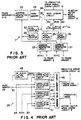
- the motion compensation predictor circuit 7 uses the motion vectors MVOI and MV4I as the reference for performing motion compensation predictive for the block B I for a required mode, and the prediction error signals are output to a predictive error signal coding circuit 10 via a switch 8. In addition the motion compensation predictor circuit 7 outputs data relating to the motion vector and the predictive mode to the predictive error signal coding circuit 10.
- the predictive error signal coding circuit 10 codes the data that is read from the input frame F 2 via the switch 8. and codes the predictive error signals output from the predictive compensation predictor circuit 7.
- a motion vector mode coding circuit 9 codes the motion vector and the predictive mode.
- a microprocessor 11 overlaps the output of the predictive error signal coding circuit 10 and the motion vector mode coding circuit 9. and outputs it to a demodulation system via a transmission system not indicated in the figure.
- the motion compensation predictor circuit 7 is configured as indicated in FIG. 3 for example.
- An address generating circuit 21 generates an address of block B 0 from an address of block B I input by an address generating circuit 23 and the motion vector MVOI for between frames F 0 and F I , reads the data of that address from frame memory 1, and stores it in a work memory 24.
- an address generating circuit 22 generates an address of block B 4 from the address of the block B I input from the address generating circuit 23 and the motion vector MV4I for between frames F 4 and F I , reads that address from the frame memory 2 and stores it in the work memory 25.
- the data of block B 0 that is written to the work memory 24 is input to the mode judgment circuit 28 and also supplied to an adder 27.
- the data of block B 4 that is written to a mode judgment circuit 28 is input to the mode judgment circuit 28 and also supplied to the adder 27.
- the adder 27 outputs the block B 04 by linear interpolation of blocks B 0 and B 4 , as shown by the following equation.
- B 04 (B 0 ⁇ B(4-I) + B 4 ⁇ B I )/4
- the data of this block B 04 is also output to the mode judging circuit 28.
- a pixel counter 30 the number of pixels is counted by a pixel counter 30.
- the address generating circuit 23 reads the address of block B I from one of the frame memories 3 through 5 and outputs it to a work memory 26.
- the data of block B I that is stored in the work memory 26 is supplied to the mode judging circuit 28.
- the mode judging circuit 28 is configured as shown in FIG. 4, for example.
- the data of the block B I that is stored in the work memory 26 is supplied to correlation calculation circuits 41 through 44, and to the direct current (DC) component calculation circuit 45.
- the DC component calculation circuit 45 averages the data of block B I , generates a block B DC and outputs it to the correlation calculation circuit 44.
- the data of blocks B 0 , B 4 and B 04 are input to correlation calculation circuits 41 through 43.
- the correlation calculation circuit 41 calculates the correlation between blocks B 0 and B I and the mean square error (MSE0) between the two and outputs them.
- the correlation calculation circuit 42 calculates the correlation between blocks B 4 and B I and the mean square error (MSE4) between the two and outputs them
- the correlation calculation circuit 43 calculates the correlation between blocks B 04 and B I and the mean square error (MSE04) between the two and outputs them
- the correlation calculation circuit 44 calculates the correlation between blocks B DC and B I and the mean square error (MSEDC) between the two and outputs them.
- the respective coefficient values SEL0, SEL4, SEL04 and SELDC are determined as follows.
- a minimum value judgment circuit 46 judges the smallest value from the four correlation values, and makes the corresponding mode the predication mode. Then, that predictive mode and the motion vector in that predictive mode is output to the motion vector coding circuit 9 and a predictive error signal corresponding to the difference between the block B I and a constant value and the blocks B 0 , B 4 , B 04 predicted in the predictive mode is generated and output to the predictive error signal coding circuit 10.
- Block B 0 is the predictive block and the motion vector MV0I is coded.
- Block B 4 is the predictive block and the motion vector MV4I is coded.
- Block B 04 is the predictive block and the motion vectors MV0I and MV4I are coded.
- Block B DC is the predictive block and the motion vector is not coded.
- an object of the present invention is to provide a motion image data compression system that can perform accurate and efficient motion compensation with respect to minute movement by reducing the amount of coding and without producing image deterioration by the generation of a predictive block using the predicted motion vector.
- the present invention provides motion image data compression apparatus comprising:
- the invention enables the prediction of movements of one pixel or less, and therefore reduces the amount of coding.
- the predictive motion vector it is possible to use the predictive motion vector to generate a predictive block and therefore reduce the number of motion vectors for coding and therefore reduce the amount of coding.
- the block B ON is determined from the linear sum of block B O and B N and the block out of blocks B O , B N ,B ON ,B ON ' and B DC that has the greatest correlation with block B I is selected.
- the block B ON is further determined from the linear sum of the block B O and B N and so there is no deterioration of the image quality, and the amount of coding can be further reduced.
- the basic configuration of the motion image data compression system according to a first embodiment of the present invention is the same as that indicated for the conventional technology in FIG. 1.
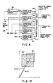
- the motion compensation predictor circuit 7 of FIG. 1 has the configuration as shown in FIG. 5, for example.
- the configuration of the address generating circuit 21 through to the pixel counter 30 is practically the same as that shown in FIG. 3 and so the description thereof is omitted.
- the motion vector MV04 from the motion vector detection circuit 6 and the number of frames I from a frame counter 52 are respectively input to a vector division circuit 51.
- the vector division circuit 51 generates predictive motion vectors MV0I' and MV4I' and respectively inputs them to address generating circuits 53 and 54.
- the address generation circuits 53 and 54 read the data of the addresses corresponding to the predictive motion vectors MV0I' and MV4I' and respectively store them in work memories 55 and 56.
- the data of the work memories 55 and 56 are respectively supplied to interpolation circuits 57 and 58 where the vector division circuit 51 multiplies them by a coefficient corresponding to the output signal k, and outputs the result to an adder 59.
- the output of the adder 59 is output to the mode judging circuit 28.
- the mode judging circuit 28 is configured as shown in FIG. 6. More specifically, in the configuration shown in FIG. 4, there is a correlation calculation circuit 61 added and the block B 04' and block B I are input to the correlation calculation circuit 61. Then, the minimum value judgment circuit 46 is configured so as to judge the minimum value of the output of the correlation calculation circuit 61 and the correlation calculation circuit 41 through 44. The other portions of the configuration are the same as those in the configuration shown in FIG. 4.
- the first means is configured from the address generating circuit 21 and the work memory 24, the second means is configured from the address generation circuits 2 and the work memory 25, the third means is configured from the address generation circuits 53 and 54, the work memories 55 and 56, the interpolation circuits 57 and 58 and the adder 59, the fourth means is configured from the DC calculation circuit 45, the fifth means is configured from the minimum value judging circuit 46 and the sixth means is generated from the adder 27.
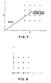
- these predictive motion vectors have a resolution of 1/4 of a pixel.
- the address generating circuit 54 reads for the 16 pixel data P ij of the periphery of the interpolation position indicated by the predictive motion vector MV4I' and writes to the work memory 56.
- the predictive motion vector has a resolution of 1/4 of a pixel
- the interpolation circuits 57 and 58 store coefficients F kij corresponding to the signals k and perform the following calculations with the 16 pixel data Pij described above.
- P ⁇ P ij ⁇ F kij
- the interpolation circuit 57 uses this value P to generate the predictive block B 0' .
- the interpolation circuit 58 uses this value P to generate the predictive block B 4' .
- the adder 59 multiplies the data of the block B 0' inserted from the interpolation circuit 57 by the coefficient (1 - ⁇ ), and multiplies the data of the block B 4' input from the interpolation circuit 58 by the coefficient ⁇ , and adds the two together.
- the adder 59 outputs the block B 04' by the linear interpolation of blocks B 0' and B 4' in the same manner as the adder 27 and as shown by the following equation.
- B 04' ⁇ B 0' ⁇ (4-I) + B 4' ⁇ I ⁇ /4
- This predictive block B 04' is input to the correlation calculation circuit 61 of the mode judgment circuit 28.
- the correlation calculation circuit 61 calculates the mean square error (MSE04') between the block B I and the predictive block B 04' and also calculates the correlation value SEL04' using the following equation.
- SEL04' MSE04' - ⁇
- ⁇ is a coefficient that satisfies the following condition. 0 ⁇ ⁇
- the minimum value judgment circuit 46 judges the minimum value of the five correlation values SEL0, SEL4, SEL04, SELDC and SEL04'. Then, when the correlation value SEL04' has been selected as the minimum value, the difference between the predictive block B 04' and the block B I is output to the predictive error signal coding circuit 10 as the signal of the predictive error block. In addition, the motion vector MV04 used in frames 1, 2 and 3 is output to the motion vector mode coding circuit 9.
- the predictive mode is mode 5 at this time
- the data for this mode 5 is also output to the motion vector mode coding circuit 9.
- the modes 1 through 4 described above also have mode 5 added to them.
- mode 5 there is one motion vector and so the amount of coding is less than for mode 3.
- the value of the coefficient ⁇ is set to a value that is large to a certain extent and the selection of mode 5 is made easier. Accordingly, it is possible for the mean amount of coding to be reduced.
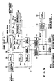
- the address generating circuits 53 and 54 and the work memories 55 and 56 of the first embodiment shown in FIG. 5 are omitted and the predictive motion vectors MV0I' and MV4I' output from the vector division circuit 51 are respectively supplied to the address generating circuits 21 and 22, and the corresponding data are written to the work memories 24 and 25.
- a vector division circuit 41 judges whether or not the predictive motion vector MV0I' exists in the vicinity of the motion vector MV0I and whether the predictive motion vector MV4I' exists in the vicinity of the motion vector MV4I.
- Numeral 42 shows a frame counter.
- the vector division circuit 41 stops the operation for the generation of the predictive block B 04' by interpolation circuits 47 and 48, and an adder 59. As a result, the selection of modes 1 through 4 is performed in the same manner as in the case of the conventional configuration.
- pixels of a range that includes both the block B 0 and the predictive block B 0' are read from the frame memory 1 and written to the work memory 24.
- pixels of a range that includes both the block B 4 and the predictive block B 4' are read from the frame memory 2 and written to the work memory 25.
- the coding system codes the mode and the codes modes are used to perform coding of the motion vectors MV0I, MV4I and MV04.
- the motion vector is used in the same manner as the coding system for each mode and the calculations are performed in the same manner to determine the predictive block.
- the sum of the coded predictive error block and the coded block is used to determine the coded block for each block unit.
- the predictive vector is used to calculate the data of the interpolation position but instead of performing these calculations, it is also possible to use data of pixels in the position closest to the interpolation position as it is. If this is done, then it is not possible to increase the resolution but the complex calculations are no longer necessary and so the configuration can be simplified.
- mode 3 it is possible to not use the mode 3 described above and for only modes 1, 2, 4 and 5 to be used. If this is done, then the image quality will deteriorate when compared to the case when mode 3 is used but there will be no cases when two motion vectors are coded and so the amount of coding can be reduced when compared to the case when mode 3 is used.
Landscapes
- Engineering & Computer Science (AREA)
- Multimedia (AREA)
- Signal Processing (AREA)
- Computer Vision & Pattern Recognition (AREA)
- Physics & Mathematics (AREA)
- General Physics & Mathematics (AREA)
- Theoretical Computer Science (AREA)
- Compression Or Coding Systems Of Tv Signals (AREA)
- Compression, Expansion, Code Conversion, And Decoders (AREA)
- Image Analysis (AREA)
- Color Television Systems (AREA)
Claims (11)
- Vorrichtung zur Kompression von Bewegungsbilddaten, enthaltend:eine erste Einrichtung (21, 24) zum Teilen eines Iten Rahmens, I = 1,2....N-1, zwischen zwei Rahmen F0 und FN von N Rahmen, wobei N eine ganze Zahl von 2 oder mehr ist, digitaler Bewegungsbilder in einen Block BI aus mehreren Pixeln zum Erzeugen des Bewegungsvektors MVOI vom Rahmen F0 und FI für jeden der geteilten Blöcke BI und zum Erzeugen des Blocks B0, der den Bewegungsvektor MVOI verwendet, um den Block BI vorauszusagen; und eine zweite Einrichtung (22, 25) zum Erzeugen eines Bewegungsvektors MVNI zwischen den Rahmen FN und FI für jeden Block BI und zum Erzeugen eines Blocks BN zum Voraussagen des Blocks BI auf der Grundlage des Bewegungsvektors MVNI;wobei die Blöcke B0 und BN gebildet sind aus Pixeldaten von Rahmen F0 bzw. FN;gekennzeichnet durch:eine dritte Einrichtung (53 - 59)1. zum Erzeugen von Bewegungsvektoren MVON oder MVNO vom Rahmen FN und F0 für jeden Block BI,2. zum Erzeugen eines prädiktiven Bewegungsvektors MVOI' zwischen den Rahmen F0 und FI unter Verwendung der Bewegungsvektoren MVON oder MVNO,3. zum Erzeugen eines Blocks B0' zum Voraussagen des Blocks BI unter Verwendung des Bewegungsvektors MVOI',4. zum Erzeugen eines prädiktiven Bewegungsvektors MVNI' zwischen den Rahmen FN und FI unter Verwendung der Bewegungsvektoren MVON oder MVNO,5. zum Erzeugen eines Blocks BN' zum Voraussgen des Blocks BI unter Verwendung des prädiktiven Bewegungsvektors MVNI', und6. zum Erzeugen eines Blocks BON', der die lineare Interpolation der Blöcke B0' und BN' darstellt,eine vierte Einrichtung (45) zum Erzeugen eines Blocks BDC aus dem Mittelwert des besagten Blocks BI undeine fünfte Einrichtung (46) zum Auswählen und Ausgeben eines Blocks, für den die Körrelation mit dem Block BI am größten ist.
- Vorrichtung zur Kompression von Bewegungsbilddaten nach Anspruch 1, ferner enthaltend:
eine sechste Einrichtung (27) zum Erzeugen eines Blocks B0N, der gebildet ist durch lineare Interpolation der Blöcke B0 und BN', wobei die fünfte Einrichtung denjenigen Block aus den Blöcken B0, BN, B0N, B0N' und BDC auswählt, für den die Korrelation mit dem Block BI am größten ist. - Vorrichtung zur Kompression von Bewegungsbilddaten nach Anspruch 1, bei der:
die vierte und fünfte Einrichtung eine Modusbeurteilungsschaltung (28) konfigurieren. - Vorrichtung zur Kompression von Bewegungsbilddaten nach Anspruch 3, bei der:die erste Einrichtung enthält eine erste Adreßsschaltung (21) zum Bestimmen des Blocks B0 als erstes Adreßdatum auf der Grundlage des Ausgangs eines ersten Rahmenspeichers und einer Bewegungsvektordetektionsschaltung, und einen ersten Arbeitsspeicher (24), der das erste von dieser Schaltung ausgegebene Adreßdatum speichert,die zweite Einrichtung enthält eine zweite Adreßschaltung (22) zum Bestimmen des Blocks BN als zweites Adreßdatum auf der Grundlage des Ausgangs eines zweiten Rahmenspeichers und der Bewegungsvektordetektionsschaltung, und einen zweiten Arbeitsspeicher (25), der das zweite von dieser Schaltung ausgegebene Adreßdatum speichert,die dritte Einrichtung enthält dritte und vierte Adreßerzeugungsschaltungen (53, 54), dritte und vierte Arbeitsspeicher (55, 56) zum Speichern der von diesen Schaltungen ausgebenenen dritten und vierten Adreßdaten, erste und zweite Interpolationsschaltungen (57, 58), die eine lineare Interpolationsberechnung vom Ausgang von diesen dritten und vierten Arbeitsspeichern vornehmen, und ein erstes Addierglied (59), das die Ausgänge der ersten und zweiten Interpolationsschaltungen addiert,die vierte Einrichtung enthält eine Gleichstrom- oder DC-Komponentenberechnungsschaltung (45), die für die Modusbeurteilungsschaltung (28) vorgesehen ist und die die DC-Komponenten-Berechnungen auf der Grundlage eines von einer fünften Adreßerzeugungsschaltung (23) ausgegebenen fünften Adreßdatums vornimmt,die fünfte Einrichtung enthält eine Minimumwertbeurteilungsschaltung (46), die einen Minimumwert auf der Grundlage eines Ausgangs der DC-Berechnungsschaltung (45) und von den ersten bis vierten Arbeitsspeichern (21, 22, 23, 53, 54) ausgegebenen Adreßdaten beurteilt, die für die Modusbeurteilungsschaltung (28) vorgesehen sind.
- Vorrichtung zur Kompression von Bewegungsbilddaten nach Anspruch 4, bei der:
die Modusbeurteilungsschaltung (28) mit einer ersten Korrelationsberechnungsschaltung (44) versehen ist, um eine Korrelation eines Ausgangs zu berechnen, der von der DC-Berechnungsschaltung (45) berechnet worden ist, und mit einer zweiten bis fünften Korrelationsschaltung (41, 42, 43) versehen ist, die Korrelationen der ersten von den ersten bis vierten Arbeitsspeichern (24, 25, 26, 55, 56) ausgegebenen ersten bis vierten Daten berechnen. - Vorrichtung zur Kompression von Bewegungsbilddaten nach Anspruch 4, ferner enthaltend.
eine sechste Einrichtung (27) zum Bestimmen eines Blocks B0N' der durch lineare Interpolation der Blöcke B0 und BN gebildet ist, wobei die fünfte Einrichtung (46) denjenigen Block aus den Blöcken B0, BN, B0N und BDC auswählt, für den die Korrelation mit dem Block BI am größten ist. - Vorrichtung zur Kompression von Bewegungsbilddaten nach Anspruch 6, bei der:
die sechste Einrichtung enthält ein zweites Addierglied (27), das den Block B0N dadurch bestimmt, daß die ersten und zweiten Adreßdatenausgänge zu der Modusbeurteilungsschaltung (28) von den ersten und zweiten Arbeitsspeichern (55, 56) addiert werden. - Vorrichtung zur Kompression von Bewegungsbilddaten nach Anspruch 4, ferner enthaltend:
eine dritte und vierte Adreßerzeugungsschaltung (21, 22), die die dritte und vierte Einrichtung konfiguriert, denen prädiktive Bewegungsvektorsignale zugeführt werden, und ferner versehen ist mit einer Vektorteilungsschaltung (51), die einen Interpolationskoeffizienten an die erste und zweite Interpolationsschaltung (57, 58) liefert. - Vorrichtung zur Kompression von Bewegungsbilddaten nach Anspruch 8, ferner enthaltend:
einen Rahmenzähler (52), der eine Anzahl Rahmen der Bewegungsbilddaten an die Vektorteilungsschaltung (51) liefert, wobei der Vektorteilungsschaltung (51) die besagte Anzahl Rahmen zugeführt wird und der Bewegungsvektordetektionsschaltung (9) ein detektierter Bewegungsvektor zugeführt wird. - Vorrichtung zur Kompression von Bewegungsbilddaten nach Anspruch 1, bei der:die erste Einrichtung enthält eine erste Adreßschaltung (21) zum Bestimmen des Block B0 als erstes Adreßdatum auf der Grundlage des Ausgangs eines erstens Rahmenspeichers (1) und einer Bewegungsvektordetektionsschaltung (6), und einen ersten Arbeitsspeicher (24), der das von dieser Schaltung ausgegebene erste Adreßdatum speichert,die zweite Einrichtung enthält eine zweite Adreßschaltung (22) zum Bestimmen des Blocks BN als zweites Adreßdatum auf der Grundlage des Ausgangs eines zweiten Rahmenspeichers (2) und der Bewegungsvektordetektionsschaltung (6), und einen zweiten Arbeitsspeicher (25), der das von dieser Schaltung ausgegebene zweite Adreßdatum speichert,die dritte Einrichtung enthält einen Rahmenzähler (42), der eine Anzahl Rahmen der Bewegungsbildsignale zählt, eine Vektorteilungsschaltung (41), die einen prädiktiven Bewegungsvektor auf der Grundlage des von diesem Zähler gezählten Wertes und eines von der Bewegungsvektordetektionsschaltung detektierten Bewegungsvektors (MV4I, MV0I und MV04) teilt, eine Interpolationsschaltung (47, 48), die die Interpolationsberechnung ausführt auf der Grundlage eines Ausgangs dieser Teilungsschaltung (41) und von einem der Ausgänge des ersten und zweiten Arbeitsspeichers (24, 25), und ein erstes Addierglied (49), das die Ausgänge der ersten und zweiten Interpolationsschaltung (47, 48) addiert,die vierte Einrichtung enthält eine Gleichstrom oder DC-Kompontentenberechnungsschaltung (45), die für die Modusbeurteilungsschaltung vorgesehen ist und die die DC-Komponentenberechnungen auf der Grundlage eines von einer fünften Adreßerzeugungsschaltung (23) ausgegebenen fünften Adreßdatums vornimmt, unddie fünfte Einrichtung enthält eine Miniumwertbeurteilungsschaltung (46), die einen Minimumwert auf der Grundlage eines Ausgangs der DC-Berechnungsschaltung (45) und von den ersten, zweiten und fünften Arbeitsspeichern ausgegebenen Adreßdaten vornimmt, die für die Modusbeurteilungsschaltung (28) vorgesehen sind.
- Vorrichtung zur Kompression von Bewegungsbilddaten nach Anspruch 10, ferner enthaltend:
eine sechste Einrichtung (27), die den Block B0N bestimmt, der durch lineare Interpolation der Blöcke B0 und BN gebildet worden ist, wobei die fünfte Einrichtung denjenigen Block aus den Blöcken B0, BN, B0N, B0N' und BDC auswählt, für den die Korrelation mit dem Block BI am größten ist.
Applications Claiming Priority (2)
| Application Number | Priority Date | Filing Date | Title |
|---|---|---|---|
| JP2050270A JPH03252287A (ja) | 1990-02-28 | 1990-02-28 | 動画像圧縮装置 |
| JP50270/90 | 1990-02-28 |
Publications (3)
| Publication Number | Publication Date |
|---|---|
| EP0447068A2 EP0447068A2 (de) | 1991-09-18 |
| EP0447068A3 EP0447068A3 (en) | 1993-02-24 |
| EP0447068B1 true EP0447068B1 (de) | 1997-07-16 |
Family
ID=12854263
Family Applications (1)
| Application Number | Title | Priority Date | Filing Date |
|---|---|---|---|
| EP91301629A Expired - Lifetime EP0447068B1 (de) | 1990-02-28 | 1991-02-28 | Kompressionssystem von bewegten Bilddaten |
Country Status (4)
| Country | Link |
|---|---|
| US (1) | US5157742A (de) |
| EP (1) | EP0447068B1 (de) |
| JP (1) | JPH03252287A (de) |
| DE (1) | DE69126804T2 (de) |
Families Citing this family (43)
| Publication number | Priority date | Publication date | Assignee | Title |
|---|---|---|---|---|
| US5732164A (en) * | 1991-05-23 | 1998-03-24 | Fujitsu Limited | Parallel video processor apparatus |
| JP3227173B2 (ja) * | 1991-06-24 | 2001-11-12 | キヤノン株式会社 | 撮像装置及びその方法 |
| EP0520765B1 (de) * | 1991-06-25 | 1999-05-12 | Canon Kabushiki Kaisha | Verfahren und Vorrichtung zur Detektion eines Bewegungsvektors sowie Kodierungsverfahren und Vorrichtung zur Anwendung eines solchen Verfahrens und Vorrichtung |
| EP0533195A2 (de) * | 1991-09-20 | 1993-03-24 | Sony Corporation | Vorrichtung zum Kodieren und/oder Dekodieren von Bildsignalen |
| JP2586260B2 (ja) * | 1991-10-22 | 1997-02-26 | 三菱電機株式会社 | 適応的ブロッキング画像符号化装置 |
| JP2611591B2 (ja) * | 1991-10-31 | 1997-05-21 | 日本ビクター株式会社 | 動き補償装置 |
| US5414469A (en) * | 1991-10-31 | 1995-05-09 | International Business Machines Corporation | Motion video compression system with multiresolution features |
| US5369449A (en) * | 1991-11-08 | 1994-11-29 | Matsushita Electric Industrial Co., Ltd. | Method for predicting move compensation |
| JP2962012B2 (ja) * | 1991-11-08 | 1999-10-12 | 日本ビクター株式会社 | 動画像符号化装置及びその復号装置 |
| USRE39276E1 (en) * | 1991-11-08 | 2006-09-12 | Matsushita Electric Industrial Co., Ltd. | Method for determining motion compensation |
| USRE39279E1 (en) * | 1991-11-08 | 2006-09-12 | Matsushita Electric Industrial Co., Ltd. | Method for determining motion compensation |
| GB2267590B (en) * | 1992-05-29 | 1996-03-27 | Gold Star Co | Memory access delay control circuit for image motion compensation |
| JPH05336514A (ja) * | 1992-05-29 | 1993-12-17 | Sony Corp | 画像符号化装置 |
| US5461423A (en) * | 1992-05-29 | 1995-10-24 | Sony Corporation | Apparatus for generating a motion vector with half-pixel precision for use in compressing a digital motion picture signal |
| JP3443867B2 (ja) * | 1992-06-26 | 2003-09-08 | ソニー株式会社 | 画像信号符号化、復号化方法及び画像信号記録媒体 |
| JP3308990B2 (ja) * | 1992-07-03 | 2002-07-29 | 松下電器産業株式会社 | 動画像の予測符号化方法及び予測符号化装置 |
| KR950005621B1 (ko) * | 1992-09-30 | 1995-05-27 | 주식회사금성사 | 영상 디코더 |
| KR950006769B1 (ko) * | 1992-12-31 | 1995-06-22 | 현대전자산업주식회사 | 고선명 텔레비젼의 색차신호 동벡터 추출방법 및 움직임 보상장치 |
| US5398079A (en) * | 1993-01-27 | 1995-03-14 | General Instrument Corporation | Half-pixel interpolation for a motion compensated digital video system |
| JP2636674B2 (ja) * | 1993-05-25 | 1997-07-30 | 日本電気株式会社 | 動画像の動きベクトル検出装置 |
| US5598514A (en) * | 1993-08-09 | 1997-01-28 | C-Cube Microsystems | Structure and method for a multistandard video encoder/decoder |
| JP3031152B2 (ja) * | 1993-12-24 | 2000-04-10 | 日本電気株式会社 | 動き予測プロセッサ及び動き予測装置 |
| JP3149303B2 (ja) * | 1993-12-29 | 2001-03-26 | 松下電器産業株式会社 | デジタル画像符号化方法及びデジタル画像復号化方法 |
| CA2139794C (en) * | 1994-01-18 | 2006-11-07 | Robert John Gove | Frame pixel data generation |
| US5592226A (en) * | 1994-01-26 | 1997-01-07 | Btg Usa Inc. | Method and apparatus for video data compression using temporally adaptive motion interpolation |
| EP0719049B1 (de) * | 1994-12-20 | 2003-05-28 | Matsushita Electric Industries Co., Ltd. | Verfahren und Vorrichtung zur Bildkodierung |
| AU5027796A (en) | 1995-03-07 | 1996-09-23 | Interval Research Corporation | System and method for selective recording of information |
| US5910909A (en) * | 1995-08-28 | 1999-06-08 | C-Cube Microsystems, Inc. | Non-linear digital filters for interlaced video signals and method thereof |
| WO1997010564A1 (en) | 1995-09-15 | 1997-03-20 | Interval Research Corporation | A method of compressing a plurality of video images |
| KR0163922B1 (ko) * | 1995-09-19 | 1999-01-15 | 김광호 | 카메라 영상의 움직임 벡터 검출장치 및 그 검출방법 |
| US5987181A (en) * | 1995-10-12 | 1999-11-16 | Sharp Kabushiki Kaisha | Coding and decoding apparatus which transmits and receives tool information for constructing decoding scheme |
| US6263507B1 (en) | 1996-12-05 | 2001-07-17 | Interval Research Corporation | Browser for use in navigating a body of information, with particular application to browsing information represented by audiovisual data |
| US5893062A (en) | 1996-12-05 | 1999-04-06 | Interval Research Corporation | Variable rate video playback with synchronized audio |
| JPH118856A (ja) * | 1997-06-17 | 1999-01-12 | Mitsubishi Electric Corp | 画像符号化方法及びその装置 |
| US6018368A (en) * | 1997-07-11 | 2000-01-25 | Samsung Electro-Mechanics Co., Ltd. | Scalable encoding apparatus and method with improved function of scaling motion vector |
| EP0944245B1 (de) * | 1998-03-20 | 2001-07-25 | SGS-THOMSON MICROELECTRONICS S.r.l. | Hierarchischer rekursiver Bewegungsschätzer für Bewegtbildkodierer |
| JP3688489B2 (ja) * | 1998-12-25 | 2005-08-31 | 株式会社東芝 | 画像認識方法および画像認識装置 |
| US7155735B1 (en) | 1999-10-08 | 2006-12-26 | Vulcan Patents Llc | System and method for the broadcast dissemination of time-ordered data |
| US6757682B1 (en) | 2000-01-28 | 2004-06-29 | Interval Research Corporation | Alerting users to items of current interest |
| US7830565B2 (en) * | 2006-06-27 | 2010-11-09 | Motorola, Inc. | Image capture device with rolling band shutter |
| US8213511B2 (en) * | 2007-04-30 | 2012-07-03 | Texas Instruments Incorporated | Video encoder software architecture for VLIW cores incorporating inter prediction and intra prediction |
| US8223235B2 (en) * | 2007-12-13 | 2012-07-17 | Motorola Mobility, Inc. | Digital imager with dual rolling shutters |
| US8379727B2 (en) * | 2008-09-26 | 2013-02-19 | General Instrument Corporation | Method and apparatus for scalable motion estimation |
Family Cites Families (12)
| Publication number | Priority date | Publication date | Assignee | Title |
|---|---|---|---|---|
| US4383272A (en) * | 1981-04-13 | 1983-05-10 | Bell Telephone Laboratories, Incorporated | Video signal interpolation using motion estimation |
| JPS58127488A (ja) * | 1982-01-25 | 1983-07-29 | Kokusai Denshin Denwa Co Ltd <Kdd> | テレビジヨン信号の適応予測符号化方式 |
| JPS60168276A (ja) * | 1984-02-13 | 1985-08-31 | Kokusai Denshin Denwa Co Ltd <Kdd> | 画面上の移動体の動き方向検出方式 |
| US4727422A (en) * | 1985-06-03 | 1988-02-23 | Picturetel Corporation | Method and apparatus for efficiently communicating image sequence having improved motion compensation |
| US4661849A (en) * | 1985-06-03 | 1987-04-28 | Pictel Corporation | Method and apparatus for providing motion estimation signals for communicating image sequences |
| JP2506332B2 (ja) * | 1986-03-04 | 1996-06-12 | 国際電信電話株式会社 | 動画像信号の高能率符号化方式 |
| JP2540809B2 (ja) * | 1986-07-30 | 1996-10-09 | ソニー株式会社 | 高能率符号化装置 |
| GB2195216B (en) * | 1986-09-01 | 1990-11-21 | British Broadcasting Corp | Video transmission system |
| EP0294962B1 (de) * | 1987-06-09 | 1995-07-19 | Sony Corporation | Bewertung von Bewegungsvektoren in Fernsehbildern |
| FR2623955B1 (fr) * | 1987-11-27 | 1990-04-27 | Labo Electronique Physique | Procede et dispositif d'estimation et de compensation de mouvement dans une sequence d'images et leur application dans un systeme de transmission d'images de television a haute definition |
| US5010401A (en) * | 1988-08-11 | 1991-04-23 | Mitsubishi Denki Kabushiki Kaisha | Picture coding and decoding apparatus using vector quantization |
| GB2231226B (en) * | 1989-04-27 | 1993-09-22 | Sony Corp | Motion dependent video signal processing |
-
1990
- 1990-02-28 JP JP2050270A patent/JPH03252287A/ja active Pending
-
1991
- 1991-02-27 US US07/661,861 patent/US5157742A/en not_active Expired - Lifetime
- 1991-02-28 DE DE69126804T patent/DE69126804T2/de not_active Expired - Fee Related
- 1991-02-28 EP EP91301629A patent/EP0447068B1/de not_active Expired - Lifetime
Also Published As
| Publication number | Publication date |
|---|---|
| JPH03252287A (ja) | 1991-11-11 |
| DE69126804D1 (de) | 1997-08-21 |
| EP0447068A3 (en) | 1993-02-24 |
| EP0447068A2 (de) | 1991-09-18 |
| US5157742A (en) | 1992-10-20 |
| DE69126804T2 (de) | 1997-11-20 |
Similar Documents
| Publication | Publication Date | Title |
|---|---|---|
| EP0447068B1 (de) | Kompressionssystem von bewegten Bilddaten | |
| US4727422A (en) | Method and apparatus for efficiently communicating image sequence having improved motion compensation | |
| US6008852A (en) | Video coder with global motion compensation | |
| EP0484140B1 (de) | Verfahren zur Kompression von bewegten Bildsignalen nach dem Zeilensprungverfahren | |
| EP1912172B1 (de) | Interpolationsverfahren für ein bewegungskompensiertes Bild und Vorrichtung zur Umsetzung dieses Verfahrens | |
| KR100638500B1 (ko) | 정보 신호 처리 장치, 화상 정보 변환 장치, 및 화상 디스플레이 장치 | |
| US5621481A (en) | Motion vector detecting apparatus for determining interframe, predictive error as a function of interfield predictive errors | |
| JP3031152B2 (ja) | 動き予測プロセッサ及び動き予測装置 | |
| KR100416444B1 (ko) | 모션벡터선택방법및이방법을수행하는이미지처리장치 | |
| EP0661887A2 (de) | Bewegtbildkodierer | |
| US20020001347A1 (en) | Apparatus and method for converting to progressive scanning format | |
| JP4147632B2 (ja) | 画像情報変換装置、画像情報変換方法、およびテレビジョン受像機 | |
| JP3946781B2 (ja) | 画像情報変換装置及び方法 | |
| EP0547460B1 (de) | Verfahren und System zum Anpassen des Auffrischungszyklus an die Komplexität des Bildes | |
| JP3362463B2 (ja) | フレーム補間装置 | |
| US5706055A (en) | Motion compensated predictive picture production apparatus | |
| JP4300603B2 (ja) | 画像情報変換装置および方法 | |
| JP3723995B2 (ja) | 画像情報変換装置および方法 | |
| JP4140091B2 (ja) | 画像情報変換装置および画像情報変換方法 | |
| JP3121519B2 (ja) | 動きベクトルを用いた動き内挿方法および動き内挿回路ならびに動きベクトル検出方法および動きベクトル検出回路 | |
| JP3653287B2 (ja) | 画像情報変換装置及び画像情報変換方法 | |
| KR100213287B1 (ko) | 영상복호기의 에러보상장치 | |
| JP3826434B2 (ja) | 信号変換装置および方法 | |
| JP2000083224A (ja) | 画像情報変換装置 | |
| KR100275546B1 (ko) | 적응형 변환 파라미터 검출방법 |
Legal Events
| Date | Code | Title | Description |
|---|---|---|---|
| PUAI | Public reference made under article 153(3) epc to a published international application that has entered the european phase |
Free format text: ORIGINAL CODE: 0009012 |
|
| AK | Designated contracting states |
Kind code of ref document: A2 Designated state(s): DE FR GB |
|
| PUAL | Search report despatched |
Free format text: ORIGINAL CODE: 0009013 |
|
| AK | Designated contracting states |
Kind code of ref document: A3 Designated state(s): DE FR GB |
|
| 17P | Request for examination filed |
Effective date: 19930316 |
|
| 17Q | First examination report despatched |
Effective date: 19950623 |
|
| GRAG | Despatch of communication of intention to grant |
Free format text: ORIGINAL CODE: EPIDOS AGRA |
|
| GRAH | Despatch of communication of intention to grant a patent |
Free format text: ORIGINAL CODE: EPIDOS IGRA |
|
| GRAH | Despatch of communication of intention to grant a patent |
Free format text: ORIGINAL CODE: EPIDOS IGRA |
|
| GRAA | (expected) grant |
Free format text: ORIGINAL CODE: 0009210 |
|
| AK | Designated contracting states |
Kind code of ref document: B1 Designated state(s): DE FR GB |
|
| REF | Corresponds to: |
Ref document number: 69126804 Country of ref document: DE Date of ref document: 19970821 |
|
| ET | Fr: translation filed | ||
| PLBE | No opposition filed within time limit |
Free format text: ORIGINAL CODE: 0009261 |
|
| STAA | Information on the status of an ep patent application or granted ep patent |
Free format text: STATUS: NO OPPOSITION FILED WITHIN TIME LIMIT |
|
| 26N | No opposition filed | ||
| REG | Reference to a national code |
Ref country code: GB Ref legal event code: IF02 |
|
| PGFP | Annual fee paid to national office [announced via postgrant information from national office to epo] |
Ref country code: DE Payment date: 20090226 Year of fee payment: 19 |
|
| PGFP | Annual fee paid to national office [announced via postgrant information from national office to epo] |
Ref country code: GB Payment date: 20090225 Year of fee payment: 19 |
|
| PGFP | Annual fee paid to national office [announced via postgrant information from national office to epo] |
Ref country code: FR Payment date: 20090213 Year of fee payment: 19 |
|
| GBPC | Gb: european patent ceased through non-payment of renewal fee |
Effective date: 20100228 |
|
| REG | Reference to a national code |
Ref country code: FR Ref legal event code: ST Effective date: 20101029 |
|
| PG25 | Lapsed in a contracting state [announced via postgrant information from national office to epo] |
Ref country code: FR Free format text: LAPSE BECAUSE OF NON-PAYMENT OF DUE FEES Effective date: 20100301 |
|
| PG25 | Lapsed in a contracting state [announced via postgrant information from national office to epo] |
Ref country code: DE Free format text: LAPSE BECAUSE OF NON-PAYMENT OF DUE FEES Effective date: 20100901 |
|
| PG25 | Lapsed in a contracting state [announced via postgrant information from national office to epo] |
Ref country code: GB Free format text: LAPSE BECAUSE OF NON-PAYMENT OF DUE FEES Effective date: 20100228 |