EP0447088B1 - Dispositif et procédé pour faire couler du métal fondu - Google Patents
Dispositif et procédé pour faire couler du métal fondu Download PDFInfo
- Publication number
- EP0447088B1 EP0447088B1 EP19910301774 EP91301774A EP0447088B1 EP 0447088 B1 EP0447088 B1 EP 0447088B1 EP 19910301774 EP19910301774 EP 19910301774 EP 91301774 A EP91301774 A EP 91301774A EP 0447088 B1 EP0447088 B1 EP 0447088B1
- Authority
- EP
- European Patent Office
- Prior art keywords
- slab
- insulating
- molten metal
- thickened
- tundish
- Prior art date
- Legal status (The legal status is an assumption and is not a legal conclusion. Google has not performed a legal analysis and makes no representation as to the accuracy of the status listed.)
- Expired - Lifetime
Links
- 229910052751 metal Inorganic materials 0.000 title claims description 39
- 239000002184 metal Substances 0.000 title claims description 39
- 239000000843 powder Substances 0.000 claims description 9
- VYPSYNLAJGMNEJ-UHFFFAOYSA-N Silicium dioxide Chemical compound O=[Si]=O VYPSYNLAJGMNEJ-UHFFFAOYSA-N 0.000 claims description 6
- 230000004907 flux Effects 0.000 claims description 5
- 239000011810 insulating material Substances 0.000 claims description 5
- 239000000463 material Substances 0.000 claims description 5
- OKTJSMMVPCPJKN-UHFFFAOYSA-N Carbon Chemical compound [C] OKTJSMMVPCPJKN-UHFFFAOYSA-N 0.000 claims description 4
- CPLXHLVBOLITMK-UHFFFAOYSA-N Magnesium oxide Chemical compound [Mg]=O CPLXHLVBOLITMK-UHFFFAOYSA-N 0.000 claims description 4
- 239000011230 binding agent Substances 0.000 claims description 4
- 239000000945 filler Substances 0.000 claims description 4
- 238000000227 grinding Methods 0.000 claims description 4
- PNEYBMLMFCGWSK-UHFFFAOYSA-N aluminium oxide Inorganic materials [O-2].[O-2].[O-2].[Al+3].[Al+3] PNEYBMLMFCGWSK-UHFFFAOYSA-N 0.000 claims description 3
- 238000000034 method Methods 0.000 claims description 3
- KXGFMDJXCMQABM-UHFFFAOYSA-N 2-methoxy-6-methylphenol Chemical compound [CH]OC1=CC=CC([CH])=C1O KXGFMDJXCMQABM-UHFFFAOYSA-N 0.000 claims description 2
- 239000004115 Sodium Silicate Substances 0.000 claims description 2
- 229920002472 Starch Polymers 0.000 claims description 2
- 229920001807 Urea-formaldehyde Polymers 0.000 claims description 2
- GZCGUPFRVQAUEE-SLPGGIOYSA-N aldehydo-D-glucose Chemical compound OC[C@@H](O)[C@@H](O)[C@H](O)[C@@H](O)C=O GZCGUPFRVQAUEE-SLPGGIOYSA-N 0.000 claims description 2
- 229910000323 aluminium silicate Inorganic materials 0.000 claims description 2
- 239000000404 calcium aluminium silicate Substances 0.000 claims description 2
- 235000012215 calcium aluminium silicate Nutrition 0.000 claims description 2
- 229940078583 calcium aluminosilicate Drugs 0.000 claims description 2
- WUKWITHWXAAZEY-UHFFFAOYSA-L calcium difluoride Chemical compound [F-].[F-].[Ca+2] WUKWITHWXAAZEY-UHFFFAOYSA-L 0.000 claims description 2
- 229910001634 calcium fluoride Inorganic materials 0.000 claims description 2
- 239000000378 calcium silicate Substances 0.000 claims description 2
- 229910052918 calcium silicate Inorganic materials 0.000 claims description 2
- OYACROKNLOSFPA-UHFFFAOYSA-N calcium;dioxido(oxo)silane Chemical compound [Ca+2].[O-][Si]([O-])=O OYACROKNLOSFPA-UHFFFAOYSA-N 0.000 claims description 2
- 229910052799 carbon Inorganic materials 0.000 claims description 2
- 239000008119 colloidal silica Substances 0.000 claims description 2
- HNPSIPDUKPIQMN-UHFFFAOYSA-N dioxosilane;oxo(oxoalumanyloxy)alumane Chemical compound O=[Si]=O.O=[Al]O[Al]=O HNPSIPDUKPIQMN-UHFFFAOYSA-N 0.000 claims description 2
- 239000000835 fiber Substances 0.000 claims description 2
- 239000010439 graphite Substances 0.000 claims description 2
- 229910002804 graphite Inorganic materials 0.000 claims description 2
- 239000000395 magnesium oxide Substances 0.000 claims description 2
- 229910044991 metal oxide Inorganic materials 0.000 claims description 2
- 239000010451 perlite Substances 0.000 claims description 2
- 235000019362 perlite Nutrition 0.000 claims description 2
- 229920001568 phenolic resin Polymers 0.000 claims description 2
- 230000000630 rising effect Effects 0.000 claims description 2
- 239000000377 silicon dioxide Substances 0.000 claims description 2
- NTHWMYGWWRZVTN-UHFFFAOYSA-N sodium silicate Chemical compound [Na+].[Na+].[O-][Si]([O-])=O NTHWMYGWWRZVTN-UHFFFAOYSA-N 0.000 claims description 2
- 229910052911 sodium silicate Inorganic materials 0.000 claims description 2
- 239000008279 sol Substances 0.000 claims description 2
- 239000008107 starch Substances 0.000 claims description 2
- 235000019698 starch Nutrition 0.000 claims description 2
- 239000010455 vermiculite Substances 0.000 claims description 2
- 235000019354 vermiculite Nutrition 0.000 claims description 2
- 229910052902 vermiculite Inorganic materials 0.000 claims description 2
- BPQQTUXANYXVAA-UHFFFAOYSA-N Orthosilicate Chemical compound [O-][Si]([O-])([O-])[O-] BPQQTUXANYXVAA-UHFFFAOYSA-N 0.000 claims 1
- 229910000831 Steel Inorganic materials 0.000 description 6
- 239000010959 steel Substances 0.000 description 6
- 239000000203 mixture Substances 0.000 description 4
- 239000000654 additive Substances 0.000 description 2
- 238000009413 insulation Methods 0.000 description 2
- OYPRJOBELJOOCE-UHFFFAOYSA-N Calcium Chemical compound [Ca] OYPRJOBELJOOCE-UHFFFAOYSA-N 0.000 description 1
- FYYHWMGAXLPEAU-UHFFFAOYSA-N Magnesium Chemical compound [Mg] FYYHWMGAXLPEAU-UHFFFAOYSA-N 0.000 description 1
- 240000007594 Oryza sativa Species 0.000 description 1
- 235000007164 Oryza sativa Nutrition 0.000 description 1
- 239000004411 aluminium Substances 0.000 description 1
- 229910052782 aluminium Inorganic materials 0.000 description 1
- XAGFODPZIPBFFR-UHFFFAOYSA-N aluminium Chemical compound [Al] XAGFODPZIPBFFR-UHFFFAOYSA-N 0.000 description 1
- 229910052791 calcium Inorganic materials 0.000 description 1
- 239000011575 calcium Substances 0.000 description 1
- 238000009749 continuous casting Methods 0.000 description 1
- 239000000428 dust Substances 0.000 description 1
- 230000003628 erosive effect Effects 0.000 description 1
- 239000010903 husk Substances 0.000 description 1
- 229910052749 magnesium Inorganic materials 0.000 description 1
- 239000011777 magnesium Substances 0.000 description 1
- 239000012254 powdered material Substances 0.000 description 1
- 230000000717 retained effect Effects 0.000 description 1
- 235000009566 rice Nutrition 0.000 description 1
- 150000004760 silicates Chemical class 0.000 description 1
Images

Classifications
-
- B—PERFORMING OPERATIONS; TRANSPORTING
- B22—CASTING; POWDER METALLURGY
- B22D—CASTING OF METALS; CASTING OF OTHER SUBSTANCES BY THE SAME PROCESSES OR DEVICES
- B22D11/00—Continuous casting of metals, i.e. casting in indefinite lengths
- B22D11/10—Supplying or treating molten metal
Definitions
- the invention relates to an insulating slab for use as a covering layer for molten metal in a molten metal handling vessel, according to the preamble of claim 1 and to a method of insulating the surface of molten metal in a handling vessel, according to the preamble of claim 14.
- pouring of molten metal from a ladle to another vessel, e.g. a mould is via an intermediate vessel, e.g. a tundish, particularly in the continuous casting of molten metal such as steel.
- a covering layer to the molten metal in a vessel such as a tundish in order to provide insulation against excessive heat loss and also to react with the molten metal to remove unwanted inclusions, e.g. of alumina.
- a vessel such as a tundish
- rice husks are frequently used or other, for example, basic materials formulated for the particularly desired reaction.
- Such covering layers have usually been applied in powder form but there have been proposals to apply a covering layer in sheet form. In principle this can be advantageous in reducing dust levels and in containing dangerous splashing of molten metal during the pouring operation.
- the use of two refractory heat-insulating slabs is described in British Patent Specification No. 1571333.
- the slabs are pivotally-mounted at an upper edge or in a wall portion of a tundish in spaced apart relationship and extending downward into the vessel.
- the molten metal is poured between the slabs which can, therefore, contain any splash and, as pouring continues, the slabs rise on the molten metal until they are horizontal.
- the slabs thereby provide a cover to reduce heat loss and to contain any powder additives.
- Tundishes which may be generally rectangular in plan form, usually are frusto-conical in vertical transverse section with the walls sloping outwardly in the upwards direction.
- One serious disadvantage of covering the molten metal by sheet material therefore, is that the sheet cannot cover the entire metal surface as the metal level rises and an increasing gap between sheet and tundish wall is unprotected.
- the present invention provides an insulating slab for use as a covering layer for the molten metal in a molten metal handling vessel having outwardly sloping side walls, e.g. a tundish, in which the slab is floatable on the molten metal surface and comprises at least a layer of heat-insulating material which is shaped to have thickened portions extending along at least two opposite edges, which thickened portions are capable of expansion and powdering under the action of the molten metal.
- the invention provides a method of insulating the surface of molten metal in a handling vessel having outwardly sloping side walls, e.g. a tundish, which comprises placing a covering layer in the form of a floatable slab of heat-insulating material on the surface of the molten metal, in which the slab is shaped to have thickened portions extending along at least two opposite edges of the slab, which thickened portions of the insulating material layer extend along the two sides of the slab that correspond to the outwardly sloping walls of the handling vessel.
- the gap that would otherwise appear between slab and sidewall can be substantially filled with powdered material that has been formed by expansion and erosion of the thickened portions under the action of the hot metal.
- composition of the insulating layer of the slab can be particularly formulated to expand and powder under the action of the heat of the molten metal.
- the insulating layer may be formed from refractory fibres, e.g. calcium silicate or aluminosilicate; refractory filler, e.g. silica, alumina, magnesia or refractory silicates; and a binder, e.g. colloidal silica sol, sodium silicate, starch, phenol-formaldehyde resin or urea-formaldehyde resin.
- Expandable materials e.g. expandable graphite, perlite or vermiculite may conveniently be included in order to give the desired expansion and powdering properties.
- a second layer which can be a reactive flux layer of lesser insulating properties than the insulating layer, is attached to the underside of the insulating layer so that the slab can be chosen to optimise the insulation and reaction properties that are desired.
- the second layer may be formed from any desired flux composition.
- Such compositions are well known and may be based on various metallic oxides, e.g. mixtures of oxides of calcium, aluminium and magnesium, with other additives, e.g. carbon and calcium fluoride.
- the thickened edge portions of the slab extend downwardly from the plane of the slab when considered in its horizontal position in a tundish.
- two or more covering slabs of the invention in a tundish.
- two slabs may be positioned in the empty tundish, one to each side of the entry zone.
- a flat conventional slab 1 is made of fibre, filler and binder. In contact with molten steel the slab will expand and form powder, the powder and any residual slab forming a layer on top of the rising level of molten metal.
- slab 2 has a thickened, depending edge 3. This edge is of frusto-conical or wedge shape. It too will expand and form powder under the action of contact with molten steel.
- Figure 3 shows a slab 4 having a thickened depending edge 5 of different, parallelopiped shape.
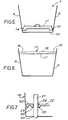
- Figure 4 shows the insulating slab 2 of Figure 2 with a reactive flux layer 6 attached to its underside.
- a tundish 7 has upwardly and outwardly sloping sidewalls 8 and 9 and a base 10.
- a slab 11 of the invention is placed in the tundish when empty and rests with its depending thickened edges 13 and 14 contacting the side walls 8 and 9 near to base 10.
- Molten steel is then introduced into the tundish. It enters underneath slab 11, which then rises floating on the molten metal surface.
- the filled tundish is shown in Figure 6.
- the hot metal causes expansion and powdering of the slab.
- the edges 13 and 14 have powdered to cover the gaps 15 and 16 that would otherwise have been left uncovered between the sidewalls and the slab.
- the underside layer 17 of the slab has also started to react with the metal and, as shown, has to a degree insulated the upper layer 18 of the slab from the metal so that the slab has still retained some of its integrity.
- tundish 19 has an outlet 20, closable by a stopper rod 21.
- a slab 22 of the invention has a thickened edge 23 and an aperture 24 to accommodate the stopper rod.
- the aperture 24 is also surrounded by a depending thickened portion 25 of the slab.
Landscapes
- Engineering & Computer Science (AREA)
- Mechanical Engineering (AREA)
- Continuous Casting (AREA)
- Casting Support Devices, Ladles, And Melt Control Thereby (AREA)
Claims (14)
- Plaque calorifuge pour l'emploi en tant que couche de recouvrement du métal en fusion dans une cuve de traitement de métal en fusion, ayant des parois latérales inclinées vers l'extérieur, par exemple un panier de coulée, la plaque pouvant flotter à la surface du métal en fusion et comprenant au moins une couche de matière calorifuge, caractérisée en ce que la plaque (2, 4) est formée de manière à avoir une portion plus épaisse (3, 5) s'étendant le long d'au moins deux bords en regard de la plaque, laquelle portion plus épaisse peut se dilater et se réduire en poudre sous l'effet du métal en fusion.
- Plaque calorifuge selon la revendication 1, dans laquelle la plaque est destinée à l'emploi dans un panier de coulée (7) de section tronconique ayant des parois en regard (8, 9) inclinées vers l'extérieur depuis leur connexion à la base (10) du panier de coulée, caractérisée en ce que les portions de bord plus épaisses (13, 14) de la plaque (11) correspondent aux parois inclinées (8, 9) du panier de coulée (10) et peuvent donc être positionnées de manière à s'étendre substantiellement parallèlement à celles-ci.
- Plaque calorifuge selon la revendication 1 ou 2, caractérisée en ce que la couche calorifuge est constituée de fibres réfractaires, de charge réfractaire, et d'un liant.
- Plaque calorifuge selon la revendication 3, caractérisée en ce que la fibre réfractaire est en silicate de calcium ou en aluminosilicate.
- Plaque calorifuge selon la revendication 4, caractérisée en ce que la charge réfractaire est en silice, alumine, magnésie ou en silicate réfractaire.
- Plaque calorifuge selon la revendication 3, 4 ou 5, caractérisée en ce que le liant est un sol de silice colloïdale, du silicate de sodium, de l'amidon, de la résine phénolformaldéhyde ou de la résine uréeformaldéhyde.
- Plaque calorifuge selon l'une quelconque des revendications 3 à 6, caractérisée en ce que la couche calorifuge contient, comme matériau expansible thermiquement, de la perlite, de la vermiculite ou du graphite dilatable.
- Plaque calorifuge selon l'une quelconque des revendications précédentes, caractérisée en ce qu'une couche de fondant réactif (6) de moindres propriétés calorifuges que la couche calorifuge (2) est attachée à la face inférieure de la couche calorifuge (2) de la plaque.
- Plaque calorifuge selon la revendication 8, caractérisée en ce que la couche de fondant réactif est constituée d'un ou plusieurs oxydes métalliques avec du carbone ou du fluorure de calcium.
- Plaque calorifuge selon l'une quelconque des revendications précédentes, caractérisée en ce que la portion de bord plus épaisse (3, 5) a une forme tronconique ou parallélépipédique.
- Plaque calorifuge selon l'une quelconque des revendications précédentes, caractérisée en ce que les portions de bord plus épaisses (3, 5) s'étendent vers le bas depuis le plan de la plaque lorsqu'elle est positionnée horizontalement dans la cuve de traitement de métal en fusion.
- Plaque calorifuge selon l'une quelconque des revendications précédentes, caractérisée en ce qu'il est prévu une ouverture (24) dans la plaque (22) pour recevoir par exemple une quenouille (21).
- Plaque calorifuge selon la revendication 12, caractérisée en ce que l'ouverture (24) est entourée d'une portion plus épaisse (25) dépendant de la plaque (22).
- Procédé de calorifugeage de la surface de métal en fusion d'une cuve de traitement ayant des parois latérales inclinées vers l'extérieur, par exemple un panier de coulée, qui comprend la mise en place d'une couche de recouvrement sans la forme d'une plaque de matière calorifuge pouvant flotter à la surface du métal en fusion, caractérisé en ce que la plaque (11) a une forme prévue pour avoir des portions plus épaisses (13, 14) s'étendant le long d'au moins deux bords en regard de la plaque et la plaque (11) est placée dans la cuve (7) avec ses portions plus épaisses (13, 14) adjacentes aux parois inclinées (8, 9), du métal en fusion est versé dans la cuve, la plaque (11) monte à la surface du métal et la plaque se réduit en poudre sous l'effet de la chaleur du métal, la poudre formée à partir des bords plus épais (13, 14) recouvrant les espaces (16, 17) se formant entre la plaque montante (11) et les parois inclinées (8, 9).
Applications Claiming Priority (2)
| Application Number | Priority Date | Filing Date | Title |
|---|---|---|---|
| GB909005677A GB9005677D0 (en) | 1990-03-13 | 1990-03-13 | Pouring molten metal |
| GB9005677 | 1990-03-13 |
Publications (2)
| Publication Number | Publication Date |
|---|---|
| EP0447088A1 EP0447088A1 (fr) | 1991-09-18 |
| EP0447088B1 true EP0447088B1 (fr) | 1994-05-18 |
Family
ID=10672566
Family Applications (1)
| Application Number | Title | Priority Date | Filing Date |
|---|---|---|---|
| EP19910301774 Expired - Lifetime EP0447088B1 (fr) | 1990-03-13 | 1991-03-04 | Dispositif et procédé pour faire couler du métal fondu |
Country Status (3)
| Country | Link |
|---|---|
| EP (1) | EP0447088B1 (fr) |
| DE (2) | DE69101999T2 (fr) |
| GB (1) | GB9005677D0 (fr) |
Families Citing this family (2)
| Publication number | Priority date | Publication date | Assignee | Title |
|---|---|---|---|---|
| DE10105620A1 (de) * | 2001-02-08 | 2002-09-12 | Thyssenkrupp Stahl Ag | Verfahren und Abdeckplatte zur Erzeugung einer Schlackeschicht auf der Oberfläche einer Metallschmelze |
| DE102016112044B4 (de) | 2016-06-30 | 2019-01-03 | Refratechnik Holding Gmbh | Verwendung einer wärmedämmenden Platte zur Isolation von Metallschmelzen gegenüber der Atmosphäre oder einem metallurgischen Gefäß |
Family Cites Families (6)
| Publication number | Priority date | Publication date | Assignee | Title |
|---|---|---|---|---|
| GB1571333A (en) * | 1977-03-28 | 1980-07-16 | Foseco Trading Ag | Method of pouring molten metal |
| GB1586683A (en) * | 1977-05-25 | 1981-03-25 | Foseco Trading Ag | Method of locating a slab of refractory heat-insulating and/or exothermic material on a molten metal surface |
| DD139220A1 (de) * | 1978-10-06 | 1979-12-19 | Eberhard Stuendel | Isolierplatte zur auskleidung von verteilergefaessen fuer geschmolzene metalle |
| DE2852011A1 (de) * | 1978-12-01 | 1980-06-12 | Contherm Ind Und Huettenbedarf | Zwischenbehaelter, insbesondere fuer eine stranggussanlage |
| SE8301244L (sv) * | 1983-03-08 | 1984-09-09 | Ferrox Ab | Platta |
| US4667939A (en) * | 1986-03-26 | 1987-05-26 | Foseco International Limited | Purifying steel |
-
1990
- 1990-03-13 GB GB909005677A patent/GB9005677D0/en active Pending
-
1991
- 1991-03-04 EP EP19910301774 patent/EP0447088B1/fr not_active Expired - Lifetime
- 1991-03-04 DE DE1991601999 patent/DE69101999T2/de not_active Expired - Fee Related
- 1991-03-09 DE DE9102853U patent/DE9102853U1/de not_active Expired - Lifetime
Also Published As
| Publication number | Publication date |
|---|---|
| DE69101999D1 (de) | 1994-06-23 |
| DE69101999T2 (de) | 1994-09-15 |
| DE9102853U1 (de) | 1991-06-13 |
| GB9005677D0 (en) | 1990-05-09 |
| EP0447088A1 (fr) | 1991-09-18 |
Similar Documents
| Publication | Publication Date | Title |
|---|---|---|
| US4177855A (en) | Tundish and method of pouring molten metal therewith | |
| US4042229A (en) | Tundish with weirs | |
| US4339115A (en) | Heat insulating lining for metallurgical vessels | |
| GB1469513A (en) | Tundishes | |
| CA1063769A (fr) | Cuve refractaire a deversoirs | |
| US4993692A (en) | Unitary tundish linings with flow-control devices | |
| JPH0751839A (ja) | 湯だまりノズル組立体ブロック | |
| EP0447088B1 (fr) | Dispositif et procédé pour faire couler du métal fondu | |
| EP0076577B1 (fr) | Chenal de transfert pour métaux en fusion | |
| US4036282A (en) | Process of ingot casting | |
| EP0051910A1 (fr) | Récipient pour métal liquide | |
| EP0460823B1 (fr) | Compositions réfractaires | |
| US3955721A (en) | Expendable tundish liner | |
| US4900603A (en) | Refractory, heat insulating articles | |
| EP0140900B1 (fr) | Procede d'isolation thermique de la surface d'une masse d'acier fondue | |
| US4330107A (en) | Teapot ladle and method of use | |
| GB2104633A (en) | Tundish | |
| CA1202463A (fr) | Dalles refractaires thermofuge | |
| GB1571333A (en) | Method of pouring molten metal | |
| GB2265564A (en) | Tundish cover layer containing flux ingredients and expandable graphite | |
| US4040469A (en) | Casting of molten metals | |
| EP0071363B1 (fr) | Poche-siphon | |
| CA1195472A (fr) | Coulee du metal, et poches chemisees connexes | |
| GB2068515A (en) | Porous Plugs in Metallurgical Vessels | |
| US5318277A (en) | Lined ladles, linings therefor, and method of forming the same |
Legal Events
| Date | Code | Title | Description |
|---|---|---|---|
| PUAI | Public reference made under article 153(3) epc to a published international application that has entered the european phase |
Free format text: ORIGINAL CODE: 0009012 |
|
| AK | Designated contracting states |
Kind code of ref document: A1 Designated state(s): BE DE FR GB |
|
| 17P | Request for examination filed |
Effective date: 19910807 |
|
| 17Q | First examination report despatched |
Effective date: 19930707 |
|
| GRAA | (expected) grant |
Free format text: ORIGINAL CODE: 0009210 |
|
| AK | Designated contracting states |
Kind code of ref document: B1 Designated state(s): BE DE FR GB |
|
| REF | Corresponds to: |
Ref document number: 69101999 Country of ref document: DE Date of ref document: 19940623 |
|
| ET | Fr: translation filed | ||
| PLBE | No opposition filed within time limit |
Free format text: ORIGINAL CODE: 0009261 |
|
| STAA | Information on the status of an ep patent application or granted ep patent |
Free format text: STATUS: NO OPPOSITION FILED WITHIN TIME LIMIT |
|
| 26N | No opposition filed | ||
| PGFP | Annual fee paid to national office [announced via postgrant information from national office to epo] |
Ref country code: FR Payment date: 19970210 Year of fee payment: 7 |
|
| PGFP | Annual fee paid to national office [announced via postgrant information from national office to epo] |
Ref country code: GB Payment date: 19970220 Year of fee payment: 7 |
|
| PGFP | Annual fee paid to national office [announced via postgrant information from national office to epo] |
Ref country code: DE Payment date: 19970224 Year of fee payment: 7 Ref country code: BE Payment date: 19970224 Year of fee payment: 7 |
|
| PG25 | Lapsed in a contracting state [announced via postgrant information from national office to epo] |
Ref country code: GB Free format text: LAPSE BECAUSE OF NON-PAYMENT OF DUE FEES Effective date: 19980304 |
|
| PG25 | Lapsed in a contracting state [announced via postgrant information from national office to epo] |
Ref country code: FR Free format text: THE PATENT HAS BEEN ANNULLED BY A DECISION OF A NATIONAL AUTHORITY Effective date: 19980331 Ref country code: BE Free format text: LAPSE BECAUSE OF NON-PAYMENT OF DUE FEES Effective date: 19980331 |
|
| BERE | Be: lapsed |
Owner name: FOSECO INTERNATIONAL LTD Effective date: 19980331 |
|
| GBPC | Gb: european patent ceased through non-payment of renewal fee |
Effective date: 19980304 |
|
| PG25 | Lapsed in a contracting state [announced via postgrant information from national office to epo] |
Ref country code: DE Free format text: LAPSE BECAUSE OF NON-PAYMENT OF DUE FEES Effective date: 19981201 |
|
| REG | Reference to a national code |
Ref country code: FR Ref legal event code: ST |