EP0447212B1 - Voice and video communication apparatus - Google Patents
Voice and video communication apparatus Download PDFInfo
- Publication number
- EP0447212B1 EP0447212B1 EP91302121A EP91302121A EP0447212B1 EP 0447212 B1 EP0447212 B1 EP 0447212B1 EP 91302121 A EP91302121 A EP 91302121A EP 91302121 A EP91302121 A EP 91302121A EP 0447212 B1 EP0447212 B1 EP 0447212B1
- Authority
- EP
- European Patent Office
- Prior art keywords
- terminal
- partner
- voice
- telephone
- communication
- Prior art date
- Legal status (The legal status is an assumption and is not a legal conclusion. Google has not performed a legal analysis and makes no representation as to the accuracy of the status listed.)
- Expired - Lifetime
Links
- 238000004891 communication Methods 0.000 title claims description 97
- 238000012545 processing Methods 0.000 description 40
- 230000005540 biological transmission Effects 0.000 description 35
- 238000000034 method Methods 0.000 description 13
- 230000004044 response Effects 0.000 description 7
- 238000012790 confirmation Methods 0.000 description 4
- 238000010586 diagram Methods 0.000 description 4
- 230000002401 inhibitory effect Effects 0.000 description 4
- 238000001514 detection method Methods 0.000 description 3
- 238000000926 separation method Methods 0.000 description 3
- 230000010485 coping Effects 0.000 description 2
- 230000006870 function Effects 0.000 description 2
- 230000015572 biosynthetic process Effects 0.000 description 1
- 230000004397 blinking Effects 0.000 description 1
- 239000003086 colorant Substances 0.000 description 1
- 230000000694 effects Effects 0.000 description 1
- 238000005516 engineering process Methods 0.000 description 1
- 230000002708 enhancing effect Effects 0.000 description 1
- 238000003786 synthesis reaction Methods 0.000 description 1
- 230000000007 visual effect Effects 0.000 description 1
Images


Classifications
-
- H—ELECTRICITY
- H04—ELECTRIC COMMUNICATION TECHNIQUE
- H04M—TELEPHONIC COMMUNICATION
- H04M1/00—Substation equipment, e.g. for use by subscribers
- H04M1/253—Telephone sets using digital voice transmission
-
- H—ELECTRICITY
- H04—ELECTRIC COMMUNICATION TECHNIQUE
- H04N—PICTORIAL COMMUNICATION, e.g. TELEVISION
- H04N7/00—Television systems
- H04N7/14—Systems for two-way working
- H04N7/141—Systems for two-way working between two video terminals, e.g. videophone
- H04N7/147—Communication arrangements, e.g. identifying the communication as a video-communication, intermediate storage of the signals
-
- H—ELECTRICITY
- H04—ELECTRIC COMMUNICATION TECHNIQUE
- H04Q—SELECTING
- H04Q11/00—Selecting arrangements for multiplex systems
- H04Q11/04—Selecting arrangements for multiplex systems for time-division multiplexing
- H04Q11/0428—Integrated services digital network, i.e. systems for transmission of different types of digitised signals, e.g. speech, data, telecentral, television signals
- H04Q11/0435—Details
- H04Q11/0471—Terminal access circuits
-
- H—ELECTRICITY
- H04—ELECTRIC COMMUNICATION TECHNIQUE
- H04Q—SELECTING
- H04Q2213/00—Indexing scheme relating to selecting arrangements in general and for multiplex systems
- H04Q2213/18—Ringing
-
- H—ELECTRICITY
- H04—ELECTRIC COMMUNICATION TECHNIQUE
- H04Q—SELECTING
- H04Q2213/00—Indexing scheme relating to selecting arrangements in general and for multiplex systems
- H04Q2213/204—ISDN protocol; ISO 7
-
- H—ELECTRICITY
- H04—ELECTRIC COMMUNICATION TECHNIQUE
- H04Q—SELECTING
- H04Q2213/00—Indexing scheme relating to selecting arrangements in general and for multiplex systems
- H04Q2213/337—Picturephone
Definitions
- the present invention relates to a voice and video communication apparatus capable of communicating voice information, and video information such as animation or still image.
- a telephone capable of discriminating, for example, between incoming calls from an extension and those from an outside line, by changing the timbre or intermission intervals of reception sound for the telephone.
- the communication attributes transmission ability information factor, lower layer matching information factor, higher layer matching information factor
- the communication attributes are notified to equipment at the reception side.
- an operator at the reception side is not informed of whether the incoming call was intended for voice alone or voice with image, for example, based on those communication attributes.
- the AV (Audio Visual) service such as a TV telephone or a TV conference system which uses such digital lines comes to public notice
- the service rules for AV service, the protocol rules, and the multi-media multiplication frame structure regulations are published as, for example, the CCITT (International Telephone Consultative Committee) recommendation drafts H.320, H.242, H.221 and the like.
- the draft H.221 defines the coding allocation of BAS (Bit Allocation Signal) which is used for the frame structure and terminal ability exchange, the terminal mode switching, or the bit allocation indication in the AV service on a channel from 64Kbps to 1,920Kbps.
- the draft H.242 defines the protocol procedure between AV terminals, and the draft H.320 defines the system aspect of the entire AV service.
- the recommendation drafts in association with AGC are also examined successively.
- the above drafts define a procedure for selecting a mutual communication with the highest ability between terminals, with a procedure such as a terminal ability exchange sequence with BAS between in-channels or a mode switching sequence, after the establishment of the physical connection and synchronization for end-to-end operation.
- US Patent Specification US-A-3,933,233 discloses a combined video/voice data communication system which does not automatically provide privacy if required, whilst EP-A-0,355,838 is concerned with facsimile/voice operation and thus does not present the same problem.
- the present invention is concerned with resolving the above-described disadvantages on the conventional technology and providing voice and video communication apparatus capable of protecting the privacy of a terminal user.
- an embodiment of the present invention provides a voice and video communication apparatus capable of automatically setting the transmission or non-transmission of video information, depending on a partner for transmission.
- a described embodiment of the present invention provides a voice and video communication apparatus capable of informing its operator of an incoming call while indicating clearly whether the incoming call is from a TV telephone or a telephone.
- An embodiment of the present invention also provides a communication apparatus capable of informing its operator of an incoming call from a TV telephone or a telephone by only displaying a corresponding image, thereby preventing incoming sound from disturbing a conference in progress.
- the present invention can also provide a communication apparatus capable of preventing the undesired transmission of a careless image and protecting the privacy of its operator, because the transmission of only voice can be selected to respond by inhibiting the transmission of video after the incoming call of the TV telephone is recognized.
- Another embodiment of the present invention provides a communication apparatus capable of protecting the privacy of its operator by inhibiting the AV transmission with video to every partner's terminal, because the functional capability of an operator's terminal to be notified to a partner's terminal can be changed depending on the transmission partner.
- Another embodiment of the present invention provides a communication apparatus capable of enhancing the operability of a terminal, for example, such that at a time when it is desired to disable temporarily the transmission with video to all the partner's terminals, the operator can easily make a temporary change of his terminal's functional capability to be notified to a partner's terminal.
- Another embodiment of the present invention provides a communication apparatus capable of protecting the privacy of its operator even when communicating with an unregistered terminal, because a predetermined operator's terminal functional capability is notified to the unregistered partner's terminal.
- a further embodiment of the present invention provides a communication apparatus capable of rapidly coping with the change of a partner's terminal functional capability, and making an efficient connection to a partner's terminal that has once been communicated with, in the optimal mode on the subsequent communications, because the information about a registered partner's terminal is updated to be newest, or the information about an unregistered partner's terminal is added, during communication.
- Another embodiment of the present invention provides a communication apparatus capable of protecting the privacy of a user by preventing the AV communicability of an operator's terminal from being notified to a partner's terminal unnecessarily, because a voice communication mode is first performed in receiving, and then a communication mode other than the voice communication mode is enabled as desired by an operator, after the confirmation of a communication partner and a partner's terminal functional capability.
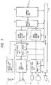
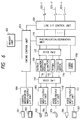
- Fig. 1 is an overall block diagram of a TV telephone set according to a first example of the present invention, wherein 1 is a handset which is one of the voice input means of the present apparatus, 2 is an ON/OFF hook detection unit for detecting whether the handset 1 is placed in the on hook or off hook state, 3 is a microphone which is one of the voice input means of the present invention, 4 is a speaker which is one of the voice output means of the present apparatus for outputting a tone such as a dial tone, a ring back tone, a busy tone, or a reception sound according to the present invention, 5 is an echo canceller unit which is connected to the microphone 3 and the speaker 4 for cancelling an echo generated when both are concurrently used, 6 is a voice processor unit which is connected to the handset 1 and the echo canceller unit 5 for switching the handset 1, the microphone 3 and the speaker 4 and generating a tone to be output to the speaker 4 such as a dial toner, a ring back tone, a busy tone, and a reception tone, 7 is a voice encode/
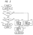
- step S11 the control unit 15 monitors an incoming call at vacancy time, and if the communication unit 14 receives an incoming call primitive, the processing proceeds to steps S12 and S13.
- steps S12 and S13 whether the incoming call is from a TV telephone (step S12) or a telephone (step S13) is judged by investigating information factors such as a transmission ability indicated in the incoming call primitive received, a lower layer matching or a higher layer matching property. As the result, if the incoming call is from the TV telephone, the processing proceeds to step S15, while if it is from the telephone, the processing proceeds to step S16, or otherwise the processing proceeds to step S14 where the incoming call is rejected because of unmatching of the incoming call, and the program terminates.
- the control unit 15 selects a first reception sound 6a for informing the operator of the incoming call for TV telephone.
- the control unit 15 selects a second reception sound 6b for informing the operator of the incoming call for telephone.
- the above-mentioned first and second reception sounds are different in timbres and intermission intervals.
- the processing proceeds to step S17, where the control unit 15 instructs the voice processing unit 6 to generate the reception sound selected at step S15 or S16, and designates the speaker 4 as an output device.
- the voice processing unit 6 generates the reception sound which was selected and instructed, and output it to the speaker 4.
- the control unit 15 is placed in a call reception state after execution of step S17 to wait for a response from the operator.
- the operator can discriminate between an incoming call from TV telephone and that from telephone, by virtue of the difference between the reception sounds, but may be informed of a voice message prestored in the voice processing unit 6, for example, "Incoming call from TV telephone” or "Incoming call from telephone” to identify them.
- a voice message prestored in the voice processing unit 6, for example, "Incoming call from TV telephone” or "Incoming call from telephone” to identify them.
- the input of this voice message can be performed with the handset 1 or microphone 3.
- steps S21 to S24 in the figure correspond to steps S11 to S14 as shown in Fig. 2, respectively, and as the content of execution for each step are the same as that for corresponding step, the explanation thereof will be omitted.
- a first reception call notice screen 10a for informing the operator of an incoming call from a TV telephone which has been prestored is selected.
- a second reception call notice screen 10b for informing the operator of an incoming call from a telephone is selected.
- the processing proceeds to step S27, where the control unit 15 instructs the video processing unit 10 to display the incoming call notice screen selected at step S25 to S26.
- the video processing unit 10 converts an instructed image plane into video signals and outputs them to the display 9.
- the control unit 15 is placed in a call reception state to wait for a response from the operator.
- the first reception call notice screen 10a and the second reception call notice screen 10b are images input from the TV camera 8 or preset therein.
- the operator is informed of the discrimination between an incoming call from a TV telephone and from a telephone, by virtue of the content of image plane, but may be also informed of the discrimination by, for example, a difference in blinkings or colors of a lamp provided.
- selection means may be provided for selecting one of the methods as described in the example for indicating the incoming call, i.e., method of changing the reception sound and that of changing the image plane, in which the operator can select either method of indicating the incoming call, or concurrently implement both indications of changing the reception sound and image plane.
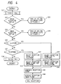
- FIG. 4 A control flowchart in this case is shown in Fig. 4.
- step S31 if an incoming call is accepted, the processing proceeds to step S32.
- steps S32 and S33 the operator determines which reception notice is selected among three forms of voice, image, or both voice and image.
- the processing proceeds from step S32 to step S33, where the processing of S12 and ensuing steps in Fig. 2 are performed.
- the processing proceeds from step S34 to step S35, where the processings of S22 and ensuing steps in Fig. 3 are performed.
- step S34 the processing proceeds from step S34 to step S36.
- steps S36 and S37 a partner's terminal functional capability received is judged, wherein if the incoming call is judged to be from a TV telephone, the processing proceeds to step S39, while if it is judged to be from a telephone, the processing proceeds to step S41, or otherwise, the processing proceeds to step S38.
- the incoming call is from a TV telephone
- the reception sound for a TV telephone 6a is selected at step S39 and the reception image plane for TV telephone 10a is selected at step S40.
- the reception sound for telephone 6b is selected at step S41 and the reception image plane for telephone 10b is selected at step S42.
- step S43 the reception sound selected at step S39 or S41 is generated, and at step S44, the reception image plane selected at step S40 or S41 is displayed.
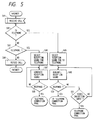
- step S47 When reception from telephone is made, at step S47, the reception sound for telephone which was selected at step S46 is generated. Thereafter, if the response is entered with an off-hook of handset by the operator, the processing proceeds from step S48 to the telephone connection processing, thereby enabling the transmission with voice.
- step S49 When reception from TV telephone occurs, at step S49, the reception sound for TV telephone which was selected at step S45 is generated. Afterwards, if the response is entered with an off-hook of handset by the operator, the processing proceeds from step S50 to the TV telephone connection processing, thereby enabling the transmission with voice and video. On the other hand, if an input for inhibiting the transmission of video is performed by the operator after the reception sound is generated at step S49, the processing proceeds from step S51 to the telephone connection processing. In this case, any video information is not transmitted to a partner's equipment, and the transmission with only voice is enabled.
- the transmission of an imprudent image can be prevented and the privacy of an operator can be protected because the transmission of only voice can be selected when responding by inhibiting the transmission of video after an incoming call from a TV telephone has been recognized.
- Fig. 6 is a block diagram showing the configuration of a TV telephone set according to the second example of the present invention.
- 101 is a control information input unit (for example, a keyboard or a ten key) used for the input of control information to perform the overall control of the present apparatus, wherein it is connected via a control information input/output interface unit 108 for controlling the input/output of control information to an entire control unit 121.
- the control information input/output interface unit 108 is connected with a control information output unit 102 such as a monitor for displaying the control information.
- a voice input unit 103 such as a microphone and a voice output unit 104 such as a speaker are connected via a first voice input/output interface unit 109 for controlling the input/output of voice signals to a first voice switch 112, which is connected via a second voice input/output interface unit 110 to a voice input/output unit 105 such as a handset.
- the first voice switch 112 is connected to a 64kbps A-law PCM voice codec (encoder/decoder unit) 113, a 64kbps ⁇ -law PCM voice codec 114, a 16kbps voice codec 115, and 7 KHz voice associated SB-ADPCM voice codec 116, with these voice codecs 113 to 116 being connected via a second voice switch 117 to a multiplication/separation unit 119.
- the voice codecs 113 to 116 are to encode and decode in accordance with the respective encode/ decode rules, in which the present apparatus can cope with four rules.
- the first and second voice switches 112, 117 can select any one of these codecs.
- a video input unit 106 such as a camera and a video output unit 107 such as a monitor are connected via a video input/output interface unit 111 for controlling the input/output of video signals to a video codec 118, which is connected to the multiplication/separation unit 119.
- the video codec 118 encodes and decodes the video information in accordance with a predetermined rule.
- the multiplication/separation unit 119 is connected via the entire control unit 121 and a line control interface control unit 120 to the lines 123-1, 123-2, ..., 123-n, to multiplex various media into frames for information transmission and separate received frames into voice and video.
- the line interface control unit 20 is connected to the entire control unit 121, which controls the connection between the present apparatus and the line.
- the entire control unit 121 is connected to a memory unit 122, which stores various control information of the whole apparatus, and an information table for partner's terminal functional capability per partner's number and operator's terminal functional capability to be exchanged with partner's terminal.
- the entire control unit 121 controls the whole apparatus in accordance with the control information from the control unit 108 and the memory unit 122.
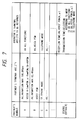
- Fig. 7 is a table showing the numbers of other terminals (partner's number) stored as a functional capability management table classified by the partner's number in the memory unit 122, the partner's terminal functional capability and the operator's terminal functional capability to be returned in the capability or functionality exchange with the partner's terminal.
- a partner's terminal with the number A for example, is capable of the AV communication, which indicates that video animation is communicable at a transmission rate of 108.8kbps at maximum, with the voice ability of dealing with the modes of A-law PCM, ⁇ -law PCM and SB-ADPCM, and the operator's terminal ability to be notified to the partner's terminal is "all functions".
- a partner's terminal with the number B is able to communicate at a transmission rate of 62.4 kbps at maximum in video, and in voice, communicable in the PCM mode, while indicating that only the voice PCM should be returned from the present apparatus as the operator's terminal functional capability. This means that the transmission of video is not desired for the partner with the number B.
- the voice PCM is notified to the partner's terminal as the operator's terminal capability, and in transmitting to the unregistered terminal, one of the functions, the voice PCM (A-law, ⁇ -law) or the telephone mode with which the partner's terminal can cope with is notified as the operator's terminal capability.
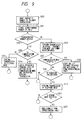
- Fig. 8 is a flowchart showing the operation at reception time in the present apparatus.
- a Set-up message is received as an incoming call in the Dch call control.
- step S101 whether or not the current incoming call is a telephone call is determined with the parameters of BC (Bearer Capability) and HLC (High Layer Compatibility) in this Set up message. If it is a telephone call (the answer at step S101 is yes), the processing proceeds to step S110, where the communication is started by returning a call setting accept response, and when received from a partner unregistered in the aforementioned ability management table classified by partner's number, data associated with the partner's terminal are registered and the contents of the table are updated.
- step S102 it is determined whether or not the reception is in the AV communication mode. There are currently some cases where this determination can not be made in this phase, and in such cases, the determination is made in the in-channel procedure after the establishment of call setting response accept connection at step S103. If it is not the AV communication (the answer at step S102 is no), there is a possibility of enabling the reception within a range supported by the terminal, thus transferring to another processing. If it is the AV communication mode (the answer at step S102 is yes), the synchronization of connection is established after the establishment of call setting response accept connection at step S103.
- the corresponding number is searched in the management table as shown in Fig. 7, to determine whether or not the partner is registered. If the corresponding partner's number is registered (the answer at step S104 is yes), an operator's terminal ability indication corresponding to the partner is picked up with reference to the operator's terminal ability to be returned (notified) in the management table, and the ability or functionality is returned in the ability exchange sequence (step S105). Further, the management table of Fig. 7 is updated as required by referring to a partner's terminal ability to be transmitted from the partner, or the new information is added to the management table. Next, after the execution of the mode switching sequence at step S106, the mutual communication is started in a predetermined mode.
- step S104 For example, for an incoming call in the AV communication mode from a partner with the number B as shown in the management table, only PCM voice is notified to the partner as the operator's ability as the communication mode with animation being not desired, with the result that the mutual communication mode with the PCM voice alone is selected. If the corresponding partner's number does not exist at step S104 (the answer is no at step S104), the processing proceeds to step S107, where the operator's terminal ability to be returned which is registered in the management table as the default is exchanged, and the communication in a predetermined mode is started at step S108. In this case, the present example enables the mode only with the PCM voice.
- step S109 the partner's ability which is transmitted from the partner is added to the management table as a new data, while at the same time registering the operator's ability to be returned as the communication mode with the partner.
- a management table for use with temporary change is stored in the memory unit 122, apart from the management table as shown in Fig. 7, and the management table for use is changed in accordance with an instruction of user.
- a partner's number is input to indicate the transmission.
- the corresponding number is searched in the management table.
- the processing proceeds to step S203.
- step S203 If the partner is not provided with the AV communication mode (the answer at step S203 is no), the call transmission is made automatically in the telephone mode for the telephone mode communication (step S205). If the corresponding number does not exist at step S202 (the answer at step S202 is no), the processing proceeds to step S206, where the call transmission is performed in the default AV communication mode.
- step S207 it is determined whether or not the call transmission is accepted in the AV communication mode from the present apparatus, and if accepted (the answer at step S207 is yes), the default ability exchange is performed at step S208 and additionally, the ability which has been transmitted from the partner is added to the management table as a new data. Thereafter, the AV communication mode with respect to the corresponding partner is changed as required, and the operator's terminal ability to be returned is updated.
- step S207 If the transmission in the AV communication mode is not accepted at step S207 (the answer at step S207 is no), the processing proceeds to step S209, where a determination is made whether or not the reason is owing to "attribute mismatching", i.e., the partner's terminal being without the AV communication mode, and if not (the answer at step S209 is no), the reason is displayed and the communication is terminated. In case of "attribute mismatching" (the answer at step S209 is yes), the processing proceeds to step S210, where the call transmission in the telephone mode is automatically made.
- step S211 If it is accepted at step S211 (the answer at step S211 is yes), the processing proceeds to step S212, where the partner's terminal attribute allowing only for the telephone mode is added to the management table as a new data. If it is not accepted (the answer at step S211 is no), the reason is displayed and the communication is terminated.
- a TV telephone set since the operator's terminal ability to be returned to a partner can be changed based on a partner number or a temporarily set mode when receiving in the AV communication mode, the user's privacy can be protected by preventing the AV communication with video from being made to anyone unnecessarily, and coping with flexibly in the case where the video is not desired to be transmited, temporarily. Further, even when transmitting to any partner's terminal, an efficient connection with the partner's terminal can be accomplished in the optimal mode by referring to the management table, and without any clear instruction by an operator as regards whether or not the partner is capable of the AV communication. This respect is significantly important especially in the period or the system in which a normal telephone and a TV telephone are mixed.
- the privacy of a user can be protected in communicating to the unregistered partner's terminal.
- the change of partner's terminal ability can be rapidly followed, and the efficient connection with a partner that has once been communicated with is enabled in the optimal mode in the subsequent communications.
- the operator's terminal ability to be returned to a partner is determined basically based on the management table of Fig. 7, or changed based on a temporary instruction, it is also possible to switch the communication mode with respect to the partner during communication temporarily or to update the return ability. Further, the AV communication mode can be determined based not only on the partner's number but also on the special information exchanged in the extension mode of BAS in the subaddress or in-channel.
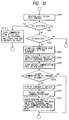
- Fig. 10 is a flowchart showing the operation of another example at reception time.
- Steps S300 - S303 and S310 are the same as those of steps S100 - S103 and S110 as previously shown in Fig. 8.
- step S 303 i.e., after the synchronization for connection in the AV communication mode has been established, the operator's terminal ability is made capable only of the PCM voice communication, the ability exchange sequence is performed in accordance with the procedure of the CCITT recommendation draft H.242 as previously described, and the partner's terminal ability to be received from the partner's terminal is stored in the memory unit 22 (step S304). At the same time, the content of the management table as shown in Fig. 7 is updated or added as required by referring to the management table. Next, at step S305, the mutual communication only in the PCM voice is started, whereby the partner can be truly known.
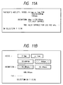
- step S306 if a user of corresponding terminal determines that the video communiction to the partner is capable or desired to make (the answer at step S306 is yes), the processing proceeds to step S307, where the partner's ability is displayed in the control information output unit 102, for example, as shown in Fig. 11A.
- the user of the apparatus selects a communication mode by switching into a selection screen as shown in Fig. 11B, for selecting the optimal mode in view of the partner's terminal ability and the operator's terminal ability (or may select on the same screen).
- step S309 the ability exchange sequence is again performed in accordance with the procedure of aforementioned H.242, and after switching into a desired communication mode in the mode switching sequence, the mutual communication is performed. If the video communication is not perfomred at step S306 (the answer at step S306 is no), the communication is continued in the current state.
- the present example when receiving from a partner's terminal, mutual communication only in the PCM voice is first performed, and after the confirmation of a communication partner and the partner's terminal ability, mutual communication with video is performed only if a user of the apparatus desires the communication with video, thereby preventing the AV communicability of an operator's terminal from being notified to the partner's terminal unnecessarily, and protecting the privacy of user.
- the communication mode can be selected after a user of the partner's terminal is confirmed through the voice communication, the present apparatus is effective in such a case where a plurality of users are assumed in one partner's terminal, and a part of users are not desired for the communication by video.
- the PCM voice communication is necessarily performed once at reception time, and the communication mode is reset after the confirmation of a partner
- the AV communication with video can be started with a specific partner unconditionally if there is no designation.
- the partner's ability may not be displayed every time in switching the communication mode during communication, but the mode switching can be instructed in one touch with a special key or the like so as to be performed promptly in accordance with the communication mode stored in the management table.
Landscapes
- Engineering & Computer Science (AREA)
- Signal Processing (AREA)
- Computer Networks & Wireless Communication (AREA)
- Multimedia (AREA)
- Two-Way Televisions, Distribution Of Moving Picture Or The Like (AREA)
Description
- The present invention relates to a voice and video communication apparatus capable of communicating voice information, and video information such as animation or still image.
- Conventionally, there was provided a telephone capable of discriminating, for example, between incoming calls from an extension and those from an outside line, by changing the timbre or intermission intervals of reception sound for the telephone.
- On the other hand, there was a disadvantage that when a TV telephone set capable of communicating both voice and video information was connected to the telephone line and used together with a telephone set, it was difficult to discriminate between incoming calls from the TV telephone and those from the telephone.
- By the way, in ISDN, when a call is received, the communication attributes (transmission ability information factor, lower layer matching information factor, higher layer matching information factor) are notified to equipment at the reception side. However, an operator at the reception side is not informed of whether the incoming call was intended for voice alone or voice with image, for example, based on those communication attributes.
- Thus in a communication apparatus capable of communicating both voice and video, there was conventionally a problem that as an operator was not informed of the difference between an incoming call from telephone and that from TV telephone, an operator's indiscrete appearance might be transmitted to a partner with the TV telephone, if the operator responds to the incoming call inappropriately.
- Recently, as the communication service with the ISDN line has been put to practical use, the AV (Audio Visual) service such as a TV telephone or a TV conference system which uses such digital lines comes to public notice, and the service rules for AV service, the protocol rules, and the multi-media multiplication frame structure regulations are published as, for example, the CCITT (International Telegraph and Telephone Consultative Committee) recommendation drafts H.320, H.242, H.221 and the like. The draft H.221 defines the coding allocation of BAS (Bit Allocation Signal) which is used for the frame structure and terminal ability exchange, the terminal mode switching, or the bit allocation indication in the AV service on a channel from 64Kbps to 1,920Kbps. The draft H.242 defines the protocol procedure between AV terminals, and the draft H.320 defines the system aspect of the entire AV service. The recommendation drafts in association with AGC (Audio Graphic Conference) are also examined successively.
- The above drafts define a procedure for selecting a mutual communication with the highest ability between terminals, with a procedure such as a terminal ability exchange sequence with BAS between in-channels or a mode switching sequence, after the establishment of the physical connection and synchronization for end-to-end operation.
- Thus, since a conventional terminal responds automatically to an accepted incoming call in accordance with the terminal ability or functionality, the video communication ability of an operator's terminal is notified to a partner's terminal undesirable for the mutual communication of video if it is provided. Thereby, there was a disadvantage that a video was automatically transmitted also to a partner's terminal which did not desire to communicate by video.
- In this way, in a conventional TV telephone set capable of communicating both voice and video, the protection of privacy of a terminal user was a consideration.
- US Patent Specification US-A-3,933,233 discloses a combined video/voice data communication system which does not automatically provide privacy if required, whilst EP-A-0,355,838 is concerned with facsimile/voice operation and thus does not present the same problem.
- Thus the present invention is concerned with resolving the above-described disadvantages on the conventional technology and providing voice and video communication apparatus capable of protecting the privacy of a terminal user.
- Thus an embodiment of the present invention provides a voice and video communication apparatus capable of automatically setting the transmission or non-transmission of video information, depending on a partner for transmission.
- A described embodiment of the present invention provides a voice and video communication apparatus capable of informing its operator of an incoming call while indicating clearly whether the incoming call is from a TV telephone or a telephone.
- An embodiment of the present invention also provides a communication apparatus capable of informing its operator of an incoming call from a TV telephone or a telephone by only displaying a corresponding image, thereby preventing incoming sound from disturbing a conference in progress.
- The present invention can also provide a communication apparatus capable of preventing the undesired transmission of a careless image and protecting the privacy of its operator, because the transmission of only voice can be selected to respond by inhibiting the transmission of video after the incoming call of the TV telephone is recognized.
- Another embodiment of the present invention provides a communication apparatus capable of protecting the privacy of its operator by inhibiting the AV transmission with video to every partner's terminal, because the functional capability of an operator's terminal to be notified to a partner's terminal can be changed depending on the transmission partner.
- Another embodiment of the present invention provides a communication apparatus capable of enhancing the operability of a terminal, for example, such that at a time when it is desired to disable temporarily the transmission with video to all the partner's terminals, the operator can easily make a temporary change of his terminal's functional capability to be notified to a partner's terminal.
- Another embodiment of the present invention provides a communication apparatus capable of protecting the privacy of its operator even when communicating with an unregistered terminal, because a predetermined operator's terminal functional capability is notified to the unregistered partner's terminal.
- A further embodiment of the present invention provides a communication apparatus capable of rapidly coping with the change of a partner's terminal functional capability, and making an efficient connection to a partner's terminal that has once been communicated with, in the optimal mode on the subsequent communications, because the information about a registered partner's terminal is updated to be newest, or the information about an unregistered partner's terminal is added, during communication.
- Another embodiment of the present invention provides a communication apparatus capable of protecting the privacy of a user by preventing the AV communicability of an operator's terminal from being notified to a partner's terminal unnecessarily, because a voice communication mode is first performed in receiving, and then a communication mode other than the voice communication mode is enabled as desired by an operator, after the confirmation of a communication partner and a partner's terminal functional capability.
- In order that the present invention may be more readily understood, embodiments thereof will now be described by way of example and in conjunction with the accompanying drawings, in which:
- Fig. 1 is a block diagram or a TV telephone set according to a first example of the present invention;
- Fig. 2 is a flowchart of the informing procedure of an incoming call executed in a
control section 15 of Fig. 1; - Figs. 3, 4 and 5 are flowcharts showing another example of the informing procedure of an incoming call;
- Fig. 6 is a block diagram of a TV telephone set according to a second example of the present invention;
- Fig. 7 is a view showing an functional capability management table classified by partner's number;
- Fig. 8 is a flowchart showing the operation at reception time in the TV telephone set of Fig. 6;
- Fig. 9 is a flowchart showing the operation at transmission time in the TV telephone set of Fig. 6;
- Fig. 10 is a flowchart showing the operation at reception time according to another example; and
- Figs. 11A and 11B are views showing image plane examples of a control information output unit.
- An example of the present invention will be described with reference to the drawings.
- Fig. 1 is an overall block diagram of a TV telephone set according to a first example of the present invention, wherein 1 is a handset which is one of the voice input means of the present apparatus, 2 is an ON/OFF hook detection unit for detecting whether the
handset 1 is placed in the on hook or off hook state, 3 is a microphone which is one of the voice input means of the present invention, 4 is a speaker which is one of the voice output means of the present apparatus for outputting a tone such as a dial tone, a ring back tone, a busy tone, or a reception sound according to the present invention, 5 is an echo canceller unit which is connected to the microphone 3 and the speaker 4 for cancelling an echo generated when both are concurrently used, 6 is a voice processor unit which is connected to thehandset 1 and theecho canceller unit 5 for switching thehandset 1, the microphone 3 and the speaker 4 and generating a tone to be output to the speaker 4 such as a dial toner, a ring back tone, a busy tone, and a reception tone, 7 is a voice encode/decode unit connected to thevoice processing unit 6, for encoding a transmission voice signal and decoding an incoming voice signal in accordance with a voice signal encode and decode algorithm such as 64kPCM A-law, 64kPCM µ-law, 64kSB-ADPCM, 32kADPCM, or 16kAPC-AB, 8 is a TV camera for inputting an image, 9 is a display for displaying an operator's image input from theTV camera 8, a partner's image received, an incoming call notice screen or an operation screen according to the present invention, a communication state, or messages, 10 is a video processing unit connected to theTV camera 8 and thedisplay 9 for performing the signal synthesis to display the operator's image and the partner's image onto a screen being segmented, 11 is an image encode/decode unit connected to thevideo processing unit 10 for encoding a transmission image and decoding a reception image according to CCITT recommendation H.261, 12 is an operation unit such as keyboard or touch panel, 13 is a multiplexer unit connected to the voice encode/decode unit 7 and the image encode/decode unit 11 for multiplexing and demultiplexing voice data, image data and other data in accordance with CCITT recommendation H.221, 14 is a communication unit connected to themultiplexer unit 13 for controlling the line in accordance with the ISDN user and network interface, and 15 is a control unit connected to eachunit - An informing procedure of an incoming call to an operator on the reception side, which is performed in the
control unit 15 of a TV telephone set with an above constitution, will be described with reference to a flowchart of control program as shown in Fig. 2. - First, at step S11, the
control unit 15 monitors an incoming call at vacancy time, and if the communication unit 14 receives an incoming call primitive, the processing proceeds to steps S12 and S13. At steps S12 and S13, whether the incoming call is from a TV telephone (step S12) or a telephone (step S13) is judged by investigating information factors such as a transmission ability indicated in the incoming call primitive received, a lower layer matching or a higher layer matching property. As the result, if the incoming call is from the TV telephone, the processing proceeds to step S15, while if it is from the telephone, the processing proceeds to step S16, or otherwise the processing proceeds to step S14 where the incoming call is rejected because of unmatching of the incoming call, and the program terminates. - At step S15, the
control unit 15 selects afirst reception sound 6a for informing the operator of the incoming call for TV telephone. At step S16, thecontrol unit 15 selects asecond reception sound 6b for informing the operator of the incoming call for telephone. The above-mentioned first and second reception sounds are different in timbres and intermission intervals. After execution of steps S15 or S16, the processing proceeds to step S17, where thecontrol unit 15 instructs thevoice processing unit 6 to generate the reception sound selected at step S15 or S16, and designates the speaker 4 as an output device. Thevoice processing unit 6 generates the reception sound which was selected and instructed, and output it to the speaker 4. Thecontrol unit 15 is placed in a call reception state after execution of step S17 to wait for a response from the operator. - In the above example, the operator can discriminate between an incoming call from TV telephone and that from telephone, by virtue of the difference between the reception sounds, but may be informed of a voice message prestored in the
voice processing unit 6, for example, "Incoming call from TV telephone" or "Incoming call from telephone" to identify them. Here the input of this voice message can be performed with thehandset 1 or microphone 3. - As described above, it is possible to make the operator clearly recognize that an incoming call is from a TV telephone or a telephone, by detecting the matching of the incoming call and outputting either of the reception sounds as a result of this detection.
- Next, another example of the informing procedure of an incoming call as shown in Fig. 2 will be described with reference to a control program flowchart as shown in Fig. 3. Note that steps S21 to S24 in the figure correspond to steps S11 to S14 as shown in Fig. 2, respectively, and as the content of execution for each step are the same as that for corresponding step, the explanation thereof will be omitted.
- At step S25, a first reception call notice screen 10a for informing the operator of an incoming call from a TV telephone which has been prestored is selected. At step S26, a second reception
call notice screen 10b for informing the operator of an incoming call from a telephone is selected. After execution of steps S25 or S26, the processing proceeds to step S27, where thecontrol unit 15 instructs thevideo processing unit 10 to display the incoming call notice screen selected at step S25 to S26. Thevideo processing unit 10 converts an instructed image plane into video signals and outputs them to thedisplay 9. After execution of step S27, thecontrol unit 15 is placed in a call reception state to wait for a response from the operator. Note that the first reception call notice screen 10a and the second receptioncall notice screen 10b are images input from theTV camera 8 or preset therein. - In the above example, the operator is informed of the discrimination between an incoming call from a TV telephone and from a telephone, by virtue of the content of image plane, but may be also informed of the discrimination by, for example, a difference in blinkings or colors of a lamp provided.
- Further, selection means may be provided for selecting one of the methods as described in the example for indicating the incoming call, i.e., method of changing the reception sound and that of changing the image plane, in which the operator can select either method of indicating the incoming call, or concurrently implement both indications of changing the reception sound and image plane.
- A control flowchart in this case is shown in Fig. 4.
- At step S31, if an incoming call is accepted, the processing proceeds to step S32. At steps S32 and S33, the operator determines which reception notice is selected among three forms of voice, image, or both voice and image. When the voice reception notice is selected, the processing proceeds from step S32 to step S33, where the processing of S12 and ensuing steps in Fig. 2 are performed. When the image reception notice is selected, the processing proceeds from step S34 to step S35, where the processings of S22 and ensuing steps in Fig. 3 are performed.
- When the voice and image reception notice is selected, the processing proceeds from step S34 to step S36. At steps S36 and S37, a partner's terminal functional capability received is judged, wherein if the incoming call is judged to be from a TV telephone, the processing proceeds to step S39, while if it is judged to be from a telephone, the processing proceeds to step S41, or otherwise, the processing proceeds to step S38. When the incoming call is from a TV telephone, the reception sound for a
TV telephone 6a is selected at step S39 and the reception image plane for TV telephone 10a is selected at step S40. When the incoming call is from a telephone, the reception sound fortelephone 6b is selected at step S41 and the reception image plane fortelephone 10b is selected at step S42. At step S43, the reception sound selected at step S39 or S41 is generated, and at step S44, the reception image plane selected at step S40 or S41 is displayed. - Next, an example in which the transmisson of video information to a partner can be inhibited after an incoming call from a TV telephone is notified to the operator and responded, will be described with reference to Fig. 5. The following explanation is based on an example of changing the reception sound depending on whether the reception is from a telephone or a TV telephone, but can be also applied to a case where the reception image plane is changed with both reception sound and reception image.
- In Fig. 5, the processings at steps S41 to S46 correspond to steps S11 to S26 in Fig. 2.
- When reception from telephone is made, at step S47, the reception sound for telephone which was selected at step S46 is generated. Thereafter, if the response is entered with an off-hook of handset by the operator, the processing proceeds from step S48 to the telephone connection processing, thereby enabling the transmission with voice.
- When reception from TV telephone occurs, at step S49, the reception sound for TV telephone which was selected at step S45 is generated. Afterwards, if the response is entered with an off-hook of handset by the operator, the processing proceeds from step S50 to the TV telephone connection processing, thereby enabling the transmission with voice and video. On the other hand, if an input for inhibiting the transmission of video is performed by the operator after the reception sound is generated at step S49, the processing proceeds from step S51 to the telephone connection processing. In this case, any video information is not transmitted to a partner's equipment, and the transmission with only voice is enabled.
- As described above, it is possible to inform the operator of an incoming call while indicating clearly whether the call is from a TV telephone or a telephone, by detecting the matching of the incoming call, and outputting either of the reception sounds or image planes so as to inform about the reception of a call from a TV telephone and that from a telephone in accordance with the detection result obtained.
- Further, it is possible to make the operator recognize whether an incoming call is from a TV telephone or a telephone by informing about the call by an image only, so that for example a conference in progress will not be disturbed.
- Further, according to the present invention, the transmission of an imprudent image can be prevented and the privacy of an operator can be protected because the transmission of only voice can be selected when responding by inhibiting the transmission of video after an incoming call from a TV telephone has been recognized.
- Next, a second example in which the transmission or non-transmission of video can be automatically set depending on a communication partner will be described.
- Fig. 6 is a block diagram showing the configuration of a TV telephone set according to the second example of the present invention. In the same figure, 101 is a control information input unit (for example, a keyboard or a ten key) used for the input of control information to perform the overall control of the present apparatus, wherein it is connected via a control information input/
output interface unit 108 for controlling the input/output of control information to anentire control unit 121. The control information input/output interface unit 108 is connected with a controlinformation output unit 102 such as a monitor for displaying the control information. - A
voice input unit 103 such as a microphone and avoice output unit 104 such as a speaker are connected via a first voice input/output interface unit 109 for controlling the input/output of voice signals to afirst voice switch 112, which is connected via a second voice input/output interface unit 110 to a voice input/output unit 105 such as a handset. Thefirst voice switch 112 is connected to a 64kbps A-law PCM voice codec (encoder/decoder unit) 113, a 64kbps µ -lawPCM voice codec 114, a16kbps voice codec 115, and 7 KHz voice associated SB-ADPCM voice codec 116, with thesevoice codecs 113 to 116 being connected via asecond voice switch 117 to a multiplication/separation unit 119. The voice codecs 113 to 116 are to encode and decode in accordance with the respective encode/ decode rules, in which the present apparatus can cope with four rules. The first and second voice switches 112, 117 can select any one of these codecs. - On the other hand, a
video input unit 106 such as a camera and avideo output unit 107 such as a monitor are connected via a video input/output interface unit 111 for controlling the input/output of video signals to avideo codec 118, which is connected to the multiplication/separation unit 119. Thevideo codec 118 encodes and decodes the video information in accordance with a predetermined rule. - The multiplication/
separation unit 119 is connected via theentire control unit 121 and a line controlinterface control unit 120 to the lines 123-1, 123-2, ..., 123-n, to multiplex various media into frames for information transmission and separate received frames into voice and video. The line interface control unit 20 is connected to theentire control unit 121, which controls the connection between the present apparatus and the line. Theentire control unit 121 is connected to amemory unit 122, which stores various control information of the whole apparatus, and an information table for partner's terminal functional capability per partner's number and operator's terminal functional capability to be exchanged with partner's terminal. Theentire control unit 121 controls the whole apparatus in accordance with the control information from thecontrol unit 108 and thememory unit 122. - Fig. 7 is a table showing the numbers of other terminals (partner's number) stored as a functional capability management table classified by the partner's number in the
memory unit 122, the partner's terminal functional capability and the operator's terminal functional capability to be returned in the capability or functionality exchange with the partner's terminal. In the same figure, a partner's terminal with the number A, for example, is capable of the AV communication, which indicates that video animation is communicable at a transmission rate of 108.8kbps at maximum, with the voice ability of dealing with the modes of A-law PCM, µ-law PCM and SB-ADPCM, and the operator's terminal ability to be notified to the partner's terminal is "all functions". And a partner's terminal with the number B is able to communicate at a transmission rate of 62.4 kbps at maximum in video, and in voice, communicable in the PCM mode, while indicating that only the voice PCM should be returned from the present apparatus as the operator's terminal functional capability. This means that the transmission of video is not desired for the partner with the number B. - Further, when a reception is made from a partner's terminal with a number which is not registered in the management table (thereafter called an "unregistered terminal"), only the voice PCM is notified to the partner's terminal as the operator's terminal capability, and in transmitting to the unregistered terminal, one of the functions, the voice PCM (A-law, µ-law) or the telephone mode with which the partner's terminal can cope with is notified as the operator's terminal capability.
- Fig. 8 is a flowchart showing the operation at reception time in the present apparatus.
- First, at step S100, a Set-up message is received as an incoming call in the Dch call control. At step S101, whether or not the current incoming call is a telephone call is determined with the parameters of BC (Bearer Capability) and HLC (High Layer Compatibility) in this Set up message. If it is a telephone call (the answer at step S101 is yes), the processing proceeds to step S110, where the communication is started by returning a call setting accept response, and when received from a partner unregistered in the aforementioned ability management table classified by partner's number, data associated with the partner's terminal are registered and the contents of the table are updated. If the incoming call is not a telephone call (the answer at step S101 is no), the processing proceeds to step S102, where it is determined whether or not the reception is in the AV communication mode. There are currently some cases where this determination can not be made in this phase, and in such cases, the determination is made in the in-channel procedure after the establishment of call setting response accept connection at step S103. If it is not the AV communication (the answer at step S102 is no), there is a possibility of enabling the reception within a range supported by the terminal, thus transferring to another processing. If it is the AV communication mode (the answer at step S102 is yes), the synchronization of connection is established after the establishment of call setting response accept connection at step S103. At step S104, the corresponding number is searched in the management table as shown in Fig. 7, to determine whether or not the partner is registered. If the corresponding partner's number is registered (the answer at step S104 is yes), an operator's terminal ability indication corresponding to the partner is picked up with reference to the operator's terminal ability to be returned (notified) in the management table, and the ability or functionality is returned in the ability exchange sequence (step S105). Further, the management table of Fig. 7 is updated as required by referring to a partner's terminal ability to be transmitted from the partner, or the new information is added to the management table. Next, after the execution of the mode switching sequence at step S106, the mutual communication is started in a predetermined mode. For example, for an incoming call in the AV communication mode from a partner with the number B as shown in the management table, only PCM voice is notified to the partner as the operator's ability as the communication mode with animation being not desired, with the result that the mutual communication mode with the PCM voice alone is selected. If the corresponding partner's number does not exist at step S104 (the answer is no at step S104), the processing proceeds to step S107, where the operator's terminal ability to be returned which is registered in the management table as the default is exchanged, and the communication in a predetermined mode is started at step S108. In this case, the present example enables the mode only with the PCM voice. At step S109, the partner's ability which is transmitted from the partner is added to the management table as a new data, while at the same time registering the operator's ability to be returned as the communication mode with the partner.
- Note that though in the above example, the operator's terminal ability to be returned to the partner is switched completely based on the management table of Fig. 7, it is also possible to set temporarily by the input with a control key or the like such that the PCM voice mode only is returned to every partner. In this case, a management table for use with temporary change is stored in the
memory unit 122, apart from the management table as shown in Fig. 7, and the management table for use is changed in accordance with an instruction of user. - Next, the operation of the present apparatus at transmission time will be described in detail with reference to a flowchart as shown in Fig. 9.
- First, at step S200, a partner's number is input to indicate the transmission. At step S201, the corresponding number is searched in the management table. At step S202, whether or not the corresponding number searched is determined (the answer at step S202 is yes), the processing proceeds to step S203. At step S203, it is determined whether or not the corresponding partner is capable of the AV communication mode, and if so (the answer at step S203 is yes), the call transmission is made in the AV communication mode at step S204, the operator's terminal ability set in the management table in the AV communication mode is notified to a partner, after which the mutual communication is performed within a predetermined mode. If the partner is not provided with the AV communication mode (the answer at step S203 is no), the call transmission is made automatically in the telephone mode for the telephone mode communication (step S205). If the corresponding number does not exist at step S202 (the answer at step S202 is no), the processing proceeds to step S206, where the call transmission is performed in the default AV communication mode. At step S207, it is determined whether or not the call transmission is accepted in the AV communication mode from the present apparatus, and if accepted (the answer at step S207 is yes), the default ability exchange is performed at step S208 and additionally, the ability which has been transmitted from the partner is added to the management table as a new data. Thereafter, the AV communication mode with respect to the corresponding partner is changed as required, and the operator's terminal ability to be returned is updated.
- If the transmission in the AV communication mode is not accepted at step S207 (the answer at step S207 is no), the processing proceeds to step S209, where a determination is made whether or not the reason is owing to "attribute mismatching", i.e., the partner's terminal being without the AV communication mode, and if not (the answer at step S209 is no), the reason is displayed and the communication is terminated. In case of "attribute mismatching" (the answer at step S209 is yes), the processing proceeds to step S210, where the call transmission in the telephone mode is automatically made. If it is accepted at step S211 (the answer at step S211 is yes), the processing proceeds to step S212, where the partner's terminal attribute allowing only for the telephone mode is added to the management table as a new data. If it is not accepted (the answer at step S211 is no), the reason is displayed and the communication is terminated.
- As above described, in a TV telephone set according to the present example, since the operator's terminal ability to be returned to a partner can be changed based on a partner number or a temporarily set mode when receiving in the AV communication mode, the user's privacy can be protected by preventing the AV communication with video from being made to anyone unnecessarily, and coping with flexibly in the case where the video is not desired to be transmited, temporarily. Further, even when transmitting to any partner's terminal, an efficient connection with the partner's terminal can be accomplished in the optimal mode by referring to the management table, and without any clear instruction by an operator as regards whether or not the partner is capable of the AV communication. This respect is significantly important especially in the period or the system in which a normal telephone and a TV telephone are mixed.
- Further, as a predetermined operator's terminal ability is notified in the management table when receiving from an unregistered partner's terminal or transmitting to such an unregistered terminal, the privacy of a user can be protected in communicating to the unregistered partner's terminal.
- Further, as the content of the management table for a partner's terminal is updated during communication to the partner's terminal, or new information is added, the change of partner's terminal ability can be rapidly followed, and the efficient connection with a partner that has once been communicated with is enabled in the optimal mode in the subsequent communications.
- Note that though in the above examples, the operator's terminal ability to be returned to a partner is determined basically based on the management table of Fig. 7, or changed based on a temporary instruction, it is also possible to switch the communication mode with respect to the partner during communication temporarily or to update the return ability. Further, the AV communication mode can be determined based not only on the partner's number but also on the special information exchanged in the extension mode of BAS in the subaddress or in-channel.
- Fig. 10 is a flowchart showing the operation of another example at reception time.
- Steps S300 - S303 and S310 are the same as those of steps S100 - S103 and S110 as previously shown in Fig. 8.
- After the execution of step S 303, i.e., after the synchronization for connection in the AV communication mode has been established, the operator's terminal ability is made capable only of the PCM voice communication, the ability exchange sequence is performed in accordance with the procedure of the CCITT recommendation draft H.242 as previously described, and the partner's terminal ability to be received from the partner's terminal is stored in the memory unit 22 (step S304). At the same time, the content of the management table as shown in Fig. 7 is updated or added as required by referring to the management table. Next, at step S305, the mutual communication only in the PCM voice is started, whereby the partner can be truly known. At step S306, if a user of corresponding terminal determines that the video communiction to the partner is capable or desired to make (the answer at step S306 is yes), the processing proceeds to step S307, where the partner's ability is displayed in the control
information output unit 102, for example, as shown in Fig. 11A. Here, the user of the apparatus selects a communication mode by switching into a selection screen as shown in Fig. 11B, for selecting the optimal mode in view of the partner's terminal ability and the operator's terminal ability (or may select on the same screen). Next, at step S309, the ability exchange sequence is again performed in accordance with the procedure of aforementioned H.242, and after switching into a desired communication mode in the mode switching sequence, the mutual communication is performed. If the video communication is not perfomred at step S306 (the answer at step S306 is no), the communication is continued in the current state. - In this way, according to the present example, when receiving from a partner's terminal, mutual communication only in the PCM voice is first performed, and after the confirmation of a communication partner and the partner's terminal ability, mutual communication with video is performed only if a user of the apparatus desires the communication with video, thereby preventing the AV communicability of an operator's terminal from being notified to the partner's terminal unnecessarily, and protecting the privacy of user. Particularly, according to the present example, as the communication mode can be selected after a user of the partner's terminal is confirmed through the voice communication, the present apparatus is effective in such a case where a plurality of users are assumed in one partner's terminal, and a part of users are not desired for the communication by video.
- Note that though in the above example, the PCM voice communication is necessarily performed once at reception time, and the communication mode is reset after the confirmation of a partner, the AV communication with video can be started with a specific partner unconditionally if there is no designation. Further, the partner's ability may not be displayed every time in switching the communication mode during communication, but the mode switching can be instructed in one touch with a special key or the like so as to be performed promptly in accordance with the communication mode stored in the management table.
- As above described, the following effects can be obtained according to the second example of the present invention:
- (1) As the ability of an operator's terminal to be notified to a partner's terminal can be changed depending on a communication partner, the AV communication with video to all the partner's terminals can be inhibited and the privacy of an operator can be protected.
- (2) As an operator can easily perform the temporary change of his terminal capability to be notified to a partner's terminal, the operability of terminal can be enhanced, for example, when it is desired to inhibit temporarily the communication with video to all the partner's terminals.
- (3) As a predetermined operator's terminal ability is notified to an unregistered partner's terminal, the privacy of a user can be protected even when communication with unregistered terminal.
- (4) As the information about a registered partner's terminal is updated in the operator's terminal to be newest during communication, or the information about an unregistered partner's terminal is added, the change of the partner's terminal ability can-be followed promptly, and the efficient connection to a partner's terminal that has once been communicated with can be accomplished in the optimal mode on the subsequent communications.
- (5) As the voice communication mode is first performed in receiving, and a communication mode other than the voice communication is enabled in accordance with an operator's desire, after the confirmation of a communication partner and the partner terminal ability, the AV communicability of an operator's terminal is prevented from being notified to a partner's terminal unnecessarily and thus the privacy of a user can be protected. Particularly, the present apparatus is effective, for example, when a plurality of users are assumed in one partner's terminal and a part of users are not desired for the communication with video.
Claims (5)
- A communication terminal comprising:
voice and video communication means (109,111) adapted to be connected to a plurality of other terminals, and characterised in that it further comprises memory means (122) for storing and determining the functional capability of the terminal in respect of each of a plurality of said other terminals; notification means (121) for giving notice of the appropriate stored functional capability of said terminal to one of said other terminals when a call is received from or transmitted to said one other terminal; and
control means for controlling the operation of said voice and video communication means in accordance with the stored functional capability of the terminal as notified by said notification means. - A terminal according to claim 1, further comprising change memory means for changing and storing temporarily the functional capability of the terminal which is to be notified to at least one of said other terminals, and wherein said notification means is operative to notify the temporarily stored functional capability when a call is sent to or received from said one other terminal.
- A terminal according to any one of the preceding claims wherein in addition to storing the functional capability of the terminal in respect of said plurality of other terminals, said memory means stores a functional capability to be notified to unregistered terminals which are other than said plurality of other terminals when a call is received from one of said unregistered terminals.
- A terminal according to claim 3, wherein said memory means stores a functional capability to be notified to an unregistered terminal when a call is made to an unregistered terminal.
- A terminal according to any one of the preceding claims and further comprising means for updating the information stored in said memory means in respect both of the functional capability of said terminal and the functional capability of one or more of said other terminals.
Applications Claiming Priority (4)
| Application Number | Priority Date | Filing Date | Title |
|---|---|---|---|
| JP64888/90 | 1990-03-15 | ||
| JP6488890A JPH03265349A (en) | 1990-03-15 | 1990-03-15 | ISDN-connected videophone device |
| JP2089794A JP3010055B2 (en) | 1990-04-03 | 1990-04-03 | Communication terminal and communication terminal control method |
| JP89794/90 | 1990-04-03 |
Publications (2)
| Publication Number | Publication Date |
|---|---|
| EP0447212A1 EP0447212A1 (en) | 1991-09-18 |
| EP0447212B1 true EP0447212B1 (en) | 1994-12-28 |
Family
ID=26406019
Family Applications (1)
| Application Number | Title | Priority Date | Filing Date |
|---|---|---|---|
| EP91302121A Expired - Lifetime EP0447212B1 (en) | 1990-03-15 | 1991-03-13 | Voice and video communication apparatus |
Country Status (3)
| Country | Link |
|---|---|
| US (1) | US5510829A (en) |
| EP (1) | EP0447212B1 (en) |
| DE (1) | DE69106183T2 (en) |
Families Citing this family (39)
| Publication number | Priority date | Publication date | Assignee | Title |
|---|---|---|---|---|
| JPH0530502A (en) * | 1991-07-24 | 1993-02-05 | Hitachi Ltd | Integrated video phone |
| DE4131062C1 (en) * | 1991-09-18 | 1992-11-05 | Siemens Ag, 8000 Muenchen, De | |
| US5581560A (en) * | 1993-08-27 | 1996-12-03 | Canon Kabushiki Kaisha | Communication apparatus and method for simultaneous communication of audio and data signals with improved audio control |
| JPH07193619A (en) * | 1993-10-27 | 1995-07-28 | Canon Inc | Digital telephone and its operating method |
| US6111935A (en) * | 1993-10-27 | 2000-08-29 | Canon Kabushiki Kaisha | Adaptive expansion table in a digital telephone receiver |
| DE69432246D1 (en) | 1993-12-29 | 2003-04-17 | Canon Kk | Communication device for multimedia information |
| JPH07336462A (en) * | 1994-06-03 | 1995-12-22 | Canon Inc | Communication terminal and communication system |
| US5802281A (en) | 1994-09-07 | 1998-09-01 | Rsi Systems, Inc. | Peripheral audio/video communication system that interfaces with a host computer and determines format of coded audio/video signals |
| US5969749A (en) * | 1994-11-04 | 1999-10-19 | Canon Kabushiki Kaisha | Apparatus and method for suspending a reproduction operation reproducing image information when the arrival of a call from a communication line is detected |
| KR100281526B1 (en) * | 1996-07-08 | 2001-02-15 | 윤종용 | Video telephone system with voice / video telephone mode switching function and switching method thereof |
| US5905940A (en) * | 1997-02-04 | 1999-05-18 | Arvisais; Georges J. | Video communication method |
| US6104802A (en) | 1997-02-10 | 2000-08-15 | Genesys Telecommunications Laboratories, Inc. | In-band signaling for routing |
| US6480600B1 (en) | 1997-02-10 | 2002-11-12 | Genesys Telecommunications Laboratories, Inc. | Call and data correspondence in a call-in center employing virtual restructuring for computer telephony integrated functionality |
| US7031442B1 (en) | 1997-02-10 | 2006-04-18 | Genesys Telecommunications Laboratories, Inc. | Methods and apparatus for personal routing in computer-simulated telephony |
| KR100261606B1 (en) * | 1997-06-30 | 2000-07-15 | 이중구 | Digital camera possible for telecommunication |
| US6259469B1 (en) * | 1997-09-05 | 2001-07-10 | Nikon Corporation | Information processing device, information processing method, and recording media |
| US5966165A (en) * | 1997-09-19 | 1999-10-12 | 8×8, Inc. | Videophone interface arrangement and method therefor |
| US6985943B2 (en) | 1998-09-11 | 2006-01-10 | Genesys Telecommunications Laboratories, Inc. | Method and apparatus for extended management of state and interaction of a remote knowledge worker from a contact center |
| US6711611B2 (en) | 1998-09-11 | 2004-03-23 | Genesis Telecommunications Laboratories, Inc. | Method and apparatus for data-linking a mobile knowledge worker to home communication-center infrastructure |
| USRE46528E1 (en) | 1997-11-14 | 2017-08-29 | Genesys Telecommunications Laboratories, Inc. | Implementation of call-center outbound dialing capability at a telephony network level |
| US7907598B2 (en) | 1998-02-17 | 2011-03-15 | Genesys Telecommunication Laboratories, Inc. | Method for implementing and executing communication center routing strategies represented in extensible markup language |
| US6332154B2 (en) | 1998-09-11 | 2001-12-18 | Genesys Telecommunications Laboratories, Inc. | Method and apparatus for providing media-independent self-help modules within a multimedia communication-center customer interface |
| US6621514B1 (en) * | 1998-03-12 | 2003-09-16 | Intel Corporation | Video conferencing system |
| US6775361B1 (en) * | 1998-05-01 | 2004-08-10 | Canon Kabushiki Kaisha | Recording/playback apparatus with telephone and its control method, video camera with telephone and its control method, image communication apparatus, and storage medium |
| USRE46153E1 (en) | 1998-09-11 | 2016-09-20 | Genesys Telecommunications Laboratories, Inc. | Method and apparatus enabling voice-based management of state and interaction of a remote knowledge worker in a contact center environment |
| US6687515B1 (en) * | 1998-10-07 | 2004-02-03 | Denso Corporation | Wireless video telephone with ambient light sensor |
| WO2000069158A1 (en) * | 1999-05-06 | 2000-11-16 | Kyocera Corporation | Videophone system using cellular telephone terminal |
| US7587337B1 (en) * | 2000-03-24 | 2009-09-08 | Eastman Kodak Company | Leasing configured camera system |
| US8046270B2 (en) * | 2000-05-19 | 2011-10-25 | Eastman Kodak Company | System and method for providing image products and/or services |
| US7929978B2 (en) | 1999-12-01 | 2011-04-19 | Genesys Telecommunications Laboratories, Inc. | Method and apparatus for providing enhanced communication capability for mobile devices on a virtual private network |
| GB2370188A (en) | 2000-11-01 | 2002-06-19 | Orange Personal Comm Serv Ltd | Mixed-media telecommunication call set-up |
| JP3775346B2 (en) * | 2002-05-29 | 2006-05-17 | 株式会社日立製作所 | Videophone system and terminal device thereof |
| US6879828B2 (en) | 2002-09-09 | 2005-04-12 | Nokia Corporation | Unbroken primary connection switching between communications services |
| US7609286B2 (en) * | 2004-01-08 | 2009-10-27 | Sorenson Communications, Inc. | Method and apparatus for video conferencing |
| JP4895557B2 (en) * | 2005-09-16 | 2012-03-14 | パナソニック株式会社 | Multi-carrier communication apparatus and multi-carrier communication method |
| US9008075B2 (en) | 2005-12-22 | 2015-04-14 | Genesys Telecommunications Laboratories, Inc. | System and methods for improving interaction routing performance |
| CN101547240A (en) * | 2008-03-26 | 2009-09-30 | 鸿富锦精密工业(深圳)有限公司 | Digital information device and method thereof for processing call |
| DE102008059582B4 (en) * | 2008-11-28 | 2019-05-09 | Bernd Baranski | mobile phone |
| US8941706B2 (en) | 2010-04-07 | 2015-01-27 | Apple Inc. | Image processing for a dual camera mobile device |
Family Cites Families (19)
| Publication number | Priority date | Publication date | Assignee | Title |
|---|---|---|---|---|
| US3933233A (en) * | 1974-01-02 | 1976-01-20 | Stromberg-Carlson Corporation | Control circuit for subscriber station in video telephone system |
| US3917904A (en) * | 1974-05-30 | 1975-11-04 | Gte Automatic Electric Lab Inc | Video telephone subscriber interface circuit |
| DE2842777A1 (en) * | 1978-09-30 | 1980-04-03 | Licentia Gmbh | PARTICIPANT DETECTION METHOD |
| JPS5571382A (en) * | 1978-11-24 | 1980-05-29 | Hitachi Ltd | Buffer memory dispersive arrangement-type picture sound transmission system |
| ATE33741T1 (en) * | 1983-02-10 | 1988-05-15 | Krone Ag | METHOD AND DEVICE FOR SIGNALING BETWEEN VIDEOPHONES IN AN EXISTING TELEPHONE CONNECTION. |
| FR2562746B1 (en) * | 1984-04-10 | 1986-08-08 | Sorriaux Pierre | STICKERS WITH VIDEO SWITCHING MATRIX |
| US4932047A (en) * | 1985-11-07 | 1990-06-05 | Luma Telecom, Inc. | Conversational video phone |
| JPS63129747A (en) * | 1986-11-20 | 1988-06-02 | Canon Inc | Picture communication equipment |
| DE3640680A1 (en) * | 1986-11-28 | 1988-06-09 | Siemens Ag | IMAGE SPEAKER |
| JPS6474155A (en) * | 1987-09-17 | 1989-03-20 | Miyako Jidosha Kogyo Kk | Tandem master cylinder |
| DE3856152T2 (en) * | 1987-10-30 | 1998-11-05 | Luma Telecom Inc | Still picture telephone communication system |
| JPH01212056A (en) * | 1988-02-18 | 1989-08-25 | Toshiba Corp | Video telephone equipment |
| US5204895A (en) * | 1988-03-22 | 1993-04-20 | Canon Kabushiki Kaisha | Data communicating apparatus which selects analog or digital communication in accordance with the destination number |
| JPH06101770B2 (en) * | 1988-06-10 | 1994-12-12 | 富士通株式会社 | ISDN compound terminal |
| JP2998960B2 (en) * | 1988-08-26 | 2000-01-17 | キヤノン株式会社 | Communication method |
| JPH02113761A (en) * | 1988-10-24 | 1990-04-25 | Nippon Telegr & Teleph Corp <Ntt> | Television telephone system |
| JPH02158250A (en) * | 1988-12-09 | 1990-06-18 | Fujitsu Ltd | Automatic telephone directory preparation system for isdn terminal equipment |
| JPH036162A (en) * | 1989-06-01 | 1991-01-11 | Mitsubishi Electric Corp | Image/voice transmission device |
| US5305097A (en) * | 1989-12-20 | 1994-04-19 | Canon Kabushiki Kaisha | Communicating apparatus having a calling party number display device |
-
1991
- 1991-03-13 EP EP91302121A patent/EP0447212B1/en not_active Expired - Lifetime
- 1991-03-13 DE DE69106183T patent/DE69106183T2/en not_active Expired - Fee Related
-
1994
- 1994-09-26 US US08/319,058 patent/US5510829A/en not_active Expired - Lifetime
Also Published As
| Publication number | Publication date |
|---|---|
| US5510829A (en) | 1996-04-23 |
| EP0447212A1 (en) | 1991-09-18 |
| DE69106183T2 (en) | 1995-06-22 |
| DE69106183D1 (en) | 1995-02-09 |
Similar Documents
| Publication | Publication Date | Title |
|---|---|---|
| US5510829A (en) | Voice and video communication apparatus | |
| US5381412A (en) | Multimedia communication apparatus | |
| US5524194A (en) | Data communication apparatus | |
| KR0126461B1 (en) | Communication system with ISDN signal capability | |
| EP0380315B1 (en) | TV phone communication system and apparatus therefor | |
| US20030035523A1 (en) | System and method for virtual multiline telephony in a home-network telephone | |
| EP0282158B1 (en) | Communication system | |
| JP3278825B2 (en) | Image communication telephone and image communication method | |
| JP3010055B2 (en) | Communication terminal and communication terminal control method | |
| JPH09261364A (en) | Digital AV system | |
| JPH10341326A (en) | G4 facsimile adapter | |
| JPH04238452A (en) | Composite type picture communication equipment | |
| JP3273962B2 (en) | Multimedia communication equipment | |
| JPH0330560A (en) | Facsimile equipment | |
| JPH0715538A (en) | Terminal device | |
| JP2800962B2 (en) | Communication control device for copier | |
| JP3061444B2 (en) | Multimedia communication equipment | |
| JPH07123172A (en) | Terminal device | |
| JP3204195B2 (en) | Facsimile machine | |
| JP4027336B2 (en) | Multimedia communication apparatus and communication method of multimedia communication apparatus | |
| JPH04207253A (en) | Visual telephone set | |
| JP2710133B2 (en) | Facsimile machine | |
| JPH04223755A (en) | Multimedia terminal and its control method | |
| JPH05167710A (en) | Multimedia communication system | |
| JP2928300B2 (en) | Transmission control method for ISDN terminal device |
Legal Events
| Date | Code | Title | Description |
|---|---|---|---|
| PUAI | Public reference made under article 153(3) epc to a published international application that has entered the european phase |
Free format text: ORIGINAL CODE: 0009012 |
|
| AK | Designated contracting states |
Kind code of ref document: A1 Designated state(s): DE FR GB |
|
| 17P | Request for examination filed |
Effective date: 19920210 |
|
| 17Q | First examination report despatched |
Effective date: 19930429 |
|
| GRAA | (expected) grant |
Free format text: ORIGINAL CODE: 0009210 |
|
| AK | Designated contracting states |
Kind code of ref document: B1 Designated state(s): DE FR GB |
|
| REF | Corresponds to: |
Ref document number: 69106183 Country of ref document: DE Date of ref document: 19950209 |
|
| ET | Fr: translation filed | ||
| PLBE | No opposition filed within time limit |
Free format text: ORIGINAL CODE: 0009261 |
|
| STAA | Information on the status of an ep patent application or granted ep patent |
Free format text: STATUS: NO OPPOSITION FILED WITHIN TIME LIMIT |
|
| 26N | No opposition filed | ||
| REG | Reference to a national code |
Ref country code: GB Ref legal event code: IF02 |
|
| PGFP | Annual fee paid to national office [announced via postgrant information from national office to epo] |
Ref country code: GB Payment date: 20090331 Year of fee payment: 19 |
|
| PGFP | Annual fee paid to national office [announced via postgrant information from national office to epo] |
Ref country code: DE Payment date: 20090331 Year of fee payment: 19 |
|
| PGFP | Annual fee paid to national office [announced via postgrant information from national office to epo] |
Ref country code: FR Payment date: 20090325 Year of fee payment: 19 |
|
| GBPC | Gb: european patent ceased through non-payment of renewal fee |
Effective date: 20100313 |
|
| REG | Reference to a national code |
Ref country code: FR Ref legal event code: ST Effective date: 20101130 |
|
| PG25 | Lapsed in a contracting state [announced via postgrant information from national office to epo] |
Ref country code: FR Free format text: LAPSE BECAUSE OF NON-PAYMENT OF DUE FEES Effective date: 20100331 |
|
| PG25 | Lapsed in a contracting state [announced via postgrant information from national office to epo] |
Ref country code: DE Free format text: LAPSE BECAUSE OF NON-PAYMENT OF DUE FEES Effective date: 20101001 |
|
| PG25 | Lapsed in a contracting state [announced via postgrant information from national office to epo] |
Ref country code: GB Free format text: LAPSE BECAUSE OF NON-PAYMENT OF DUE FEES Effective date: 20100313 |