EP0447249A2 - Interpolation seismischer Spuren - Google Patents
Interpolation seismischer Spuren Download PDFInfo
- Publication number
- EP0447249A2 EP0447249A2 EP91302201A EP91302201A EP0447249A2 EP 0447249 A2 EP0447249 A2 EP 0447249A2 EP 91302201 A EP91302201 A EP 91302201A EP 91302201 A EP91302201 A EP 91302201A EP 0447249 A2 EP0447249 A2 EP 0447249A2
- Authority
- EP
- European Patent Office
- Prior art keywords
- trace
- dip
- dips
- frequency components
- seismic
- Prior art date
- Legal status (The legal status is an assumption and is not a legal conclusion. Google has not performed a legal analysis and makes no representation as to the accuracy of the status listed.)
- Withdrawn
Links
Images


Classifications
-
- G—PHYSICS
- G01—MEASURING; TESTING
- G01V—GEOPHYSICS; GRAVITATIONAL MEASUREMENTS; DETECTING MASSES OR OBJECTS; TAGS
- G01V1/00—Seismology; Seismic or acoustic prospecting or detecting
- G01V1/28—Processing seismic data, e.g. for interpretation or for event detection
-
- G—PHYSICS
- G01—MEASURING; TESTING
- G01V—GEOPHYSICS; GRAVITATIONAL MEASUREMENTS; DETECTING MASSES OR OBJECTS; TAGS
- G01V2210/00—Details of seismic processing or analysis
- G01V2210/50—Corrections or adjustments related to wave propagation
- G01V2210/57—Trace interpolation or extrapolation, e.g. for virtual receiver; Anti-aliasing for missing receivers
Definitions
- This invention pertains to interpolation of seismic data from a plurality of recorded seismic traces and more specifically by performing a dip range analysis on a plurality of seismic traces and by examining the trace envelope of the seismic traces.
- Interpolation methods in the prior art generally attempt to estimate a new trace by connecting the troughs and peaks representing reflected arrivals in recorded traces algong a dip, a dip being defined as the rate of change in the time of arrival per trace. These methods typically examine the recorded traces along a number of preselected experimental dips in order to determine the correct dip of the reflected arrivals and thereafter interpolate a reflected arrival in the new trace along the correct dip. Alternately, interpolated traces may be generated by inserting zero traces at the interpolation locations and following with an appropriate spatial filter. This alternate approach requires that the signal dips be approximately known a priori.
- Aliasing is defined as the condition wherein a dip is sufficiently large so that there is difficulty in correlating the peaks and troughs in successive recorded traces, typically when successive traces are greater than or equal to one half cycle out of phase.
- the prior art also fails when the recorded traces exhibit a plurality of dips because of an inability to adequately separate the reflected arrivals.
- a method for interpolating seismic data which comprises: establishing a trace window containing a plurality of seismic traces over a period of time, selecting a plurality of dips defining a plurality of dip ranges within said trace window, generating a trace estimate for each of said dip ranges, comprising the steps of, filtering each one of a plurality of frequency components of said seismic traces by mathematically integrating a time shift in said frequency components across the time period in the trace defined by each said dip range, and summing said filtered frequency components, demodulating each of said seismic traces to obtain the respective trace envelopes, generating a weighting function for each of said dips as a measure of the extent to which said dip corresponds with an actual dip, weighting each of said trace estimates with the weighting function of said trace estimate's respective dip, and summing said weighted trace estimates to generate an interpolated trace.
- the present invention performs an analysis on a plurality of dip ranges defined by a preselected number of experimental dips in a trace window of seismic traces for a given period of time.
- a trace estimate is first generated for each of the dip ranges by filtering each of the frequency components of each trace in the dip range by mathematically integrating a time shift in those components and then summing them.
- the filtered frequency components may be passed through a low pass filter and/or tapered before being summed.
- the seismic traces are also demodulated to obtain their respective trace envelopes from which their weighting functions correlated to the continuity of the envelope amplitudes along the experimental dips are derived.
- the trace estimates are then multiplied with the weighting functions to obtain weighted trace estimates that are then summed to generate the interpolated trace.
- the weighting functions may alternatively be defined to be the normalized ratios of the square of the mean of the trace envelope values of the trace envelopes along the experimental dips to the variance of said values.
- Fig. 1 illustrates the trace window containing a plurality of seismic traces among which one or more new traces are to be interpolated.
- Fig. 2 is an enlarged view of a portion of the trace window in Fig. 1 illustrating the experimental dips and their corresponding dip ranges.
- Fig. 3 illustrates the trace envelopes obtained by demodulating the seismic traces in Fig. 1.
- Fig. 4 illustrates the variation of the trace envelope amplitudes along the centers of the dip ranges.
- Fig. 5 is the plot of the trace envelope amplitudes in each dip range with respect to the positions of the traces in the trace window.
- Fig. 6 depicts the trace estimates for each dip range.
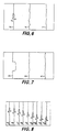
- Fig. 7 illustrates the weighting functions derived from the trace envelope amplitudes along the center of the dip ranges illustrated in Figs. 4 and 5.
- Fig. 8 illustrates the relationship of the interpolated trace as inserted among the remainder of the recorded traces in the trace window of Fig. 1.
- seismic surveying It is well known in the art of seismic surveying that data resulting from the surveys is recorded in the form of seismic traces.
- the practice of seismic surveying typically employs a seismic source and a number of receivers.
- the source generates an energy wave and directs it toward the geological formation that reflects the energy to the receivers at or near the ground surface.
- the receivers detect the reflected arrivals and record them in the form of seismic traces, one trace per receiver, and then the traces are compiled to complete the survey.
- These techniques have also been adapted for marine environments. The practice of these techniques has long been familiar to those ordinarily skiled in the art.
- Fig. 1 illustrates a trace window containing a prularity of seismic traces 15-22 generated by a seismic survey and an interpolation location 10 where it is desired to insert an interpolated trace to provide information undected by the survey.
- Seismic traces 15-22 contain wavelets 30-37 that are aliased with respect to each other indicating reflected arrivals along actual dip 12.
- the following discussion discloses the use of the method to perform a single interpolation over a single time sample represented by the trace window.
- the invention may be practised with a trace window containing varying numbers of interpolation locations, seismic traces, or dips, but the disclosure herein is narrowed for the sake of clarity.
- a portion of the trace window in Fig. 1 is illustrated in greater detail and the features in Fig. 2 having counterparts in Fig. 1 are numbered in like manner.
- wavelets 32a and 33a in Fig. 2 are the counterparts of wavelets 32 and 33 in Fig. 1.
- Each of the seismic traces 17a-20a is composed of a plurality of frequency components.
- a trace estimate is generated for each dip range between experimental dips 55-58 by filtering each of the frequency components of each of the seismic traces appearing in that range and then summing the filtered frequency components.
- ⁇ time
- the integrand of Eq. 1 is a filter which will generate a constant time shift, and the prior art employs it, for example, to shift a particular point in the seismic trace, i.e., t1 or t2, to a selected reference point 50.
- the method disclosed herein has achieved superior results by shifting the group of points on the recorded trace 20a in the dip range between t1 and t2 to the selected reference point 50 as heretofore described.
- Eq. 1 is modified to include a tapering function which is applied in the outside (i.e, minimum and maximum dip ranges: Wherein:
- tapering functions optional to the implementation of the method but does facilitate the interpretation of the data set after the method has been practised. Tapering functions are well known in the art and there are many other such functions which would produce satisfactory results. It is therefore noted that the practice of the method herein described is not to be limited to the use of Eq. (4) but may encompass any other tapering function which will yield desirable results.
- the traces depicted in Fig. 1 are then demodulated as is well known in the art to obtain the trace envelopes depicted in Fig. 3.
- Trace envelopes 65-72 in Fig. 3 correspond to seismic traces 15-22 in Fig. 1, respectively.
- interpolation position 10c in Fig. 3 corresponds to interpolation position 10 in Fig. 1.
- the trace envelopes may be generated either before or after the construction of the trace estimates heretofore described as long as both steps are performed before the trace estimates are weighted as will hereinafter be discussed.
- the trace envelopes are then analyzed for continuity in amplitude in the dip ranges as is illustrated in Figs. 4 and 5.
- Fig. 4 is an enlarged view of selected trace envelopes in Fig. 3 with dips 55a-57a corresponding to the centers of the dip ranges defined by experimental dips 55-58 of Fig. 2.
- Dip 55a is centered in the dip range defined by experimental dips 55 and 56
- dip 56a in the dip range defined experimental dips 56 and 57
- dip 57a is in the dip range defined by experimental dips 57 and 58.
- Trace envelopes 67a-70a and interpolation position 10d correspond to trace envelopes 67-70 and interpolation position 10c in Fig. 3, respectively.
- Fig. 5 plots the trace envelope amplitudes in each dip range along dips 55a-57a as a function of each trace envelope's position in the trace window.
- Plots 53b-57b are the graphical representations for dips 55a-57a, respectively.
- the analysis in Figs. 4 and 5 could alternatively be performed either by substituting experimental dips 55-58 for dips 55a-57a or by a dip range analysis as was employed for generating the trace estimates.
- the amplitude of the traces along dip 55a is fairly large and continuous while those along dips 56a and 57a are not.
- Continuity in amplitude indicates that the dip range being examined corresponds to an actual dip in data represented by the recorded seismic traces 15-22 of the trace window depicted in Fig. 1.
- the lack of continuity in plots 56b and 57b likewise indicates that those experimental dips do not correspond to actual dips in the data.
- ⁇ the mean of the trace envelope values
- ⁇ 2 variance of the trace envelope values.
- any one of a number of other continuity factors may be used in place of Eq. (5) to obtain acceptable results.
- Another factor which might be taken into account in developing a continuity factor is whether a reflector in the geological formation is particularly strong and continuous. If so, its dip weights can be spread above and below the reflector to encourage the same dips at nearby times.
- the continuity factors are then normalized by summing them and then dividing them by the total number of continuity factors to generate the weighting functions pictured in Fig. 7. For instance, weighting functions 85-87, one for each of the experimental dips 55a-57a, will be generated for the seismic trace 20a in dip range 26 of Fig. 2. Trace estimates 75-77 of Fig. 6 likewise correspond to the dip ranges defined by experimental dips 55-58 of a single trace such as 20a in Fig. 2. The weighting functions in Fig. 7 are then multiplied with the trace estimates in Fig. 6 so that each of the trace estimates for each of the experimental dips is weighted. These weighted trace estimates are then summed, the result being the interpolated trace which is inserted into the seismic data at the desired interpolation location as is indicated by the interpolated trace 10b in Fig. 8.
Landscapes
- Engineering & Computer Science (AREA)
- Remote Sensing (AREA)
- Physics & Mathematics (AREA)
- Life Sciences & Earth Sciences (AREA)
- Acoustics & Sound (AREA)
- Environmental & Geological Engineering (AREA)
- Geology (AREA)
- General Life Sciences & Earth Sciences (AREA)
- General Physics & Mathematics (AREA)
- Geophysics (AREA)
- Geophysics And Detection Of Objects (AREA)
Applications Claiming Priority (2)
| Application Number | Priority Date | Filing Date | Title |
|---|---|---|---|
| US07/493,885 US4964098A (en) | 1990-03-15 | 1990-03-15 | Method for seismic trace interpolation |
| US493885 | 1990-03-15 |
Publications (2)
| Publication Number | Publication Date |
|---|---|
| EP0447249A2 true EP0447249A2 (de) | 1991-09-18 |
| EP0447249A3 EP0447249A3 (en) | 1992-04-15 |
Family
ID=23962105
Family Applications (1)
| Application Number | Title | Priority Date | Filing Date |
|---|---|---|---|
| EP19910302201 Withdrawn EP0447249A3 (en) | 1990-03-15 | 1991-03-14 | Seismic trace interpolation |
Country Status (4)
| Country | Link |
|---|---|
| US (1) | US4964098A (de) |
| EP (1) | EP0447249A3 (de) |
| CA (1) | CA2021674A1 (de) |
| NO (1) | NO903370L (de) |
Cited By (2)
| Publication number | Priority date | Publication date | Assignee | Title |
|---|---|---|---|---|
| WO1999003004A1 (en) * | 1997-07-10 | 1999-01-21 | Pgs Tensor, Inc. | Method of detecting seismic events and for detecting and correcting geometry and statics error in seismic data |
| GB2395559A (en) * | 2002-11-19 | 2004-05-26 | Westerngeco Seismic Holdings | Interpolating seismic data |
Families Citing this family (18)
| Publication number | Priority date | Publication date | Assignee | Title |
|---|---|---|---|---|
| CA2083846C (en) * | 1991-03-27 | 1996-03-19 | Tracy J. Stark | Displaying n dimensional data in an n-1 dimensional format |
| US5319554A (en) * | 1991-08-30 | 1994-06-07 | Shell Oil Company | Method for data interpolation and signal enhancement |
| US5235556A (en) * | 1992-01-10 | 1993-08-10 | Halliburton Geophysical Services Inc. | Interpolation of aliased seismic traces |
| US5243563A (en) * | 1992-10-02 | 1993-09-07 | Exxon Production Research Company | Seismic depth imaging |
| US5677892A (en) * | 1996-08-14 | 1997-10-14 | Western Atlas International, Inc. | Unaliased spatial trace interpolation in the f-k domain |
| WO2002023222A1 (en) * | 2000-09-15 | 2002-03-21 | Nutec Sciences, Inc. | Illumination weighted imaging condition for migrated seismic data |
| US7027929B2 (en) * | 2003-11-21 | 2006-04-11 | Geo-X Systems Ltd. | Seismic data interpolation system |
| US7791980B2 (en) * | 2004-05-21 | 2010-09-07 | Westerngeco L.L.C. | Interpolation and extrapolation method for seismic recordings |
| US7388808B2 (en) * | 2004-09-23 | 2008-06-17 | Pgs Americas, Inc. | Method for depth migrating seismic data using pre-stack time migration, demigration, and post-stack depth migration |
| CA2671189C (en) | 2006-11-06 | 2015-12-15 | Magnitude Spas | System, method and computer program product for stacking seismic noise data to analyze seismic events |
| EG24691A (en) * | 2007-01-17 | 2010-05-17 | Pgs Geophysical As | Diagonal gather trace interpolation |
| US7646671B2 (en) * | 2007-12-11 | 2010-01-12 | Pgs Geophysical As | Method for processing marine towed streamer seismic data from regular multi-azimuth surveys |
| WO2010051332A1 (en) | 2008-10-31 | 2010-05-06 | Saudi Arabian Oil Company | A seismic image filtering machine to generate a filtered seismic image, program products, and related methods |
| US8300498B2 (en) * | 2009-06-30 | 2012-10-30 | Pgs Geophysical As | Method for dynamic aperture determination for three-dimensional surface-related multiple elimination |
| CA2831875A1 (en) * | 2011-03-30 | 2012-10-04 | Hunt Energy Enterprises, L.L.C. | Method and system for passive electroseismic surveying |
| US8633700B1 (en) | 2013-03-05 | 2014-01-21 | Hunt Energy Enterprises, Llc | Sensors for passive electroseismic and seismoelectric surveying |
| US8873334B2 (en) | 2013-03-05 | 2014-10-28 | Hunt Energy Enterprises, L.L.C. | Correlation techniques for passive electroseismic and seismoelectric surveying |
| US20160018543A1 (en) * | 2014-07-21 | 2016-01-21 | Westerngeco L.L.C. | Quality check of compressed data sampling interpolation for seismic information |
Family Cites Families (9)
| Publication number | Priority date | Publication date | Assignee | Title |
|---|---|---|---|---|
| US3716829A (en) * | 1970-10-30 | 1973-02-13 | Mobil Oil Corp | Apparatus for and method of treating seismic data having attenuated high frequencies |
| US4570246A (en) * | 1982-02-01 | 1986-02-11 | Chevron Research Company | Method for the interpretation of statistically-related seismic records to yield valuable characteristics, such as gas-bearing potential and lithology of strata |
| US4573148A (en) * | 1982-02-01 | 1986-02-25 | Chevron Research Company | Method for the interpretation of envelope-related seismic records to yield valuable characteristics, such as gas-bearing potential and lithology of strata |
| US4596005A (en) * | 1983-04-20 | 1986-06-17 | Chevron Research Company | Method of seismic collection utilizing multicomponent processing receivers and processing resultant conventional and converted P- or S-wave data |
| US4594693A (en) * | 1983-11-04 | 1986-06-10 | Mobil Oil Corporation | Seismic trace interpolation using f-k filtering |
| US4760563A (en) * | 1986-01-09 | 1988-07-26 | Schlumberger Technology Corporation | Seismic exploration using exactly invertible discrete transformation into tau-p space |
| US4860265A (en) * | 1988-01-25 | 1989-08-22 | Mobil Oil Corporation | Seismic trace restoration using F-K filtering |
| US4887244A (en) * | 1988-06-28 | 1989-12-12 | Mobil Oil Corporation | Method for seismic trace interpolation using a forward and backward application of wave equation datuming |
| US4922465A (en) * | 1989-05-30 | 1990-05-01 | Geco A/S | Interpolation of severely aliased events |
-
1990
- 1990-03-15 US US07/493,885 patent/US4964098A/en not_active Expired - Fee Related
- 1990-07-20 CA CA002021674A patent/CA2021674A1/en not_active Abandoned
- 1990-07-31 NO NO90903370A patent/NO903370L/no unknown
-
1991
- 1991-03-14 EP EP19910302201 patent/EP0447249A3/en not_active Withdrawn
Cited By (4)
| Publication number | Priority date | Publication date | Assignee | Title |
|---|---|---|---|---|
| WO1999003004A1 (en) * | 1997-07-10 | 1999-01-21 | Pgs Tensor, Inc. | Method of detecting seismic events and for detecting and correcting geometry and statics error in seismic data |
| US6208587B1 (en) | 1997-07-10 | 2001-03-27 | Pgs Tensor, Inc. | Method of detecting seismic events and for detecting and correcting geometry and statics error in seismic data |
| GB2395559A (en) * | 2002-11-19 | 2004-05-26 | Westerngeco Seismic Holdings | Interpolating seismic data |
| GB2395559B (en) * | 2002-11-19 | 2006-01-18 | Westerngeco Seismic Holdings | Processing seismic data |
Also Published As
| Publication number | Publication date |
|---|---|
| EP0447249A3 (en) | 1992-04-15 |
| NO903370L (no) | 1991-09-16 |
| CA2021674A1 (en) | 1991-09-16 |
| NO903370D0 (no) | 1990-07-31 |
| US4964098A (en) | 1990-10-16 |
Similar Documents
| Publication | Publication Date | Title |
|---|---|---|
| EP0447249A2 (de) | Interpolation seismischer Spuren | |
| US4853903A (en) | Method and apparatus for removing sinusoidal noise from seismic data | |
| Landisman et al. | Recent improvements in the analysis of surface wave observations | |
| RU2300123C2 (ru) | Высокоразрешающее преобразование радона для обработки сейсмических данных | |
| US2794965A (en) | Statistical interpretation of seismograms | |
| US5648938A (en) | Seismic data acquisition | |
| CA2375495C (en) | Method and apparatus for doppler smear correction in marine seismology measurements | |
| US5067112A (en) | Method for removing coherent noise from seismic data through f-x filtering | |
| US5414674A (en) | Resonant energy analysis method and apparatus for seismic data | |
| US5189644A (en) | Removal of amplitude aliasing effect from seismic data | |
| EP2261693A2 (de) | Rauschunterdrückung in seismischen Daten unter verwendung verbesserter Radon-transformationen | |
| EP0327758A2 (de) | Verfahren zur Trennung von auf- und abgehenden Erreignissen in vertikalen seismischen Messungen | |
| EP0551210B1 (de) | Seismische Untersuchung und Interpolation von unterabgetasteten Spuren | |
| EP0515189B1 (de) | Verfahren zum Dämpfen des Rauschens in seismischen Signalen | |
| US4330872A (en) | Common-offset-distance seismic trace filtering | |
| RU2179732C2 (ru) | Способ снижения уровня помех на сейсмических трассах | |
| US5629904A (en) | Migration process using a model based aperture technique | |
| EP1000369A1 (de) | Verfahren zum generieren von seismischen kennzeichnen und zur seismischen untersuchung | |
| US5051963A (en) | Process for cancelling stationary sinusoidal noise in seismic data | |
| US4397006A (en) | Cross trace coherent noise filtering for seismograms | |
| CA1199409A (en) | Method and apparatus for digital time-variant filtering | |
| EP1532472B1 (de) | Rauschunterdrückung in seismischen daten unter verwendung verbesserter radon-transformationen | |
| US4829487A (en) | Method for restoring seismic data using cross-correlation | |
| Badal et al. | Imaging of shear-wave velocity structure beneath Iberia | |
| Mercer et al. | Long‐range propagation of sound through oceanic mesoscale structures |
Legal Events
| Date | Code | Title | Description |
|---|---|---|---|
| PUAI | Public reference made under article 153(3) epc to a published international application that has entered the european phase |
Free format text: ORIGINAL CODE: 0009012 |
|
| AK | Designated contracting states |
Kind code of ref document: A2 Designated state(s): DE FR GB |
|
| PUAL | Search report despatched |
Free format text: ORIGINAL CODE: 0009013 |
|
| AK | Designated contracting states |
Kind code of ref document: A3 Designated state(s): DE FR GB |
|
| 17P | Request for examination filed |
Effective date: 19921012 |
|
| 17Q | First examination report despatched |
Effective date: 19940425 |
|
| STAA | Information on the status of an ep patent application or granted ep patent |
Free format text: STATUS: THE APPLICATION IS DEEMED TO BE WITHDRAWN |
|
| 18D | Application deemed to be withdrawn |
Effective date: 19940906 |