EP0447317A1 - Verfahren zur Ausbildung einer Falt- oder Trennlinie während der Herstellung eines Verbundwerkstoffteils - Google Patents
Verfahren zur Ausbildung einer Falt- oder Trennlinie während der Herstellung eines Verbundwerkstoffteils Download PDFInfo
- Publication number
- EP0447317A1 EP0447317A1 EP91400682A EP91400682A EP0447317A1 EP 0447317 A1 EP0447317 A1 EP 0447317A1 EP 91400682 A EP91400682 A EP 91400682A EP 91400682 A EP91400682 A EP 91400682A EP 0447317 A1 EP0447317 A1 EP 0447317A1
- Authority
- EP
- European Patent Office
- Prior art keywords
- preform
- masking
- densification
- parts
- infiltration
- Prior art date
- Legal status (The legal status is an assumption and is not a legal conclusion. Google has not performed a legal analysis and makes no representation as to the accuracy of the status listed.)
- Granted
Links
- 239000002131 composite material Substances 0.000 title claims abstract description 16
- 238000000926 separation method Methods 0.000 title claims abstract description 13
- 238000000034 method Methods 0.000 title claims description 22
- 238000004519 manufacturing process Methods 0.000 title claims description 11
- 238000000280 densification Methods 0.000 claims abstract description 30
- 238000001764 infiltration Methods 0.000 claims abstract description 24
- 230000008595 infiltration Effects 0.000 claims abstract description 23
- 230000000873 masking effect Effects 0.000 claims abstract description 21
- 239000000463 material Substances 0.000 claims abstract description 10
- 239000011159 matrix material Substances 0.000 claims abstract description 9
- 239000000126 substance Substances 0.000 claims abstract description 9
- 238000007596 consolidation process Methods 0.000 claims description 10
- 238000000151 deposition Methods 0.000 claims description 3
- 238000002360 preparation method Methods 0.000 claims description 3
- 230000004888 barrier function Effects 0.000 claims 1
- 230000000149 penetrating effect Effects 0.000 claims 1
- 239000000470 constituent Substances 0.000 abstract description 4
- 239000012071 phase Substances 0.000 description 6
- OKTJSMMVPCPJKN-UHFFFAOYSA-N Carbon Chemical compound [C] OKTJSMMVPCPJKN-UHFFFAOYSA-N 0.000 description 5
- ZOKXTWBITQBERF-UHFFFAOYSA-N Molybdenum Chemical compound [Mo] ZOKXTWBITQBERF-UHFFFAOYSA-N 0.000 description 5
- 239000000835 fiber Substances 0.000 description 5
- 229910052750 molybdenum Inorganic materials 0.000 description 5
- 239000011733 molybdenum Substances 0.000 description 5
- 239000012808 vapor phase Substances 0.000 description 5
- 229910002804 graphite Inorganic materials 0.000 description 4
- 239000010439 graphite Substances 0.000 description 4
- 239000004744 fabric Substances 0.000 description 3
- KRHYYFGTRYWZRS-UHFFFAOYSA-N Fluorane Chemical compound F KRHYYFGTRYWZRS-UHFFFAOYSA-N 0.000 description 2
- 239000000919 ceramic Substances 0.000 description 2
- 238000005520 cutting process Methods 0.000 description 2
- 230000008021 deposition Effects 0.000 description 2
- 238000002513 implantation Methods 0.000 description 2
- IUHFWCGCSVTMPG-UHFFFAOYSA-N [C].[C] Chemical class [C].[C] IUHFWCGCSVTMPG-UHFFFAOYSA-N 0.000 description 1
- 239000002253 acid Substances 0.000 description 1
- 230000015572 biosynthetic process Effects 0.000 description 1
- 229910052799 carbon Inorganic materials 0.000 description 1
- 239000011153 ceramic matrix composite Substances 0.000 description 1
- 238000000576 coating method Methods 0.000 description 1
- 210000001520 comb Anatomy 0.000 description 1
- 238000004090 dissolution Methods 0.000 description 1
- 230000008030 elimination Effects 0.000 description 1
- 238000003379 elimination reaction Methods 0.000 description 1
- 238000003754 machining Methods 0.000 description 1
- 230000008018 melting Effects 0.000 description 1
- 238000002844 melting Methods 0.000 description 1
Images


Classifications
-
- C—CHEMISTRY; METALLURGY
- C23—COATING METALLIC MATERIAL; COATING MATERIAL WITH METALLIC MATERIAL; CHEMICAL SURFACE TREATMENT; DIFFUSION TREATMENT OF METALLIC MATERIAL; COATING BY VACUUM EVAPORATION, BY SPUTTERING, BY ION IMPLANTATION OR BY CHEMICAL VAPOUR DEPOSITION, IN GENERAL; INHIBITING CORROSION OF METALLIC MATERIAL OR INCRUSTATION IN GENERAL
- C23C—COATING METALLIC MATERIAL; COATING MATERIAL WITH METALLIC MATERIAL; SURFACE TREATMENT OF METALLIC MATERIAL BY DIFFUSION INTO THE SURFACE, BY CHEMICAL CONVERSION OR SUBSTITUTION; COATING BY VACUUM EVAPORATION, BY SPUTTERING, BY ION IMPLANTATION OR BY CHEMICAL VAPOUR DEPOSITION, IN GENERAL
- C23C16/00—Chemical coating by decomposition of gaseous compounds, without leaving reaction products of surface material in the coating, i.e. chemical vapour deposition [CVD] processes
- C23C16/04—Coating on selected surface areas, e.g. using masks
- C23C16/045—Coating cavities or hollow spaces, e.g. interior of tubes; Infiltration of porous substrates
-
- C—CHEMISTRY; METALLURGY
- C04—CEMENTS; CONCRETE; ARTIFICIAL STONE; CERAMICS; REFRACTORIES
- C04B—LIME, MAGNESIA; SLAG; CEMENTS; COMPOSITIONS THEREOF, e.g. MORTARS, CONCRETE OR LIKE BUILDING MATERIALS; ARTIFICIAL STONE; CERAMICS; REFRACTORIES; TREATMENT OF NATURAL STONE
- C04B35/00—Shaped ceramic products characterised by their composition; Ceramics compositions; Processing powders of inorganic compounds preparatory to the manufacturing of ceramic products
- C04B35/71—Ceramic products containing macroscopic reinforcing agents
- C04B35/78—Ceramic products containing macroscopic reinforcing agents containing non-metallic materials
- C04B35/80—Fibres, filaments, whiskers, platelets, or the like
- C04B35/83—Carbon fibres in a carbon matrix
-
- C—CHEMISTRY; METALLURGY
- C04—CEMENTS; CONCRETE; ARTIFICIAL STONE; CERAMICS; REFRACTORIES
- C04B—LIME, MAGNESIA; SLAG; CEMENTS; COMPOSITIONS THEREOF, e.g. MORTARS, CONCRETE OR LIKE BUILDING MATERIALS; ARTIFICIAL STONE; CERAMICS; REFRACTORIES; TREATMENT OF NATURAL STONE
- C04B37/00—Joining burned ceramic articles with other burned ceramic articles or other articles by heating
- C04B37/003—Joining burned ceramic articles with other burned ceramic articles or other articles by heating by means of an interlayer consisting of a combination of materials selected from glass, or ceramic material with metals, metal oxides or metal salts
- C04B37/005—Joining burned ceramic articles with other burned ceramic articles or other articles by heating by means of an interlayer consisting of a combination of materials selected from glass, or ceramic material with metals, metal oxides or metal salts consisting of glass or ceramic material
-
- C—CHEMISTRY; METALLURGY
- C04—CEMENTS; CONCRETE; ARTIFICIAL STONE; CERAMICS; REFRACTORIES
- C04B—LIME, MAGNESIA; SLAG; CEMENTS; COMPOSITIONS THEREOF, e.g. MORTARS, CONCRETE OR LIKE BUILDING MATERIALS; ARTIFICIAL STONE; CERAMICS; REFRACTORIES; TREATMENT OF NATURAL STONE
- C04B2235/00—Aspects relating to ceramic starting mixtures or sintered ceramic products
- C04B2235/60—Aspects relating to the preparation, properties or mechanical treatment of green bodies or pre-forms
- C04B2235/602—Making the green bodies or pre-forms by moulding
- C04B2235/6028—Shaping around a core which is removed later
-
- C—CHEMISTRY; METALLURGY
- C04—CEMENTS; CONCRETE; ARTIFICIAL STONE; CERAMICS; REFRACTORIES
- C04B—LIME, MAGNESIA; SLAG; CEMENTS; COMPOSITIONS THEREOF, e.g. MORTARS, CONCRETE OR LIKE BUILDING MATERIALS; ARTIFICIAL STONE; CERAMICS; REFRACTORIES; TREATMENT OF NATURAL STONE
- C04B2235/00—Aspects relating to ceramic starting mixtures or sintered ceramic products
- C04B2235/60—Aspects relating to the preparation, properties or mechanical treatment of green bodies or pre-forms
- C04B2235/614—Gas infiltration of green bodies or pre-forms
-
- C—CHEMISTRY; METALLURGY
- C04—CEMENTS; CONCRETE; ARTIFICIAL STONE; CERAMICS; REFRACTORIES
- C04B—LIME, MAGNESIA; SLAG; CEMENTS; COMPOSITIONS THEREOF, e.g. MORTARS, CONCRETE OR LIKE BUILDING MATERIALS; ARTIFICIAL STONE; CERAMICS; REFRACTORIES; TREATMENT OF NATURAL STONE
- C04B2237/00—Aspects relating to ceramic laminates or to joining of ceramic articles with other articles by heating
- C04B2237/30—Composition of layers of ceramic laminates or of ceramic or metallic articles to be joined by heating, e.g. Si substrates
- C04B2237/32—Ceramic
- C04B2237/38—Fiber or whisker reinforced
- C04B2237/385—Carbon or carbon composite
-
- C—CHEMISTRY; METALLURGY
- C04—CEMENTS; CONCRETE; ARTIFICIAL STONE; CERAMICS; REFRACTORIES
- C04B—LIME, MAGNESIA; SLAG; CEMENTS; COMPOSITIONS THEREOF, e.g. MORTARS, CONCRETE OR LIKE BUILDING MATERIALS; ARTIFICIAL STONE; CERAMICS; REFRACTORIES; TREATMENT OF NATURAL STONE
- C04B2237/00—Aspects relating to ceramic laminates or to joining of ceramic articles with other articles by heating
- C04B2237/50—Processing aspects relating to ceramic laminates or to the joining of ceramic articles with other articles by heating
- C04B2237/78—Side-way connecting, e.g. connecting two plates through their sides
Definitions
- the present invention relates to the manufacture of parts made of composite material.
- the present invention relates to the manufacture of structural parts comprising the preparation of a fibrous preform, having substantially the shape of the part to be produced, and the densification of the preform by a matrix obtained by chemical vapor infiltration at within the porosity of the preform.
- This technique is well known, especially for the manufacture of parts made of thermostructural composite materials such as carbon-carbon composites and ceramic matrix composites.
- the fibrous preform is produced from fibrous textures, such as threads, fabrics, veils of fibers, felts, sheets of fibers. These textures can be wound or arranged in superimposed layers. In the latter case, the strata can be linked together by needling or implantation of wires.
- the preform After its preparation, the preform is generally placed in a tool in order to be densified by chemical vapor infiltration.
- the tool usually made of graphite, has the function of maintaining the preform in the desired shape, while ensuring, if necessary, compacting of the preform in order to obtain the desired volume content of fibers (percentage of the apparent volume of the preform actually occupied by the fibers).
- the preform can be removed from the tooling before continuing the vapor phase infiltration until reaching the desired degree of densification.
- a known technique For large parts, a known technique consists in making different parts of a part to be manufactured separately and then assembling these parts.
- the different parts can be done simply at the consolidation stage, that is to say, incompletely densified.
- the part is then obtained by assembling its constituent parts and co-infiltrating them to achieve the desired level of densification.
- the matrix co-infiltrated within the different parts achieves a "bonding" of these due to its continuity at the interfaces between these parts.
- the present invention aims to remedy the aforementioned drawbacks by proposing a method allowing the formation of a fold or separation line during the manufacture of a part made of composite material.
- the method according to the invention is characterized in that a masking is carried out along the or the fold or separation line in order to oppose the infiltration of the constituent material of the matrix in the or each masked zone of the preform, so that after densification the or each masked zone of the preform constitutes a flexible connection integrated into the densified preform.
- the masking of the or each zone of the preform can be maintained until the final degree of densification is reached, so as to obtain a piece of composite material with one or more integrated flexible connections constituting one or more articulation lines .
- the masking of the or each zone of the preform can on the contrary be removed after partial densification or consolidation unmasked parts of the preform.
- the masked zone or zones then constitute flexible connections which allow the preform to be folded to bring it to a shape corresponding to that of the part to be produced.
- the preform infiltration is then continued until reaching the degree of densification. desired end, which stiffens the connections due to the co-infiltration of these and the previously consolidated parts.
- the process according to the invention can also find an application for manufacturing several parts from a single preform, the flexible connections being formed along dividing lines between the parts of the preform corresponding to the different parts During densification, the flexible connections give the preform the deformation capacity necessary to maintain the different parts of it on a conformator. After densification, cuts are made along the separation lines to obtain the different parts.
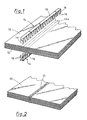
- FIG. 1 illustrates a preform 10 intended for the manufacture of a part made of composite material.
- the preform 10 is formed by flat stacking of layers 12 of a two-dimensional fibrous texture.
- This texture can in particular be constituted by a fabric or a sheet of threads, or also by a complex formed by a layer of fabric or a sheet of threads pre-needled with a veil of fibers.
- a connection between the strata 12 can be achieved by implantation of wires through the superimposed strata or by needling thereof.
- a fold or separation line is reserved on the preform by masking an area thereof corresponding to the fold or separation line to be formed.
- the masking is carried out by means of two covers 14 in the form of combs or brushes applied opposite one another on the two opposite faces of the preform, along the location of the folding or dividing line to be reserved.
- Each cover 14 comprises a strip-shaped part 16 whose width corresponds to that of the line to be formed and which is applied against one face of the preform 10.
- the strip 16 On the side where it is in contact with the preform, the strip 16 is provided teeth 18 whose length is equal to or almost equal to the thickness of the preform.
- the teeth 18 of a cover penetrate the preform and are each housed between two teeth of the other cover.
- at least one of the covers 14 has a flange 19 intended to be applied against the corresponding side of the preform 10. In this way, the strips 16 and the teeth 18 define a practically closed volume 10a to 1 inside the preform 10.
- the volume 10a is inaccessible, or almost inaccessible to the gas flow of infiltration, preventing the densification of the volume 10a of the preform.
- the covers 14 When the covers 14 are removed after densification, or at least after consolidation of the preform, they leave between the densified and stiffened parts of the preform a non-densified zone 10a constituting a flexible connection integrated into the preform.
- the covers 14 are made of a material resistant to the aggressiveness of the gas flow used for chemical phase infiltration vapor and the temperature at which infiltration is carried out.
- the material constituting the covers 14 is for example graphite or molybdenum.
- covers 14 The holding in place of the covers 14 is ensured by the simple engagement of the teeth 18 in the fibrous preform. If necessary, the covers 14 can be connected to each other, at their ends, by flanges made of the same material.
- FIG. 2 illustrates a preform 20 similar to the preform 10 of FIG. 1 on which a fold or separation line is reserved by local deposition of a masking material at the location of this line.
- the strip-shaped deposition 24 is carried out on each side of the preform 20.
- the material constituting the deposits 24 is chosen from materials compatible with the conditions of chemical infiltration in the vapor phase and capable of being subsequently eliminated without damage to the part made of composite material obtained.
- the masks 24 can be made of molybdenum, which can be eliminated by chemical means, in particular by dissolution in an acid bath such as hydrofluoric acid.
- the masks 24 are formed by melting a wire or a strip of molybdenum. In this way, the molybdenum is deposited not only on the surface of the preform 10, but also infiltrates inside the latter. After densification and elimination of the molybdenum, there is thus a flexible connection integrated into the densified preform.
- FIGS. 3A and 3B illustrate the use of the method according to the invention for producing a part made of composite material consisting of two parts articulated with respect to one another.
- a fibrous preform 30 consisting of a stack of flat layers is provided with a mask 34 at the location of the joint to be formed in the final part (FIG. 3A).
- the preform 30 is then densified by chemical vapor infiltration, until reaching the degree of densification wish.
- the preform 30 is optionally held in a tool which may simply consist of two plates between which the preform is enclosed.
- the link 30a constitutes an articulation between the two densified parts 351, 352 situated on either side of it.
- FIGS. 4A to 4C illustrate the use of the method according to the invention for the production of a composite material part of complex shape and of relatively large dimensions, in this case a helicopter seat carcass of composite material having ceramic matrix providing protection against projectiles, possibly in combination with other coatings.
- the fibrous preform 40 (FIG. 4A) consists of a stack of flat layers cut to present the shape of the seat 45 (FIG. 4C) developed flat.
- the parts 401 to 407 which correspond to the seat proper 451, to the back 452, to the connecting part 453 between the seat and the back, to side panels 454 and 455 at the seat and to side panels 456, 457 at the back.
- Masks 441 to 446 are arranged on the preform 40 at the level of the lines delimiting the different parts thereof, and a first phase of vapor phase infiltration of the preform is carried out so as to consolidate these different parts.
- the preform can be kept in a tool during this consolidation phase and be removed at the end of the consolidation.
- the tool can simply consist of two plates between which the preform is enclosed.
- the masks 441 to 446 are then removed, leaving flexible connections between the consolidated parts of the preform. Thanks to these flexible connections forming fold lines, the preform 40 is folded to be brought into a shape corresponding to that of the seat to be produced (FIG. 4B).
- FIGS. 5A and 5B illustrate yet another application of the method according to the invention.
- the parts to be produced have the form of cylinder sectors (portions of cylinder limited by two generators); these are, for example, nozzle flaps.
- the preform 50 After the masks 54 have been put in place, the preform 50, kept flat, is subjected to a first vapor phase infiltration phase.
- the preform 50 is then placed and possibly stretched on a cylindrical shaper or mandrel 53.
- the flexible connections allow the preform 50 to match the shape of the mandrel.
- the tension of the preform 50 on the mandrel can bring about a conformation of the consolidated parts 501, 502, ...
- the mandrel thus fulfills a tooling function with a structure much simpler than that traditional graphite tools of the punch-matrix type (FIG. 5B).
- the infiltration of the preform 50 disposed on the former 53 is then carried out until the desired final degree of densification is reached.
- the parts obtained are then separated from each other by cutting along the separation lines.
- the preform can be removed from the mandrel and infiltration is continued after separation of the preform parts by cutting along the separation lines.
Landscapes
- Chemical & Material Sciences (AREA)
- Engineering & Computer Science (AREA)
- Ceramic Engineering (AREA)
- Materials Engineering (AREA)
- Organic Chemistry (AREA)
- Chemical Kinetics & Catalysis (AREA)
- Structural Engineering (AREA)
- Manufacturing & Machinery (AREA)
- Composite Materials (AREA)
- General Chemical & Material Sciences (AREA)
- Mechanical Engineering (AREA)
- Metallurgy (AREA)
- Manufacture Of Alloys Or Alloy Compounds (AREA)
Applications Claiming Priority (2)
| Application Number | Priority Date | Filing Date | Title |
|---|---|---|---|
| FR9003347A FR2659598B1 (fr) | 1990-03-15 | 1990-03-15 | Procede de formation d'une ligne de pliage ou de separation lors de la fabrication d'une piece en materiau composite. |
| FR9003347 | 1990-03-15 |
Publications (2)
| Publication Number | Publication Date |
|---|---|
| EP0447317A1 true EP0447317A1 (de) | 1991-09-18 |
| EP0447317B1 EP0447317B1 (de) | 1995-03-15 |
Family
ID=9394783
Family Applications (1)
| Application Number | Title | Priority Date | Filing Date |
|---|---|---|---|
| EP91400682A Expired - Lifetime EP0447317B1 (de) | 1990-03-15 | 1991-03-13 | Verfahren zur Ausbildung einer Falt- oder Trennlinie während der Herstellung eines Verbundwerkstoffteils |
Country Status (5)
| Country | Link |
|---|---|
| US (1) | US5133994A (de) |
| EP (1) | EP0447317B1 (de) |
| CA (1) | CA2038072C (de) |
| DE (1) | DE69108077T2 (de) |
| FR (1) | FR2659598B1 (de) |
Families Citing this family (3)
| Publication number | Priority date | Publication date | Assignee | Title |
|---|---|---|---|---|
| KR101226541B1 (ko) * | 2004-08-31 | 2013-02-07 | 오베르메이어 헨리 케이 | 섬유 보강 복합물에 대한 고강력 결합 시스템 |
| WO2008029178A1 (en) * | 2006-09-05 | 2008-03-13 | Airbus Uk Limited | Method of manufacturing composite material by growing of layers of reinforcement and related apparatus |
| US8974891B2 (en) * | 2007-10-26 | 2015-03-10 | Coi Ceramics, Inc. | Thermal protection systems comprising flexible regions of inter-bonded lamina of ceramic matrix composite material and methods of forming the same |
Citations (1)
| Publication number | Priority date | Publication date | Assignee | Title |
|---|---|---|---|---|
| WO1988010245A1 (fr) * | 1987-06-18 | 1988-12-29 | Aerospatiale Societe Nationale Industrielle | Procede de fabrication d'une piece notamment d'un disque de frein en carbone-carbone et piece obtenue |
-
1990
- 1990-03-15 FR FR9003347A patent/FR2659598B1/fr not_active Expired - Fee Related
-
1991
- 1991-03-12 CA CA002038072A patent/CA2038072C/en not_active Expired - Fee Related
- 1991-03-13 US US07/668,868 patent/US5133994A/en not_active Expired - Lifetime
- 1991-03-13 EP EP91400682A patent/EP0447317B1/de not_active Expired - Lifetime
- 1991-03-13 DE DE69108077T patent/DE69108077T2/de not_active Expired - Fee Related
Patent Citations (1)
| Publication number | Priority date | Publication date | Assignee | Title |
|---|---|---|---|---|
| WO1988010245A1 (fr) * | 1987-06-18 | 1988-12-29 | Aerospatiale Societe Nationale Industrielle | Procede de fabrication d'une piece notamment d'un disque de frein en carbone-carbone et piece obtenue |
Also Published As
| Publication number | Publication date |
|---|---|
| FR2659598A1 (fr) | 1991-09-20 |
| FR2659598B1 (fr) | 1992-07-24 |
| DE69108077T2 (de) | 1995-11-09 |
| DE69108077D1 (de) | 1995-04-20 |
| CA2038072A1 (en) | 1991-09-16 |
| US5133994A (en) | 1992-07-28 |
| EP0447317B1 (de) | 1995-03-15 |
| CA2038072C (en) | 1998-07-21 |
Similar Documents
| Publication | Publication Date | Title |
|---|---|---|
| EP2349687B1 (de) | Verfahren zur herstellung eines komplex geformten verbundmaterialteils | |
| EP0573353B1 (de) | Hochtemperaturbeständiger Verbundwerkstoff mit Honigwabenstruktur und Verfahren zu seiner Herstellung | |
| CA2758077C (fr) | Procede de fabrication d'une aube de turbomachine en materiau composite | |
| CA2784303C (fr) | Aube de turbomachine en materiau composite et procede pour sa fabrication | |
| CA2824374C (fr) | Structure fibreuse tissee multicouches ayant une partie tubulaire creuse, procede de fabrication et piece composite la comportant | |
| EP2681036B1 (de) | Bauteil aus einem verbundwerkstoff mit anlötelementen und herstellungsverfahren dafür | |
| FR2939129A1 (fr) | Aube de turbomachine en materiau composite et procede pour sa fabrication. | |
| FR2961846A1 (fr) | Aube de turbomachine a geometrie asymetrique complementaire | |
| EP2585281A1 (de) | Turbomaschinenschaufel mit gleichmässiger/ungleichmässiger komplementärer geometrie und herstellungsverfahren dafür | |
| EP3481613B1 (de) | Verfahren zur herstellung einer vorform für verbundwerkstoffe | |
| WO2012098323A1 (fr) | Structure fibreuse pour pièce en matériau composite de géométrie complexe | |
| EP2680991B1 (de) | Verfahren zur herstellung eines rotationssymmetrischen einteiligen metallteils mit einer verstärkung aus keramikfasern | |
| FR2664852A1 (fr) | Procede de realisation de preformes fibreuses formees par un empilement de strates comportant de petits rayons de courbure pour la fabrication de pieces en materiau composite. | |
| EP0447317B1 (de) | Verfahren zur Ausbildung einer Falt- oder Trennlinie während der Herstellung eines Verbundwerkstoffteils | |
| EP0452199A1 (de) | Verfahren zur Verfestigung von Vorformen zur Herstellung von hitzebeständigen Verbundwerkstoffteilen, insbesondere von Teilen in Form von Segeln oder Platten | |
| FR3100158A1 (fr) | Texture fibreuse pour la fabrication d’une pièce en matériau composite et procédé de fabrication associé | |
| EP0364360A1 (de) | Verfahren zum Herstellen von Verbundwerkstoffteilen, bestehend aus einem Flies und einer Verstärkung | |
| EP4043198B1 (de) | Mehrschichtiges band aus mehreren materialien zum aufwickeln | |
| WO2025074059A1 (fr) | Procede de drapage geodesique | |
| FR2655976A1 (fr) | Procede pour la realisation de structure composite, bande d'agrafes en materiau composite permettant la mise en óoeuvre du procede et procede de fabrication de la bande d'agrafes. | |
| FR2955525A1 (fr) | Procede de fabrication d'une bielle en materiau composite comportant des zones de renforcement. |
Legal Events
| Date | Code | Title | Description |
|---|---|---|---|
| PUAI | Public reference made under article 153(3) epc to a published international application that has entered the european phase |
Free format text: ORIGINAL CODE: 0009012 |
|
| AK | Designated contracting states |
Kind code of ref document: A1 Designated state(s): DE GB IT |
|
| 17P | Request for examination filed |
Effective date: 19920222 |
|
| 17Q | First examination report despatched |
Effective date: 19931028 |
|
| GRAA | (expected) grant |
Free format text: ORIGINAL CODE: 0009210 |
|
| AK | Designated contracting states |
Kind code of ref document: B1 Designated state(s): DE GB IT |
|
| ITF | It: translation for a ep patent filed | ||
| GBT | Gb: translation of ep patent filed (gb section 77(6)(a)/1977) |
Effective date: 19950309 |
|
| REF | Corresponds to: |
Ref document number: 69108077 Country of ref document: DE Date of ref document: 19950420 |
|
| PLBE | No opposition filed within time limit |
Free format text: ORIGINAL CODE: 0009261 |
|
| STAA | Information on the status of an ep patent application or granted ep patent |
Free format text: STATUS: NO OPPOSITION FILED WITHIN TIME LIMIT |
|
| 26N | No opposition filed | ||
| REG | Reference to a national code |
Ref country code: GB Ref legal event code: 732E |
|
| REG | Reference to a national code |
Ref country code: GB Ref legal event code: IF02 |
|
| PGFP | Annual fee paid to national office [announced via postgrant information from national office to epo] |
Ref country code: GB Payment date: 20040226 Year of fee payment: 14 |
|
| PGFP | Annual fee paid to national office [announced via postgrant information from national office to epo] |
Ref country code: DE Payment date: 20040305 Year of fee payment: 14 |
|
| PG25 | Lapsed in a contracting state [announced via postgrant information from national office to epo] |
Ref country code: IT Free format text: LAPSE BECAUSE OF NON-PAYMENT OF DUE FEES;WARNING: LAPSES OF ITALIAN PATENTS WITH EFFECTIVE DATE BEFORE 2007 MAY HAVE OCCURRED AT ANY TIME BEFORE 2007. THE CORRECT EFFECTIVE DATE MAY BE DIFFERENT FROM THE ONE RECORDED. Effective date: 20050313 Ref country code: GB Free format text: LAPSE BECAUSE OF NON-PAYMENT OF DUE FEES Effective date: 20050313 |
|
| PG25 | Lapsed in a contracting state [announced via postgrant information from national office to epo] |
Ref country code: DE Free format text: LAPSE BECAUSE OF NON-PAYMENT OF DUE FEES Effective date: 20051001 |
|
| GBPC | Gb: european patent ceased through non-payment of renewal fee |
Effective date: 20050313 |