EP0447438B1 - Electrical heat storage boiler - Google Patents
Electrical heat storage boiler Download PDFInfo
- Publication number
- EP0447438B1 EP0447438B1 EP90900240A EP90900240A EP0447438B1 EP 0447438 B1 EP0447438 B1 EP 0447438B1 EP 90900240 A EP90900240 A EP 90900240A EP 90900240 A EP90900240 A EP 90900240A EP 0447438 B1 EP0447438 B1 EP 0447438B1
- Authority
- EP
- European Patent Office
- Prior art keywords
- bricks
- boiler
- core
- boiling
- tubes
- Prior art date
- Legal status (The legal status is an assumption and is not a legal conclusion. Google has not performed a legal analysis and makes no representation as to the accuracy of the status listed.)
- Expired - Lifetime
Links
- 238000005338 heat storage Methods 0.000 title 1
- 239000011449 brick Substances 0.000 claims abstract description 108
- 238000009835 boiling Methods 0.000 claims abstract description 69
- 238000010438 heat treatment Methods 0.000 claims abstract description 57
- 238000009434 installation Methods 0.000 claims abstract description 6
- 238000009413 insulation Methods 0.000 claims description 43
- 239000007788 liquid Substances 0.000 claims description 14
- 239000000203 mixture Substances 0.000 claims description 11
- SZVJSHCCFOBDDC-UHFFFAOYSA-N iron(II,III) oxide Inorganic materials O=[Fe]O[Fe]O[Fe]=O SZVJSHCCFOBDDC-UHFFFAOYSA-N 0.000 claims description 8
- 239000001095 magnesium carbonate Substances 0.000 claims description 8
- ZLNQQNXFFQJAID-UHFFFAOYSA-L magnesium carbonate Chemical compound [Mg+2].[O-]C([O-])=O ZLNQQNXFFQJAID-UHFFFAOYSA-L 0.000 claims description 8
- 229910000021 magnesium carbonate Inorganic materials 0.000 claims description 8
- 235000014380 magnesium carbonate Nutrition 0.000 claims description 8
- 229910052751 metal Inorganic materials 0.000 claims description 5
- 239000002184 metal Substances 0.000 claims description 5
- XLYOFNOQVPJJNP-UHFFFAOYSA-N water Substances O XLYOFNOQVPJJNP-UHFFFAOYSA-N 0.000 description 26
- 239000000463 material Substances 0.000 description 7
- 239000012530 fluid Substances 0.000 description 4
- 229910001220 stainless steel Inorganic materials 0.000 description 4
- 239000010935 stainless steel Substances 0.000 description 4
- 230000000630 rising effect Effects 0.000 description 3
- 238000009833 condensation Methods 0.000 description 2
- 230000005494 condensation Effects 0.000 description 2
- 230000000694 effects Effects 0.000 description 2
- 238000001704 evaporation Methods 0.000 description 2
- 230000008020 evaporation Effects 0.000 description 2
- 238000012423 maintenance Methods 0.000 description 2
- 230000013011 mating Effects 0.000 description 2
- 230000001681 protective effect Effects 0.000 description 2
- 239000004449 solid propellant Substances 0.000 description 2
- 238000013022 venting Methods 0.000 description 2
- RYGMFSIKBFXOCR-UHFFFAOYSA-N Copper Chemical compound [Cu] RYGMFSIKBFXOCR-UHFFFAOYSA-N 0.000 description 1
- 229910000831 Steel Inorganic materials 0.000 description 1
- 238000005299 abrasion Methods 0.000 description 1
- 239000000378 calcium silicate Substances 0.000 description 1
- 229910052918 calcium silicate Inorganic materials 0.000 description 1
- OYACROKNLOSFPA-UHFFFAOYSA-N calcium;dioxido(oxo)silane Chemical compound [Ca+2].[O-][Si]([O-])=O OYACROKNLOSFPA-UHFFFAOYSA-N 0.000 description 1
- 229910052802 copper Inorganic materials 0.000 description 1
- 239000010949 copper Substances 0.000 description 1
- 230000008878 coupling Effects 0.000 description 1
- 238000010168 coupling process Methods 0.000 description 1
- 238000005859 coupling reaction Methods 0.000 description 1
- 238000006073 displacement reaction Methods 0.000 description 1
- 230000005611 electricity Effects 0.000 description 1
- 238000011010 flushing procedure Methods 0.000 description 1
- 239000008236 heating water Substances 0.000 description 1
- 238000007689 inspection Methods 0.000 description 1
- 238000002955 isolation Methods 0.000 description 1
- 239000004033 plastic Substances 0.000 description 1
- 229920003023 plastic Polymers 0.000 description 1
- 238000009428 plumbing Methods 0.000 description 1
- 239000010959 steel Substances 0.000 description 1
- 230000001960 triggered effect Effects 0.000 description 1
Images




Classifications
-
- F—MECHANICAL ENGINEERING; LIGHTING; HEATING; WEAPONS; BLASTING
- F24—HEATING; RANGES; VENTILATING
- F24H—FLUID HEATERS, e.g. WATER OR AIR HEATERS, HAVING HEAT-GENERATING MEANS, e.g. HEAT PUMPS, IN GENERAL
- F24H7/00—Storage heaters, i.e. heaters in which the energy is stored as heat in masses for subsequent release
- F24H7/02—Storage heaters, i.e. heaters in which the energy is stored as heat in masses for subsequent release the released heat being conveyed to a transfer fluid
- F24H7/04—Storage heaters, i.e. heaters in which the energy is stored as heat in masses for subsequent release the released heat being conveyed to a transfer fluid with forced circulation of the transfer fluid
- F24H7/0408—Storage heaters, i.e. heaters in which the energy is stored as heat in masses for subsequent release the released heat being conveyed to a transfer fluid with forced circulation of the transfer fluid using electrical energy supply
- F24H7/0433—Storage heaters, i.e. heaters in which the energy is stored as heat in masses for subsequent release the released heat being conveyed to a transfer fluid with forced circulation of the transfer fluid using electrical energy supply the transfer medium being water
-
- F—MECHANICAL ENGINEERING; LIGHTING; HEATING; WEAPONS; BLASTING
- F22—STEAM GENERATION
- F22B—METHODS OF STEAM GENERATION; STEAM BOILERS
- F22B1/00—Methods of steam generation characterised by form of heating method
- F22B1/02—Methods of steam generation characterised by form of heating method by exploitation of the heat content of hot heat carriers
- F22B1/028—Steam generation using heat accumulators
-
- F—MECHANICAL ENGINEERING; LIGHTING; HEATING; WEAPONS; BLASTING
- F22—STEAM GENERATION
- F22B—METHODS OF STEAM GENERATION; STEAM BOILERS
- F22B1/00—Methods of steam generation characterised by form of heating method
- F22B1/28—Methods of steam generation characterised by form of heating method in boilers heated electrically
- F22B1/282—Methods of steam generation characterised by form of heating method in boilers heated electrically with water or steam circulating in tubes or ducts
Definitions
- the invention relates to boilers in which water is heated by electricity, through the medium of a core of material capable of storing heat, the core being heated by electrically powered heating elements and heat from the core being transferred to a secondary circuit in which a fluid, commonly water, is circulated, as in the case of a domestic central heating or hot water system. It is envisaged that such electrically heated boilers be used in place of gas, oil or solid fuel boilers which also heat fluid secondary circuit in a way which is familiar.
- Electric boilers which include a core and elements as referred to above, and in which transfer of heat from the core to the secondary circuit is achieved using air as the heat transfer medium. Thus air is heated by the core and the heated air passes over a heat exchanger through which water in the secondary circuit passes.
- a more recent approach to an electric storage boiler is to utilise steam as the medium for transferring heat from the store to the secondary circuit.
- the general arrangement which has been proposed has a core of material capable of storing heat, electrically heated element means in the core, a primary heating circuit, in which water is supplied to the base of boiling tubes which pass steam upwards through the core to a heat exchanger, from which condensed water is returned to the base of the boiling tubes, losses being made up from a header tank or similar arrangement, and a secondary heating circuit portion which passes through the heat exchanger and which is connected, in use, to a secondary heating circuit in a conventional way, the secondary heating circuit including radiators and/or a coil for heating water in a domestic hot water cylinder.
- an electric boiler will be referred to hereinafter as "an electric boiler of the kind described", and is envisaged as a substitute for a gas, oil or solid fuel boiler.
- Electric boilers as defined in the pre-characterising part of claim 1 are known from DE-A-1812340 and FR-A-1434485.
- a practical problem with electric boilers of the kind described is arranging for manageable installation and servicing, for example replacement of heating elements which may fail from time to time.
- a substantial weight of heat storing bricks is necessary and it is desirable to be able to install and service the boiler from a single direction, preferably from the front so that the boiler can be placed, if desired, under a working surface.
- an electric boiler in which a liquid is heated by means of a heat storing core, the core consisting of a multiplicity of first heat storing bricks and being heated by electrically powered heating elements, and heat from the core is transferred to a primary heating circuit in which the liquid is circulated, the primary heating circuit comprising a plurality of boiling tubes extending substantially vertically in an insulated casing surrounding the core, the casing having a front face, a rear face and two side faces, said boiling tubes being arranged in at least one row extending essentially parallel to said front face, said first bricks lying against the boiling tubes and having side face profiles formed to provide channels for accepting part of a boiling tube whereby a combination of such first bricks surrounds a length of boiling tubes, characterised in that said front face is openable to allow installation of the core and access thereto, and between the side faces of the casing and the first bricks as well as between the first bricks of two adjacent tubes of the same row are arranged second bricks which do not engage any parts of the boiling tubes.
- the bricks in an assembled core preferably define channels extending from front to rear of the boiler, the heating elements being elongate and located in the core by sliding into the channels from the front of the core.
- Each element is preferably U-shaped.
- the cross-sectional profile of the element channels and the cross-section of the heating elements are preferably such that contact is achieved between a portion of the external surface of each element and the adjacent bricks.
- the bricks which lie against the boiling tubes may be of a different profile from the second bricks.
- the second bricks preferably have planar faces, and each brick which lies against the boiling tubes preferably includes not only the boiling tube portion accepting channel but groove means extending, in use, in a direction from front to back of the core, which groove means defining with a planar face of a second brick at least one channel for accepting an element.
- Each groove means preferably has two parallel grooves such that each pair of bricks which includes a second brick defines two element channels.
- the core preferably comprises a plurality of brick and boiling tube units, each unit comprising a length of boiling tube, a pair of bricks lying against and surrounding, between them, the length of boiling tube, and a pair of second bricks, each lying outside and against a respective one of the boiling tube contacting bricks to define at least one element channel on each side of the boiling tube.
- a preferred embodiment envisages a boiler tube to be three brick courses high, and with four boiling tubes, a total of forty-eight bricks. With such a height, a boiler with two boiling tubes would have twenty-four bricks, and a boiler with six boiling tubes would have seventy-two bricks.
- the insulated casing preferably has a front insulation layer including slots through which the elements pass whereby contacts for connecting each element to an electrical supply lie on the side of the insulation remote from the core, in use.
- Metal sheets for example of stainless steel, may be placed within and to cover the inner surfaces of the insulation on the side walls, base and top of the casing.
- a further metal sheet again of stainless steel for example, may be placed in a vertical plane adjacent walls of the further bricks.
- a header tank provided for the boiler has a capacity substantially larger than, and preferably at least double the capacity of the primary heating circuit.
- the composition of bricks contacting a boiling tube is different from the composition of bricks not contacting a boiling tube, and the thermal conductivity of bricks contacting a boiling tube is greater than the thermal conductivity of bricks not contacting a boiling tube.
- the composition of the bricks lying between elements may be magnetiteand the composition of bricks between an element and a boiling tube may be a mixture of magnetite and magnesite.
- the proportion of magnetite to magnesite may be varied from boiler to boiler to achieve particular storage and heat release characteristics.
- edge profiles of insulation layers around the core are such that there is a stepped edge profile on at least one of and preferably both insulation layers abutting at right angles.
- FIG 1 shows a schematic layout of pipework in an electric boiler 10 according to the invention.
- a primary heating circuit has four boiling tubes 11 surrounded in an assembled boiler by a core of heat storing bricks (not shown in Figure 1).
- Vaporizable liquid preferably demineralised water
- Water in the boiling tubes is turned to steam by heat in the core, the steam rising from the boiling tubes to a heat exchanger 13 through which liquid in a secondary heating circuit 14 flows.
- Steam from the boiling tubes condenses in the heat exchanger 13 while giving up its heat to the secondary circuit 14, condensed steam returning via pipe 15 and motorised valve 16 to the pipes 12.
- the motorised valve 16 is opened to allow the primary heating circuit to operate if there is a demand for heat from the secondary heating circuit 14.
- the motorised valve 16 can be controlled, for example, by a room thermostat or other suitable means to indicate a need for heat.
- a header tank 17 having a capacity approximately twice that of the primary heating circuit is able to feed liquid via the motorised valve 16 to the pipes 12.
- Non-return valve 18 is provided to allow water to return to the header tank 17 when heat is not required from the boiler and the motorised valve 16 is therefore closed.
- a drain cock 20 is provided to allow the header tank 17 to be drained.
- a flow heater 23 is provided in the secondary heating circuit to provide direct heating in the secondary heating circuit if necessary.
- a control system provides apportionment of heat supplied to the secondary heating circuit from the flow heater 23 or the heat exchanger 13. The presence of the flow heater 23 and the control system therefore is the subject of a co-pending Patent application of today's date.
- Figure 12 shows the header tank 17 in isolation.
- Venting takes place via a tube coupling 130 to which is connected a small bore tube 131.
- a preferred bore for the tube 131 is 3mm but it will be appreciated that other small bore tubes may be used, typically in the range 1mm to 5mm although other bores may be appropriate in certain circumstances.
- the tube 131 runs horizontally in an upper portion and bends downwards at point 132. In an assembled boiler, the tube 131 would exit from the boiler casing on the header tank side of the bend 132. From the bend 132, the tube 131 extends downwards and into a larger bore tube 133, in this embodiment of 8mm bore.
- the larger bore tube could be of a different bore from 8mm, for example within the range 5mm to 10mm although other bores could be used.
- the tube 131 extends to the lowest point of the larger bore tube 133, the larger bore tube 133 then rising in a S configuration to an outlet 134. In this way, there is a long condensation path for vapour trying to leave the tube 133, condensed vapour forming a liquid pool rising from the lowest point of the tube 133.
- water is not the only liquid which could be used in the primary heating circuit although it is the preferred vaporizable liquid.
- the advantage of this embodiment of a header tank according to the invention is that evaporation losses from the header tank are minimised, thereby reducing the frequency at which the header tank must be refilled.
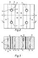
- Figure 2 shows a plan view of a core of bricks surrounding the four boiling tubes 11.
- Figure 2 shows one course of heat storing bricks and, in the embodiment shown, there are sixteen bricks in each course, there being three courses of bricks in all making forty-eight bricks in the entire core.
- Figure 3 being a section along the lines X-X in Figure 2 and Figure 4 being an exploded view of the bricks, two different shapes of brick are used.
- the boiling tubes are arranged bricks 30 of a first shape having semi-circular section, vertical channels 32 formed therein such that two bricks 30 are able to surround a single boiling tube 11. Additionally, the shaped bricks 30 includes horizontal channels 31 which define with plain, cuboidal bricks 35 heating element channels 36. Into which elongate sheathed heating elements 40 can be slid. One such element 40 is shown in a channel 36 in Figure 3.
- a heating element 40 is shown in more detail in Figures 5 and 6, the element 40 being of the sheathed type and being of elongate U-shape. As can be seen in Figure 3, the dimensions of the element channel 36 are such that the sheath of the element makes physical contact with curves of the channel 36 to provide enhanced heat transfer from the element to adjacent bricks. Legs of the U-shape element 40 are held together remote from the base of the U-shape by a mounting plate 41. In assembling a boiler 10, each heating element 40 is slid into a respective heating element channel 36 in the core, having first passed through a front, slotted insulation slab against which the mounting plate 41 lies adjacent in its final position.
- This arrangement has the advantage that electrical connections 42 through which power is supplied to each heating element 40 are insulated from the main heat of the core.
- the front insulation slab of the boiler 10 includes a number of elongate slots for engagement by the heating elements 40 corresponding to the number of heating elements 40 in the boiler 10 and at positions corresponding to the heating element channels 36 in the core. Wiring connections to the heating elements 40 are arranged conventionally and will therefore not be described in detail.
- the material of the heat storing bricks 30 and 35 may be the same, for example magnetite or magnesite or a mixture of the two, magnesite having a higher thermal conductivity than magnetite which can be advantageous in transferring heat stored in the core more rapidly to the boiling tubes 11. It is also possible and can be advantageous for particular boiler demands to form the shaped bricks 30 of a material having higher thermal conductivity than the plain bricks 35. In the configuration described, it is the shaped bricks 30 which lie against the boiling tubes and an increase in thermal conductivity of the shaped bricks 30 results in easier passage of heat to the boiling tubes 11. Where the bricks are made of a mixture of magnetite and magnesite, an increase in thermal conductivity can be achieved by increasing the proportion of magnesite in the bricks.
- Forming the two sorts of bricks of different compositions is economically sensible since magnesite is significantly more expensive than magnetite, the materials having similar heat storing capacities but different thermal conductivities.
- a further advantage of having the shaped bricks 30 with a higher thermal conductivity is that it provides a better direct conduction path from the elements 40 to the boiling tubes 11 should it be necessary to boost the core temperature while heat is actually being drawn from the core in order to provide steam for the heat exchanger 13 to heat the secondary circuit 14. Efficiency of such an operation is thus increased.
- the number and type of bricks 30 and 35 employed allows filling of a boiler casing to be achieved from the front of the casing.
- the core is assembled by first placing the shaped bricks 30 of a particular course around the boiling tubes 11, thereby leaving a space the width of two plain bricks 35 between the shaped bricks and a space the width of one plain brick 35 between respective shaped bricks 30 and the casing side walls. This means that the respective course of bricks can be completed simply by sliding in plain bricks 35 from the front.
- the front insulation slab is placed in front of the core and the elements 40 are simply slid through the front insulation slab and between the bricks in respective element channels 36.
- assembly is achieved entirely from the front and servicing of elements, should there be a failure, is likewise achieved through the front of the casing. This enables the boiler to be fitted under a work surface and yet be serviceable.
- Equipment above the core such as the header tank, heat exchanger and flow heater are also arranged to be accessible from the front.
- These protective sheets have an additional advantage that, at high temperatures the sheets tend to bow and thus force inwardly the bricks of the core with which they are in contact. This has an effect of improving physical contact between the shaped bricks and the boiling tubes and also the bricks surrounding the heating elements 40.
- An additional possibility is to provide a thin sheet of metal, for example stainless steel, extending vertically from front to rear of the core. This sheet acts initially as a shim and also bows at high temperatures to enhance the effect described above with the protective side sheets.
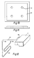
- Figure 8 shows the stepped profiles 56 of the side insulation slabs 53 and 54 and that the stepped arrangement continues to the top of the side insulation slabs 53, 54 to mate with stepped profile in top insulation 57.
- Figure 9 shows stepped mating of top and rear insulations 57 and 50 respectively and the mating of front insulation 55 with the top insulation 57.
- Figures 10 and 11 show the base insulation slab 60 having a peripherally stepped profile shown in Figure 11.
- Four holes 61 are provided for allowing the base insulation slab 60 to slide over the boiling tubes 11 during assembly.
- An advantage of this embodiment of the invention is that installation and maintenance of the boiler can be achieved from the front of the boiler.
- Installation can be effected by plumbing in the boiler to the secondary circuit, which may be in existence already or may be a new system, before the core is built in the casing and then building the core around the boiling tubes and in the remainder of the casing space from the front of the casing.
- the elements are then inserted from the front, after the front insulation is in place, and the casing is then closed for the front cover. Should an element need to be replaced, the front cover is removed, the non-functioning element disconnected and slid out and a replacement element slid in and connected.
- the flow heater is arranged so that its element can be replaced from the front also.
- the insulation profiles minimise heat losses at corners.
- the capillary bleed from the heat exchanger to the header tank allows convenient flushing of air when use of the boiler is started in a simple fashion and with negligible subsequent steam loss.
- Providing the header tank with a capacity substantially larger than the capacity of the primary heating circuit means that topping up of the header tank can be infrequent, it being desirable to provide for topping up during an annual maintenance inspection of the boiler.
- Fig. 13 which shows an alternative pipework layout for a boiler, the pipework includes boiling tubes (64), a heat exchanger (66) and an auxiliary flow heater (68).
- a return pipe (70) extends from the primary heating circuit to the header tank (72). The top of the return pipe is above the water level in the header tank at all times so that water cannot pass from the header tank down the return pipe (70).
- the motor valve (74) is closed to prevent water entering the primary heating circuit from the header tank (72) and the solenoid valve (76) between the heat exchanger and the header tank (72) is also closed.
- Pressure within the primary heating circuit then forces the water/steam in the primary circuit up the return pipe (70) and into the header tank (72). No water from the header tank can pass down the return pipe (70) since the upper end of the pipe is above the water level in the header tank (72).
- the header tank (72) includes a sensor (78) to determine the water level in the tank (72) and hence when additional water should be added via the inlet (80). When the water level in the header tank (72) has fallen below a predetermined level, the sensor (78) is triggered and a light illuminates on the control panel of the boiler appliance.
- the header tank is made of plastics material which enables it to withstand changes in internal pressure and temperature by virtue of its suitable properties. Further, the heat exchanger is more efficient if it is made from copper rather than steel, and water can be drained from the heat exchanger more easily if the exchanger is angled slightly with the drain pipe (82) extending from its lower end.
Landscapes
- Engineering & Computer Science (AREA)
- Thermal Sciences (AREA)
- General Engineering & Computer Science (AREA)
- Mechanical Engineering (AREA)
- Physics & Mathematics (AREA)
- Sustainable Energy (AREA)
- Life Sciences & Earth Sciences (AREA)
- Sustainable Development (AREA)
- Chemical & Material Sciences (AREA)
- Combustion & Propulsion (AREA)
- Heat-Pump Type And Storage Water Heaters (AREA)
- Control Of Steam Boilers And Waste-Gas Boilers (AREA)
- Heat-Exchange Devices With Radiators And Conduit Assemblies (AREA)
- Central Heating Systems (AREA)
Abstract
Description
- The invention relates to boilers in which water is heated by electricity, through the medium of a core of material capable of storing heat, the core being heated by electrically powered heating elements and heat from the core being transferred to a secondary circuit in which a fluid, commonly water, is circulated, as in the case of a domestic central heating or hot water system. It is envisaged that such electrically heated boilers be used in place of gas, oil or solid fuel boilers which also heat fluid secondary circuit in a way which is familiar.
- Electric boilers exist which include a core and elements as referred to above, and in which transfer of heat from the core to the secondary circuit is achieved using air as the heat transfer medium. Thus air is heated by the core and the heated air passes over a heat exchanger through which water in the secondary circuit passes. A more recent approach to an electric storage boiler is to utilise steam as the medium for transferring heat from the store to the secondary circuit. The general arrangement which has been proposed has a core of material capable of storing heat, electrically heated element means in the core, a primary heating circuit, in which water is supplied to the base of boiling tubes which pass steam upwards through the core to a heat exchanger, from which condensed water is returned to the base of the boiling tubes, losses being made up from a header tank or similar arrangement, and a secondary heating circuit portion which passes through the heat exchanger and which is connected, in use, to a secondary heating circuit in a conventional way, the secondary heating circuit including radiators and/or a coil for heating water in a domestic hot water cylinder. Such an electric boiler will be referred to hereinafter as "an electric boiler of the kind described", and is envisaged as a substitute for a gas, oil or solid fuel boiler.
- Electric boilers as defined in the pre-characterising part of
claim 1 are known from DE-A-1812340 and FR-A-1434485. - A practical problem with electric boilers of the kind described is arranging for manageable installation and servicing, for example replacement of heating elements which may fail from time to time. In order to provide a satisfactorily large heat store, a substantial weight of heat storing bricks is necessary and it is desirable to be able to install and service the boiler from a single direction, preferably from the front so that the boiler can be placed, if desired, under a working surface.
- According to the invention, there is provided an electric boiler in which a liquid is heated by means of a heat storing core, the core consisting of a multiplicity of first heat storing bricks and being heated by electrically powered heating elements, and heat from the core is transferred to a primary heating circuit in which the liquid is circulated, the primary heating circuit comprising a plurality of boiling tubes extending substantially vertically in an insulated casing surrounding the core, the casing having a front face, a rear face and two side faces, said boiling tubes being arranged in at least one row extending essentially parallel to said front face, said first bricks lying against the boiling tubes and having side face profiles formed to provide channels for accepting part of a boiling tube whereby a combination of such first bricks surrounds a length of boiling tubes, characterised in that
said front face is openable to allow installation of the core and access thereto, and
between the side faces of the casing and the first bricks as well as between the first bricks of two adjacent tubes of the same row are arranged second bricks which do not engage any parts of the boiling tubes. - The bricks in an assembled core preferably define channels extending from front to rear of the boiler, the heating elements being elongate and located in the core by sliding into the channels from the front of the core. Each element is preferably U-shaped. The cross-sectional profile of the element channels and the cross-section of the heating elements are preferably such that contact is achieved between a portion of the external surface of each element and the adjacent bricks.
- The bricks which lie against the boiling tubes may be of a different profile from the second bricks. The second bricks preferably have planar faces, and each brick which lies against the boiling tubes preferably includes not only the boiling tube portion accepting channel but groove means extending, in use, in a direction from front to back of the core, which groove means defining with a planar face of a second brick at least one channel for accepting an element. Each groove means preferably has two parallel grooves such that each pair of bricks which includes a second brick defines two element channels.
- The core preferably comprises a plurality of brick and boiling tube units, each unit comprising a length of boiling tube, a pair of bricks lying against and surrounding, between them, the length of boiling tube, and a pair of second bricks, each lying outside and against a respective one of the boiling tube contacting bricks to define at least one element channel on each side of the boiling tube.
- The larger the boiler capacity, the larger the number of brick and boiler tube units, but a preferred embodiment envisages a boiler tube to be three brick courses high, and with four boiling tubes, a total of forty-eight bricks. With such a height, a boiler with two boiling tubes would have twenty-four bricks, and a boiler with six boiling tubes would have seventy-two bricks.
- The insulated casing preferably has a front insulation layer including slots through which the elements pass whereby contacts for connecting each element to an electrical supply lie on the side of the insulation remote from the core, in use.
- Metal sheets, for example of stainless steel, may be placed within and to cover the inner surfaces of the insulation on the side walls, base and top of the casing. A further metal sheet, again of stainless steel for example, may be placed in a vertical plane adjacent walls of the further bricks.
- Preferably a header tank provided for the boiler has a capacity substantially larger than, and preferably at least double the capacity of the primary heating circuit.
- Preferably the composition of bricks contacting a boiling tube is different from the composition of bricks not contacting a boiling tube, and the thermal conductivity of bricks contacting a boiling tube is greater than the thermal conductivity of bricks not contacting a boiling tube.
- The composition of the bricks lying between elements may be magnetiteand the composition of bricks between an element and a boiling tube may be a mixture of magnetite and magnesite. The proportion of magnetite to magnesite may be varied from boiler to boiler to achieve particular storage and heat release characteristics.
- Preferably the edge profiles of insulation layers around the core are such that there is a stepped edge profile on at least one of and preferably both insulation layers abutting at right angles.
- By way of example, one embodiment of an electric boiler according to the invention will now be described with reference to the accompanying drawings, in which:-
- Figure 1 is a schematic illustration of the pipework layout of a boiler;
- Figure 2 is a plan view of a course of core bricks in the boiler of Figure 1 having four boiling tubes;
- Figure 3 is a sectional view along the lines X-X in Figure 2, and showing one element in position for the sake of example;
- Figure 4 is an exploded view of the course of bricks of Figures 2 and 3;
- Figure 5 is a side view of a heating element;
- Figure 6 is a plan view of the heating element of Figure 5;
- Figure 7 is a plan view of side, front and rear insulation of the casing;
- Figure 8 is a front view of insulation of the casing, but without base and front insulation;
- Figure 9 is a side view of top, front and rear insulation;
- Figure 10 is a plan view of base insulation;
- Figure 11 is an end view of the base insulation of Figure 10;
- Figure 12 is a view of a header tank and condensing vent as incorporated in another boiler according to the invention; and
- Figure 13 is a schematic illustration of an alternative pipework layout for a boiler according to the invention.
- Figure 1 shows a schematic layout of pipework in an
electric boiler 10 according to the invention. A primary heating circuit has fourboiling tubes 11 surrounded in an assembled boiler by a core of heat storing bricks (not shown in Figure 1). Vaporizable liquid, preferably demineralised water, is fed to the base of theboiling tubes 11 viapipes 12 and water in the boiling tubes is turned to steam by heat in the core, the steam rising from the boiling tubes to aheat exchanger 13 through which liquid in asecondary heating circuit 14 flows. Steam from the boiling tubes condenses in theheat exchanger 13 while giving up its heat to thesecondary circuit 14, condensed steam returning viapipe 15 and motorisedvalve 16 to thepipes 12. Themotorised valve 16 is opened to allow the primary heating circuit to operate if there is a demand for heat from thesecondary heating circuit 14. Themotorised valve 16 can be controlled, for example, by a room thermostat or other suitable means to indicate a need for heat. - To insure an adequate level of fluid in the primary heating circuit, a
header tank 17 having a capacity approximately twice that of the primary heating circuit is able to feed liquid via themotorised valve 16 to thepipes 12.Non-return valve 18 is provided to allow water to return to theheader tank 17 when heat is not required from the boiler and themotorised valve 16 is therefore closed. Adrain cock 20 is provided to allow theheader tank 17 to be drained. - When the
motorised valve 16 is first opened after a spell of the primary heating circuit being closed, air will be present in the chamber of theheat exchanger 13 and it is necessary to allow that air to be flushed out of the heat exchanger. To this end, a capillary bleed is provided from theheat exchanger 13 into theheader tank 17, anon-return valve 22 being fitted to prevent return of fluid from theheader tank 17 to theheat exchanger 13. Air present in theheat exchanger 13 can be flushed through thecapillary 21, subsequent loss of steam from the heat exchanger due to the permanent presence of thecapillary 21 being negligible when the system if fully operational. It will be appreciated that any steam passing through thecapillary 21 will have condensed during passage through the capillary lying in liquid in theheader tank 17. - A
flow heater 23 is provided in the secondary heating circuit to provide direct heating in the secondary heating circuit if necessary. A control system provides apportionment of heat supplied to the secondary heating circuit from theflow heater 23 or theheat exchanger 13. The presence of theflow heater 23 and the control system therefore is the subject of a co-pending Patent application of today's date. - Figure 12 shows the
header tank 17 in isolation. In order to allow liquid to be drawn from theheader tank 17 , venting to atmosphere must take place. Venting takes place via atube coupling 130 to which is connected asmall bore tube 131. A preferred bore for thetube 131 is 3mm but it will be appreciated that other small bore tubes may be used, typically in the range 1mm to 5mm although other bores may be appropriate in certain circumstances. Thetube 131 runs horizontally in an upper portion and bends downwards atpoint 132. In an assembled boiler, thetube 131 would exit from the boiler casing on the header tank side of thebend 132. From thebend 132, thetube 131 extends downwards and into alarger bore tube 133, in this embodiment of 8mm bore. The larger bore tube could be of a different bore from 8mm, for example within the range 5mm to 10mm although other bores could be used. Thetube 131 extends to the lowest point of thelarger bore tube 133, thelarger bore tube 133 then rising in a S configuration to anoutlet 134. In this way, there is a long condensation path for vapour trying to leave thetube 133, condensed vapour forming a liquid pool rising from the lowest point of thetube 133. - When water is drawn from the header tank to feed the primary heating circuit, when the boiler is in use, liquid from the bottom of the
larger bore tube 133 is drawn back to the header tank through thesmall bore tube 131. The smaller the volume within thesmall bore tube 131, the more liquid will be returned to the header tank for a given displacement of water from it. - Throughout this specification, it will be appreciated that water is not the only liquid which could be used in the primary heating circuit although it is the preferred vaporizable liquid.
- The advantage of this embodiment of a header tank according to the invention is that evaporation losses from the header tank are minimised, thereby reducing the frequency at which the header tank must be refilled.
- Figure 2 shows a plan view of a core of bricks surrounding the four boiling
tubes 11. Figure 2 shows one course of heat storing bricks and, in the embodiment shown, there are sixteen bricks in each course, there being three courses of bricks in all making forty-eight bricks in the entire core. - As can be seen in Figures 2, 3 and 4, Figure 3 being a section along the lines X-X in Figure 2 and Figure 4 being an exploded view of the bricks, two different shapes of brick are used.
- Around the boiling tubes are arranged
bricks 30 of a first shape having semi-circular section,vertical channels 32 formed therein such that twobricks 30 are able to surround asingle boiling tube 11. Additionally, the shapedbricks 30 includeshorizontal channels 31 which define with plain,cuboidal bricks 35heating element channels 36. Into which elongate sheathedheating elements 40 can be slid. Onesuch element 40 is shown in achannel 36 in Figure 3. - A
heating element 40 is shown in more detail in Figures 5 and 6, theelement 40 being of the sheathed type and being of elongate U-shape. As can be seen in Figure 3, the dimensions of theelement channel 36 are such that the sheath of the element makes physical contact with curves of thechannel 36 to provide enhanced heat transfer from the element to adjacent bricks. Legs of theU-shape element 40 are held together remote from the base of the U-shape by a mountingplate 41. In assembling aboiler 10, eachheating element 40 is slid into a respectiveheating element channel 36 in the core, having first passed through a front, slotted insulation slab against which the mountingplate 41 lies adjacent in its final position. This arrangement has the advantage thatelectrical connections 42 through which power is supplied to eachheating element 40 are insulated from the main heat of the core. There is no view of the front insulation slab of theboiler 10 but it will be appreciated that the front insulation slab includes a number of elongate slots for engagement by theheating elements 40 corresponding to the number ofheating elements 40 in theboiler 10 and at positions corresponding to theheating element channels 36 in the core. Wiring connections to theheating elements 40 are arranged conventionally and will therefore not be described in detail. - The material of the
heat storing bricks tubes 11. It is also possible and can be advantageous for particular boiler demands to form the shapedbricks 30 of a material having higher thermal conductivity than theplain bricks 35. In the configuration described, it is the shapedbricks 30 which lie against the boiling tubes and an increase in thermal conductivity of the shapedbricks 30 results in easier passage of heat to the boilingtubes 11. Where the bricks are made of a mixture of magnetite and magnesite, an increase in thermal conductivity can be achieved by increasing the proportion of magnesite in the bricks. Forming the two sorts of bricks of different compositions is economically sensible since magnesite is significantly more expensive than magnetite, the materials having similar heat storing capacities but different thermal conductivities. A further advantage of having the shapedbricks 30 with a higher thermal conductivity is that it provides a better direct conduction path from theelements 40 to the boilingtubes 11 should it be necessary to boost the core temperature while heat is actually being drawn from the core in order to provide steam for theheat exchanger 13 to heat thesecondary circuit 14. Efficiency of such an operation is thus increased. - The number and type of
bricks bricks 30 of a particular course around the boilingtubes 11, thereby leaving a space the width of twoplain bricks 35 between the shaped bricks and a space the width of oneplain brick 35 between respective shapedbricks 30 and the casing side walls. This means that the respective course of bricks can be completed simply by sliding inplain bricks 35 from the front. In the particular embodiment shown, there are three courses of bricks and each course can be built up in exactly the same way, placing of the shaped bricks in position being straightforward in view of the amount of space on either side and positioning of the plain bricks requiring no turning, simply sliding in a front to rear direction. - Once the core has been assembled, the front insulation slab is placed in front of the core and the
elements 40 are simply slid through the front insulation slab and between the bricks inrespective element channels 36. Thus, assembly is achieved entirely from the front and servicing of elements, should there be a failure, is likewise achieved through the front of the casing. This enables the boiler to be fitted under a work surface and yet be serviceable. - Equipment above the core such as the header tank, heat exchanger and flow heater are also arranged to be accessible from the front.
- It will be appreciated that with a core of bricks heated to temperatures of 750°C or higher, for example 850°C, and with it being desirable to minimise heat loss from the casing since the boiler is designed to supply a secondary heating circuit, care must be taken to maximise the efficiency of the casing insulation. Calcium silicate is preferably used for the base insulation, and microporous insulation is preferably used for the other areas. This material has, however, to be treated carefully, and without protection, there is a risk of damage from abrasion when sliding in bricks during assembly of the core. Accordingly, thin sheets of metal, preferably stainless steel, are used to protect the base, side and top insulation in the casing. These protective sheets, particularly against the side insulations, have an additional advantage that, at high temperatures the sheets tend to bow and thus force inwardly the bricks of the core with which they are in contact. This has an effect of improving physical contact between the shaped bricks and the boiling tubes and also the bricks surrounding the
heating elements 40. An additional possibility is to provide a thin sheet of metal, for example stainless steel, extending vertically from front to rear of the core. This sheet acts initially as a shim and also bows at high temperatures to enhance the effect described above with the protective side sheets. - While heat losses directly through the wall insulation can be minimised, a consistent problem arises where slabs of insulation meet at a right angled corner. To minimise corner losses, the insulation slabs have been designed as shown in Figures 7, 8, 9 and 10 to provide at every corner at least one step contact so that there is no direct heat leakage path from the core to outside the insulation. This is achieved by stepping the insulation slabs at their periphery, the slabs being formed either in one piece with a step or in two pieces, one piece being of smaller dimensions than the other. With reference to Figure 7 (a plan view),
rear insulation 50 has stepped side edge profiles 51 which mate with stepped side edge profiles 52 ofside insulation panel Front insulation slab 55 has plain edges and locates in a recess formed bysteps 56 in theside insulation slabs - Figure 8 shows the stepped profiles 56 of the
side insulation slabs side insulation slabs top insulation 57. - Figure 9 shows stepped mating of top and
rear insulations front insulation 55 with thetop insulation 57. - Figures 10 and 11 show the base insulation slab 60 having a peripherally stepped profile shown in Figure 11. Four
holes 61 are provided for allowing the base insulation slab 60 to slide over the boilingtubes 11 during assembly. - An advantage of this embodiment of the invention is that installation and maintenance of the boiler can be achieved from the front of the boiler. Installation can be effected by plumbing in the boiler to the secondary circuit, which may be in existence already or may be a new system, before the core is built in the casing and then building the core around the boiling tubes and in the remainder of the casing space from the front of the casing. The elements are then inserted from the front, after the front insulation is in place, and the casing is then closed for the front cover. Should an element need to be replaced, the front cover is removed, the non-functioning element disconnected and slid out and a replacement element slid in and connected. The flow heater is arranged so that its element can be replaced from the front also. The insulation profiles minimise heat losses at corners. The capillary bleed from the heat exchanger to the header tank allows convenient flushing of air when use of the boiler is started in a simple fashion and with negligible subsequent steam loss. Providing the header tank with a capacity substantially larger than the capacity of the primary heating circuit means that topping up of the header tank can be infrequent, it being desirable to provide for topping up during an annual maintenance inspection of the boiler.
With specific reference to Fig. 13 which shows an alternative pipework layout for a boiler, the pipework includes boiling tubes (64), a heat exchanger (66) and an auxiliary flow heater (68). A return pipe (70) extends from the primary heating circuit to the header tank (72). The top of the return pipe is above the water level in the header tank at all times so that water cannot pass from the header tank down the return pipe (70). - When the secondary heating circuit is switched off, it is advantageous if there is no water or steam left in the primary heating circuit since if there were, this would consume energy from the core due to continual evaporation and condensation of the water/steam. Accordingly, in order to remove the water and steam from the primary heating circuit the motor valve (74) is closed to prevent water entering the primary heating circuit from the header tank (72) and the solenoid valve (76) between the heat exchanger and the header tank (72) is also closed. Pressure within the primary heating circuit then forces the water/steam in the primary circuit up the return pipe (70) and into the header tank (72). No water from the header tank can pass down the return pipe (70) since the upper end of the pipe is above the water level in the header tank (72).
- The header tank (72) includes a sensor (78) to determine the water level in the tank (72) and hence when additional water should be added via the inlet (80). When the water level in the header tank (72) has fallen below a predetermined level, the sensor (78) is triggered and a light illuminates on the control panel of the boiler appliance.
- In a preferred embodiment of the invention the header tank is made of plastics material which enables it to withstand changes in internal pressure and temperature by virtue of its suitable properties. Further, the heat exchanger is more efficient if it is made from copper rather than steel, and water can be drained from the heat exchanger more easily if the exchanger is angled slightly with the drain pipe (82) extending from its lower end.
Claims (14)
- An electric boiler in which a liquid is heated by means of a heat storing core, the core consisting of a multiplicity of first heat storing bricks (30) and being heated by electrically powered heating elements (40), and heat from the core is transferred to a primary heating circuit in which the liquid is circulated, the primary heating circuit comprising a plurality of boiling tubes (11) extending substantially vertically in an insulated casing surrounding the core, the casing having a front face, a rear face and two side faces, said boiling tubes being arranged in at least one row extending essentially parallel to said front face, said first bricks (30) lying against the boiling tubes (11) and having side face profiles formed to provide channels (31) for accepting part of a boiling tube (11) whereby a combination of such first bricks (30) surrounds a length of boiling tubes (11), characterised in that
said front face is openable to allow installation of the core and access thereto, and
between the side faces of the casing and the first bricks (30) as well as between the first bricks (30) of two adjacent tubes of the same row are arranged second bricks (35) which do not engage any parts of the boiling tubes (11). - A boiler as claimed in claim 1, wherein the bricks (30,35) in an assembled core define channels (36) extending from front to rear of the boiler for receiving the heating elements (40), the heating elements (40) being elongate and located in the core by sliding into the channels (36) from the front of the core.
- A boiler as claimed in claim 2, wherein the cross-sectional profile of the element channels (36) and the cross-section of the heating elements (40) are such that contact is achieved between a portion of the external surface of each element (40) and the adjacent bricks (30, 35).
- A boiler as claimed in any preceding claim, wherein the first bricks (30) which lie against the boiling tubes (11) are of a different profile to that of the second bricks (35).
- A boiler as claimed in claim 4, wherein the second bricks (35) have planar faces, and each brick (30) which lies against the boiling tubes (11) includes not only the boiling tube portion accepting channel (31) but groove means (32) extending, in use, in a direction from front to back of the core, which groove means defining with a planar face of a second brick (35) at least one channel (36) for accepting an element (40).
- A boiler as claimed in claim 5, wherein each groove means (32) has two parallel grooves such that each pair of bricks (30,35) which includes a second brick (35) defines two element channels (36).
- A boiler as claimed in any preceding claim, wherein the core comprises a plurality of brick and boiling tube units, each unit comprising a length of boiling tube (11), a pair of bricks (30) lying against and surrounding, between them, the length of boiling tube (11), and a pair of second bricks (35), each lying outside and against a respective one of the boiling tube contacting bricks (30) to define at least one element channel (36) on each side of the boiling tube (11).
- A boiler as claimed in any preceding claim, wherein the boiler includes two boiling tubes (11) and twenty four bricks (30,35), or four boiling tubes (11) and forty eight bricks (30,35) or six boiling tubes (11) and seventy two bricks (30,35).
- A boiler as claimed in any preceding claim, wherein metal sheets are placed within and cover the inner surfaces of the insulation on the side walls, base and top of the casing.
- A boiler as claimed in any preceding claim, wherein a header tank (17) provided for the boiler has a capacity at least double the capacity of the primary heating circuit.
- A boiler as claimed in any preceding claim, wherein the thermal conductivity of bricks (30) contacting a boiling tube (11) is greater than the thermal conductivity of bricks (35) not contacting a boiling tube (11).
- A boiler as claimed in claim 11, wherein the composition of bricks (35) lying between elements (40) is magnetite and the composition of bricks (30) between an element (40) and a boiling tube (11) is a mixture of magnetite and magnesite.
- A boiler as claimed in any preceding claim, wherein the insulated casing includes a plurality of insulating layers (50-57).
- A boiler as claimed in claim 13, wherein the edge profiles the insulation layers (50-57) are such that there is a stepped edge profile on at least one of the insulation layers abutting at right angles.
Applications Claiming Priority (9)
| Application Number | Priority Date | Filing Date | Title |
|---|---|---|---|
| GB888828421A GB8828421D0 (en) | 1988-12-06 | 1988-12-06 | Electric boiler |
| GB888828422A GB8828422D0 (en) | 1988-12-06 | 1988-12-06 | Improvements in boilers |
| GB8828422 | 1988-12-06 | ||
| GB8828421 | 1988-12-06 | ||
| GB8901281 | 1989-01-20 | ||
| GB898901281A GB8901281D0 (en) | 1989-01-20 | 1989-01-20 | Improvements in or relating to boilers |
| GB8922306 | 1989-10-04 | ||
| GB898922306A GB8922306D0 (en) | 1989-10-04 | 1989-10-04 | Improvements in or relating to boilers and controls therefor |
| PCT/GB1989/001459 WO1990006473A2 (en) | 1988-12-06 | 1989-12-06 | Electrical heat storage boiler |
Publications (2)
| Publication Number | Publication Date |
|---|---|
| EP0447438A1 EP0447438A1 (en) | 1991-09-25 |
| EP0447438B1 true EP0447438B1 (en) | 1995-03-29 |
Family
ID=27450225
Family Applications (2)
| Application Number | Title | Priority Date | Filing Date |
|---|---|---|---|
| EP19900900241 Withdrawn EP0533658A1 (en) | 1988-12-06 | 1989-12-06 | An electric boiler and controls therefor |
| EP90900240A Expired - Lifetime EP0447438B1 (en) | 1988-12-06 | 1989-12-06 | Electrical heat storage boiler |
Family Applications Before (1)
| Application Number | Title | Priority Date | Filing Date |
|---|---|---|---|
| EP19900900241 Withdrawn EP0533658A1 (en) | 1988-12-06 | 1989-12-06 | An electric boiler and controls therefor |
Country Status (4)
| Country | Link |
|---|---|
| EP (2) | EP0533658A1 (en) |
| DE (1) | DE68921988T2 (en) |
| ES (1) | ES2070310T3 (en) |
| WO (2) | WO1990006473A2 (en) |
Families Citing this family (1)
| Publication number | Priority date | Publication date | Assignee | Title |
|---|---|---|---|---|
| SE509732C2 (en) * | 1996-06-18 | 1999-03-01 | Tsp Medical Ab | Steam generator with controlled supply and removal of water |
Family Cites Families (9)
| Publication number | Priority date | Publication date | Assignee | Title |
|---|---|---|---|---|
| AT234236B (en) * | 1962-12-27 | 1964-06-25 | Veitscher Magnesitwerke Ag | Electric storage heater with several resistance heating elements to be fed from a three-phase network |
| BE657497A (en) * | 1964-12-23 | 1965-06-23 | Acec | Control device for the heating resistance of a storage stove |
| FR1434485A (en) * | 1965-03-24 | 1966-04-08 | Witte Haustechnik Gmbh | Periodically operated steam generator, electrically heated and fitted with a heat accumulator |
| DE1579864A1 (en) * | 1965-09-02 | 1970-08-27 | Elektrowaerme Inst Essen E V | Electric storage heating |
| DE1812340A1 (en) * | 1968-12-03 | 1970-06-25 | Zenkner Dr Ing Kurt | Night storage heater |
| GB1296992A (en) * | 1969-03-20 | 1972-11-22 | ||
| GB1261649A (en) * | 1969-06-10 | 1972-01-26 | Potterton Internat Ltd | Control means for electrical storage heaters |
| GB1394745A (en) * | 1972-06-13 | 1975-05-21 | Potterton Int Ltd | Storage heaters |
| CH635187A5 (en) * | 1980-04-15 | 1983-03-15 | Battelle Memorial Institute | HEATING APPLIANCE. |
-
1989
- 1989-12-06 WO PCT/GB1989/001459 patent/WO1990006473A2/en not_active Ceased
- 1989-12-06 WO PCT/GB1989/001458 patent/WO1990006477A2/en not_active Ceased
- 1989-12-06 DE DE68921988T patent/DE68921988T2/en not_active Expired - Fee Related
- 1989-12-06 EP EP19900900241 patent/EP0533658A1/en not_active Withdrawn
- 1989-12-06 ES ES90900240T patent/ES2070310T3/en not_active Expired - Lifetime
- 1989-12-06 EP EP90900240A patent/EP0447438B1/en not_active Expired - Lifetime
Also Published As
| Publication number | Publication date |
|---|---|
| WO1990006473A3 (en) | 1990-08-23 |
| EP0447438A1 (en) | 1991-09-25 |
| ES2070310T3 (en) | 1995-06-01 |
| EP0533658A1 (en) | 1993-03-31 |
| DE68921988T2 (en) | 1995-08-03 |
| WO1990006477A3 (en) | 1990-08-23 |
| WO1990006477A2 (en) | 1990-06-14 |
| DE68921988D1 (en) | 1995-05-04 |
| WO1990006473A2 (en) | 1990-06-14 |
Similar Documents
| Publication | Publication Date | Title |
|---|---|---|
| US5179259A (en) | Inverted frustum shaped microwave heat exchanger using a microwave source with multiple magnetrons and applications thereof | |
| FI76205B (en) | SYSTEM OVERHEAD ENCLOSURE OAK EN VAERMEVAEXLARE. | |
| US6647932B1 (en) | Compact boiler with tankless heater for providing heat and domestic hot water | |
| KR102751199B1 (en) | Thermal battery with internally heated phase change material | |
| CA2001505C (en) | Pipe apparatus in heat accumulator | |
| US5193138A (en) | Off-peak thermal storage system providing a plurality of selected temperature outlets | |
| US5265444A (en) | Inverted frustum shaped microwave heat exchanger using a microwave source with multiple magnetrons and applications thereof | |
| US6957014B2 (en) | Liquid heater | |
| US4513585A (en) | Hot water system using a compressor | |
| JPH01163555A (en) | Hot water supplier | |
| KR101005610B1 (en) | Heat storage tank using solar heat | |
| WO1990006473A2 (en) | Electrical heat storage boiler | |
| AU2009201129A1 (en) | Liquid Heater | |
| JPS5950903B2 (en) | Heat exchanger | |
| GB2241569A (en) | Boilers | |
| KR101844187B1 (en) | Boiler with improved heat recovery | |
| GB2241568A (en) | Boilers | |
| US4655042A (en) | Method and apparatus for improving the operation of a hot water heater | |
| EP4703649A1 (en) | Non-pressurized thermic accumulator with freon coil and wall comprising said thermic accumulator | |
| RU2006781C1 (en) | Water heating device | |
| RU2045699C1 (en) | Self-contained boiler plant for steam heating systems | |
| CA1189839A (en) | Heat exchange unit | |
| CN2679577Y (en) | Instant heating electric water heater | |
| GB2312493A (en) | Boiler for space heating and domestic hot water | |
| HK40044968B (en) | Internally heated phase change material heat batteries |
Legal Events
| Date | Code | Title | Description |
|---|---|---|---|
| PUAI | Public reference made under article 153(3) epc to a published international application that has entered the european phase |
Free format text: ORIGINAL CODE: 0009012 |
|
| 17P | Request for examination filed |
Effective date: 19910606 |
|
| AK | Designated contracting states |
Kind code of ref document: A1 Designated state(s): BE DE ES FR GB NL |
|
| 17Q | First examination report despatched |
Effective date: 19931006 |
|
| RAP1 | Party data changed (applicant data changed or rights of an application transferred) |
Owner name: DIMPLEX (UK) LIMITED |
|
| GRAA | (expected) grant |
Free format text: ORIGINAL CODE: 0009210 |
|
| AK | Designated contracting states |
Kind code of ref document: B1 Designated state(s): BE DE ES FR GB NL |
|
| PG25 | Lapsed in a contracting state [announced via postgrant information from national office to epo] |
Ref country code: NL Free format text: LAPSE BECAUSE OF NON-PAYMENT OF DUE FEES Effective date: 19950329 Ref country code: FR Effective date: 19950329 |
|
| REF | Corresponds to: |
Ref document number: 68921988 Country of ref document: DE Date of ref document: 19950504 |
|
| REG | Reference to a national code |
Ref country code: ES Ref legal event code: FG2A Ref document number: 2070310 Country of ref document: ES Kind code of ref document: T3 |
|
| EN | Fr: translation not filed | ||
| NLV1 | Nl: lapsed or annulled due to failure to fulfill the requirements of art. 29p and 29m of the patents act | ||
| PGFP | Annual fee paid to national office [announced via postgrant information from national office to epo] |
Ref country code: GB Payment date: 19951127 Year of fee payment: 7 |
|
| PGFP | Annual fee paid to national office [announced via postgrant information from national office to epo] |
Ref country code: DE Payment date: 19951214 Year of fee payment: 7 |
|
| PGFP | Annual fee paid to national office [announced via postgrant information from national office to epo] |
Ref country code: ES Payment date: 19951219 Year of fee payment: 7 |
|
| PGFP | Annual fee paid to national office [announced via postgrant information from national office to epo] |
Ref country code: BE Payment date: 19960109 Year of fee payment: 7 |
|
| PLBE | No opposition filed within time limit |
Free format text: ORIGINAL CODE: 0009261 |
|
| STAA | Information on the status of an ep patent application or granted ep patent |
Free format text: STATUS: NO OPPOSITION FILED WITHIN TIME LIMIT |
|
| 26N | No opposition filed | ||
| PG25 | Lapsed in a contracting state [announced via postgrant information from national office to epo] |
Ref country code: GB Effective date: 19961206 |
|
| PG25 | Lapsed in a contracting state [announced via postgrant information from national office to epo] |
Ref country code: BE Effective date: 19961231 |
|
| BERE | Be: lapsed |
Owner name: DIMPLEX (UK) LTD Effective date: 19961231 |
|
| GBPC | Gb: european patent ceased through non-payment of renewal fee |
Effective date: 19961206 |
|
| PG25 | Lapsed in a contracting state [announced via postgrant information from national office to epo] |
Ref country code: DE Effective date: 19970902 |
|
| PG25 | Lapsed in a contracting state [announced via postgrant information from national office to epo] |
Ref country code: ES Free format text: LAPSE BECAUSE OF NON-PAYMENT OF DUE FEES Effective date: 19971207 |
|
| REG | Reference to a national code |
Ref country code: ES Ref legal event code: FD2A Effective date: 19980113 |