EP0447507B1 - Stylo retractable a double element d'ecriture - Google Patents
Stylo retractable a double element d'ecriture Download PDFInfo
- Publication number
- EP0447507B1 EP0447507B1 EP90913274A EP90913274A EP0447507B1 EP 0447507 B1 EP0447507 B1 EP 0447507B1 EP 90913274 A EP90913274 A EP 90913274A EP 90913274 A EP90913274 A EP 90913274A EP 0447507 B1 EP0447507 B1 EP 0447507B1
- Authority
- EP
- European Patent Office
- Prior art keywords
- cam
- barrel member
- writing instrument
- barrel
- cylindrical cam
- Prior art date
- Legal status (The legal status is an assumption and is not a legal conclusion. Google has not performed a legal analysis and makes no representation as to the accuracy of the status listed.)
- Expired - Lifetime
Links
- 230000009977 dual effect Effects 0.000 title abstract description 5
- 230000013011 mating Effects 0.000 claims description 3
- 230000015572 biosynthetic process Effects 0.000 claims description 2
- 238000005755 formation reaction Methods 0.000 claims description 2
- 230000002093 peripheral effect Effects 0.000 description 6
- 230000000694 effects Effects 0.000 description 3
- 230000000717 retained effect Effects 0.000 description 2
- 229920001169 thermoplastic Polymers 0.000 description 2
- 239000004416 thermosoftening plastic Substances 0.000 description 2
- 238000010276 construction Methods 0.000 description 1
- 230000008878 coupling Effects 0.000 description 1
- 238000010168 coupling process Methods 0.000 description 1
- 238000005859 coupling reaction Methods 0.000 description 1
- 239000000463 material Substances 0.000 description 1
- 239000000203 mixture Substances 0.000 description 1
- 239000002952 polymeric resin Substances 0.000 description 1
- 229920003002 synthetic resin Polymers 0.000 description 1
- 229920001187 thermosetting polymer Polymers 0.000 description 1
Images

Classifications
-
- B—PERFORMING OPERATIONS; TRANSPORTING
- B43—WRITING OR DRAWING IMPLEMENTS; BUREAU ACCESSORIES
- B43K—IMPLEMENTS FOR WRITING OR DRAWING
- B43K21/00—Propelling pencils
-
- B—PERFORMING OPERATIONS; TRANSPORTING
- B43—WRITING OR DRAWING IMPLEMENTS; BUREAU ACCESSORIES
- B43K—IMPLEMENTS FOR WRITING OR DRAWING
- B43K24/00—Mechanisms for selecting, projecting, retracting or locking writing units
- B43K24/10—Mechanisms for selecting, projecting, retracting or locking writing units for selecting, projecting and locking several writing units
- B43K24/14—Mechanisms for selecting, projecting, retracting or locking writing units for selecting, projecting and locking several writing units operated by turning means
- B43K24/146—Mechanisms for selecting, projecting, retracting or locking writing units for selecting, projecting and locking several writing units operated by turning means with cam control
Definitions
- the present invention relates generally to improvements in writing instruments and it relates particularly to a writing instrument according to the first part of claim 1.
- Protract retract dual writing element pens of the twist type are well known and widely employed.
- Such pens conventionally include a pair of manually accessible control components, one being a cylindrical cam and the other a longitudinal guide member and writing element engaging chucks which are restricted to longitudinal movement by the guide member having followers engaging the cam to effect such longitudinal movement of the chucks and writing elements with the relative rotation or twisting of the control components which alternatively effects the advance of a selected one of the writing elements and the withdrawal of the other.
- twist type dual writing element is highly convenient to use but is generally complicated and expensive, requiring a large number of separate parts many of which are costly and a time consuming and laborious assembly calling for highly skilled labor.
- the conventional and known twist type dual element retractable pen is by reason of its complexity and cost unsuitable for use as a disposable or throw-away article.
- a writing instrument having two writing elements is known.
- a tubular cam is utilized together with cam followers and element holders for each writing element and associated supporting structure to provide an instrument which will position one element in the extended position while positioning the second element in the retracted position without the use of springs, will lock each element in its respective position.
- the cam assembly is a separate subassembly from the barrel member and includes axially spaced first and second cam sections which have interfitting tang and recess at their confronting ends and a sleeve member telescope by and retaining the two cam sections in their intercoupled position.
- the subassembly of the sleeve and the two cam parts are inserted into and tightly retained by the pen barrel member. Therefore, this construction requires four parts, i.e. the barrel member, the two cam parts and the retaining sleeve.
- a multiple-insert which has a mechanical press-button-operated insert.
- This pen has a cylindrical holder with top and bottom sections axially inline which can be turned in relation to each other, while a cage accomodates a plunger and the other inserts and is coupled to the lower section.
- a cam mechanism inside the upper section normally holds the both inserts retracted and slides a selected one forward into the writing position when the upper section is rotated.
- the press-button normally protrudes from the upper section, and has a stepped slide extending downwards from it. This acts against the plunger insert when the section is rotated to bring the letter into the writing position, so as to prepare it, ready for writing and marking.
- a principal object of the present invention is the provision of an improved writing instrument.
- Another object of the present invention is the provision of an improved retractable pen.
- Still another object of the present invention is to provide an improved twist type retractable pen.
- a further object of the present invention is to provide an improved multiple element twist type retractable pen in which the individual writing elements are selectively protractable.
- Still a further object of the present invention is to provide an improved multiple writing element retractable pen comprising a minimum of components which are easily and rapidly assembled with little skill and each of which is easily moldable of a thermoplastic polymeric material to provide a rugged, reliable, and inexpensive device of attractive appearance and cheap enough to be disposable or a throw-away or giveaway.
- a retractable multiple writing element pen in accordance with the present invention includes axially coupled upper and lower barrel members, the upper barrel member having integrally formed on its inside face a first cylindrical cam portion having along its bottom a peripherally longitudinally inclined top cam surface.
- a second cam portion has a top face defining a bottom cam surface complementing, parallel to and spaced from the top cam surface to delineate a cylindrical cam track or groove including oppositely axially peripherally inclined cam groove sections.
- the second cam portion telescopes the upper barrel section with an interference fit and a mating longitudinal ridge and groove are formed in the confronting faces of the second cam and upper barrel member to precisely index and orient the top and bottom cam surfaces.
- a guide member having opposite longitudinal channels is rotatably axially positioned in the barrels and a writing element engaging chuck slidably engages each longitudinal channel and includes a transverse follower slidably engaging the cam groove.
- a writing element engages each of the chucks and extends toward the apertured tapered tip of the lower barrel member.
- the lower cam section is integrally formed as a unit with the lower barrel member and the guide member terminates at its top in an enlarged head or knob to facilitate the manual turning of the guide member relative to the barrel to effect the writing element advance and withdrawal movements.
- the improved multiple element retractable pen in addition to the writing elements, per se, includes only five or six individual parts, each of which is molded as a single unit, of a thermoplastic or thermosetting organic polymeric resin composition, the component parts are easily and rapidly assembled, the parts interfitting and indexing formations being integrally formed on the respective components. Moreover, springs and other elements are obviated.
- the resulting writing instrument is rugged, reliable, simple, easily decorated and of attractive appearance and of low final cost permitting its use as a disposable giveaway and throwaway article.
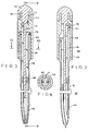
- the improved modified pen is designated by the reference numeral 58 and includes, in addition to the ball point pen cartridges 59, a lower barrel and cam section unit 60, a pair of chuck members 61, an upper barrel and cam section member 63 and a guide member 64.
- Upper barrel member 63 is of cylindrical tubular configuration including a main body portion 55 and an upper coaxial tubular stub portion 65 separated from main portion 55 by flat annular shoulder 66. Integrally formed on the inside face of body portion 55 is an upper cam section 67, cam section 67 and stub 65 having a common axial bore 68. A short longitudinal indexing ridge member 75 is formed on the lower inside face of main portion 55.
- the lower barrel and cam section 60 corresponds in shape to the assembled lower barrel member 12 and cam member 14 of the first described embodiment but integrally molded as a single unit.
- Lower barrel member 60 includes a bottom lower barrel section 68 similar to that of barrel member 12 and an upper portion 69 defining a lower cylindrical cam section corresponding to cam section 40 and having an inclined top cam face 70 corresponding to cam face 40.
- the internal longitudinal ridge 18 in barrel member 12 is here obviated.
- Formed on the outside peripheral face of cam section 69 is a longitudinal indexing groove 45.
- the guide member 64 includes an elongated cylindrical rod 71 having formed in opposite sides thereof track defining channels 72 of rectangular transverse cross section and extending from the bottom of rod 71 to a level a little short of the top thereof.
- a cup shaped coaxial cylindrical knob 73 having a hemispherical top wall 74, the inside peripheral face of knob 73 being radially spaced from the peripheral face of rod 71 to define an annular recess 76.
- Each chuck member 61 includes a bar of rectangular transverse cross section and slidably engages a respective guide channel 72.
- the guide bars 78 terminate at their top in an outwardly transversely projecting follower 79 of hexagonal transverse cross section.
- a coupling pin 80 axially depends from each bar 78 and each has formed on its outer face a pair of opposite detents 81. Pins 80 project into the open top ends of respective tubular writing elements 59 and are retained thereon by detentes 81.
- guide bar 71 is advanced downwardly through bore 68 to bring stub 65 into engagement with annular recess 76 and locked therein against axial movement, the underface of knob 73 bearing on shoulder 66.
- a writing element coupled chuck member 61 is brought into sliding engagement with each guide channel 72 and raised to bring the follower 79 thereon into engagement with the bottom cam face of upper cam section 67.
- the lower cam section 69 is advanced upwardly in telescoping engagement with the lower inside face of cam section 63 and with indexing groove 45 and ridge 75 in sliding engagement.
- the lower barrel member 60 is then raised until the lower outer peripheral edge of cam section 69 is at the level of the bottom edge of upper barrel member 63 in which position the cam faces of the upper and lower cam sections delineate a cylindrical cam channel with opposite differently inclined sections which are slidably engaged by respective followers 79.
- the confronting peripheral faces of the upper and lower cam sections are in relative movement preventing fit, for example an interference or force fit.
Landscapes
- Mechanical Pencils And Projecting And Retracting Systems Therefor, And Multi-System Writing Instruments (AREA)
- Pens And Brushes (AREA)
Claims (7)
- Ustensile d'écriture comportant :un élément tubulaire supérieur (13; 63) présentant sur sa face intérieure supérieure une partie supérieure cylindrique à came (26; 67) formée d'une pièce avec elle et présentant une surface à came supérieure en sa face inférieure, ledit élément tubulaire supérieur (13; 63) présentant par ailleurs un perçage axial (68) formé dans sa partie supérieure;une partie cylindrique inférieure à came (14; 69) pouvant être télescopée dans la partie inférieure dudit élément tubulaire supérieur (13; 63) et présentant à son extrémité supérieure une surface inférieure à came qui est complémentaire de ladite surface supérieure à came et positionnée et orientée par rapport à ladite surface supérieure à came de manière à définir une piste de came cylindrique comprenant des sections de piste de came inclinées en sens contraire, espacées sur la périphérie et s'étendant longitudinalement;un élément de guidage longitudinal (16; 64) qui est coaxial par rapport à ladite piste de came et pivotable par rapport à celle-ci et comprenant une paire de pistes de guidage longitudinales espacées sur la périphérie (49;72) et une tige cylindrique entrant en prise avec ledit perçage (68) de l'élément tubulaire supérieur par pivotement et se terminant en son extrémité supérieure par un bouton de commande (74);un élément de serrage (17; 61) s'engageant en glissant dans chacune desdites pistes de guidage (49; 72) et comprenant une gâchette (53; 79) s'étendant transversalement en engagement glissant dans une section de piste de came associée ;un élément tubulaire inférieur (12; 60) dépendant et étant coaxial par rapport audit élément tubulaire supérieur (13; 63) et se terminant à son extrémité inférieure dans une ouverture axiale par quoi ladite partie cylindrique inférieure à came est formée d'une pièce avec ledit élément tubulaire inférieur;et un élément d'écriture (56; 59) entrant en prise et pouvant être déplacé avec chacun desdits éléments de serrage (17; 61) et s'étendant vers l'extrémité inférieure dudit élément tubulaire inférieur (12; 60);
par quoi lorsque ledit élément de guidage longitudinal (16; 64) est pivoté par rapport à ladite piste de came cylindrique, chacune desdites gâchettes (53; 79) desdits éléments de serrage (17; 61) se déplace le long de ladite piste de came cylindrique pour déplacer lesdits éléments de serrage (17; 61) vers le haut et vers le bas respectivement, le long de leur piste de guidage longitudinale respectivement empruntée (49; 72) qui à leur tour rétractent et poussent respectivement ledit élément d'écriture (56; 59). - Ustensile d'écriture selon la revendication 1, dans lequel ledit élément de guidage longitudinal est raccordé audit élément tubulaire inférieur avec lequel il peut tourner.
- Ustensile d'écriture selon la revendication 1, dans lequel ledit élément tubulaire supérieur présente une douille en projection vers le haut formée de manière coaxiale sur son extrémité supérieure et ledit bouton présente un manchon annulaire coaxial à fond ouvert formé en sa face inférieure et s'engageant par rotation dans ladite douille.
- Ustensile d'écriture selon la revendication 1, dans lequel les faces opposées se télescopant dudit élément tubulaire supérieur et dudit élément inférieur et de ladite partie cylindrique à came présentent des formations de commutation correspondantes, positionnant ledit élément tubulaire supérieur et ladite partie cylindrique à came inférieure dans un rapport réciproque angulaire prédéterminé dans lequel lesdites faces à came supérieure et inférieure sont parallèles et équidistantes.
- Ustensile d'écriture selon la revendication 1, dans lequel lesdites pistes de guidage sont définies par des rainures de section transversale rectangulaire et dans lequel chacun des éléments de serrage comporte une barre rectangulaire qui peut se déplacer en glissant dans une rainure de guidage associée.
- Ustensile d'écriture selon la revendication 1, dans lequel chacune des sections de piste de came s'étend sur 180 degrés approximativement.
- Ustensile d'écriture selon la revendication 6, dans lequel les extrémités inférieures des faces inférieures desdites sections de piste de came sont raccordées par une entaille verticale.
Applications Claiming Priority (3)
| Application Number | Priority Date | Filing Date | Title |
|---|---|---|---|
| US412344 | 1989-09-26 | ||
| US07/412,344 US5026190A (en) | 1989-09-26 | 1989-09-26 | Dual writing element retractable pen |
| PCT/US1990/004743 WO1991004872A2 (fr) | 1989-09-26 | 1990-08-21 | Stylo retractable a double element d'ecriture |
Publications (3)
| Publication Number | Publication Date |
|---|---|
| EP0447507A1 EP0447507A1 (fr) | 1991-09-25 |
| EP0447507A4 EP0447507A4 (en) | 1992-11-04 |
| EP0447507B1 true EP0447507B1 (fr) | 1996-11-27 |
Family
ID=23632635
Family Applications (1)
| Application Number | Title | Priority Date | Filing Date |
|---|---|---|---|
| EP90913274A Expired - Lifetime EP0447507B1 (fr) | 1989-09-26 | 1990-08-21 | Stylo retractable a double element d'ecriture |
Country Status (11)
| Country | Link |
|---|---|
| US (1) | US5026190A (fr) |
| EP (1) | EP0447507B1 (fr) |
| KR (1) | KR920700936A (fr) |
| CN (1) | CN1019086B (fr) |
| AT (1) | ATE145591T1 (fr) |
| AU (1) | AU630840B2 (fr) |
| BR (1) | BR9006931A (fr) |
| CA (1) | CA2042391C (fr) |
| DE (1) | DE69029261T2 (fr) |
| MX (1) | MX168921B (fr) |
| WO (1) | WO1991004872A2 (fr) |
Families Citing this family (20)
| Publication number | Priority date | Publication date | Assignee | Title |
|---|---|---|---|---|
| JP3192349B2 (ja) * | 1995-06-19 | 2001-07-23 | シャープ株式会社 | タッチ入力ペン |
| JP3417519B2 (ja) * | 1995-08-28 | 2003-06-16 | 三菱鉛筆株式会社 | 複式筆記具 |
| US6097272A (en) * | 1998-11-17 | 2000-08-01 | Korry Electronics Co. | Contactless switch |
| CN1073618C (zh) * | 1998-11-18 | 2001-10-24 | 中国石油化工集团公司 | 一种重质烃类加氢裂化催化剂及其制备和应用 |
| US6217241B1 (en) * | 1999-04-30 | 2001-04-17 | Mitsubishi Pencil Kabushiki Kaisha | Multiplex writing implement |
| US7188555B2 (en) * | 2000-07-20 | 2007-03-13 | Invent Smart Inc. | Multi-bit driver |
| AU2002219812A1 (en) | 2000-11-14 | 2002-05-27 | Avery Dennison Corporation | Multi-media writing instruments and methods for their use |
| KR20020052663A (ko) * | 2000-12-26 | 2002-07-04 | 이지중 | 일체형 이중 색상 볼펜심 및 이를 구비하는 볼펜 |
| USD462385S1 (en) | 2001-07-25 | 2002-09-03 | Avery Dennison Corporation | Triple click multimedia pen with media indicating window |
| US7066042B2 (en) * | 2004-01-07 | 2006-06-27 | Sanford L.P. | Advancing/retracting mechanism |
| USD522579S1 (en) * | 2004-11-09 | 2006-06-06 | Point & Line Co., Ltd. | Combined ballpoint pen and pencil |
| CN100484776C (zh) * | 2005-02-03 | 2009-05-06 | 桑福德有限合伙人公司 | 用于书写工具的行程倍增机构 |
| US7648842B2 (en) * | 2007-04-04 | 2010-01-19 | Appleton Papers Inc. | Security paper authentication system with dual instant color |
| US8231294B2 (en) * | 2008-03-03 | 2012-07-31 | Dov Grossnass | Multi-cosmetic, extendable and retractable cosmetic applicator |
| WO2015027207A1 (fr) | 2013-08-22 | 2015-02-26 | Hcp Packaging Usa, Inc. | Distributeur de produit cosmétique à deux extrémités |
| EP3096645B1 (fr) | 2014-01-24 | 2020-03-18 | HCP Packaging USA, Inc. | Distributeur de produit cosmétique ayant une résistance à la friction |
| CN107848324B (zh) * | 2015-10-09 | 2020-01-17 | 三菱铅笔株式会社 | 书写用具用替换芯和使用了该书写用具用替换芯的书写用具 |
| US10618343B1 (en) * | 2019-01-15 | 2020-04-14 | Armin Arminak | One-hand operated multi-pencil |
| EP3747665A3 (fr) * | 2019-06-03 | 2021-02-24 | Armin Arminak | Multi-crayon actionné à une main |
| US11723655B2 (en) | 2021-05-17 | 2023-08-15 | Applied Medical Technology, Inc. | Magnet-assisted suture graspers |
Family Cites Families (6)
| Publication number | Priority date | Publication date | Assignee | Title |
|---|---|---|---|---|
| US3816006A (en) * | 1971-05-21 | 1974-06-11 | P Tailer | Two color pen action |
| US3898008A (en) * | 1974-01-28 | 1975-08-05 | Chromatic Corp | Writing instrument |
| JPS5537421Y2 (fr) * | 1976-10-16 | 1980-09-02 | ||
| JPS6026891U (ja) * | 1983-07-29 | 1985-02-23 | アキ貿易株式会社 | 筆記具 |
| US4533271A (en) * | 1983-10-12 | 1985-08-06 | Nick Sansevero | Writing instrument with plural implements cam actuated |
| JPS6246694A (ja) * | 1985-08-26 | 1987-02-28 | 株式会社 ジヤパンクラフト | 複式筆記具 |
-
1989
- 1989-09-26 US US07/412,344 patent/US5026190A/en not_active Expired - Fee Related
-
1990
- 1990-08-21 WO PCT/US1990/004743 patent/WO1991004872A2/fr not_active Ceased
- 1990-08-21 CA CA002042391A patent/CA2042391C/fr not_active Expired - Fee Related
- 1990-08-21 DE DE69029261T patent/DE69029261T2/de not_active Expired - Fee Related
- 1990-08-21 KR KR1019910700468A patent/KR920700936A/ko not_active Ceased
- 1990-08-21 AU AU63446/90A patent/AU630840B2/en not_active Ceased
- 1990-08-21 BR BR909006931A patent/BR9006931A/pt not_active IP Right Cessation
- 1990-08-21 EP EP90913274A patent/EP0447507B1/fr not_active Expired - Lifetime
- 1990-08-21 AT AT90913274T patent/ATE145591T1/de active
- 1990-09-24 MX MX022519A patent/MX168921B/es unknown
- 1990-09-26 CN CN90107991A patent/CN1019086B/zh not_active Expired
Also Published As
| Publication number | Publication date |
|---|---|
| MX168921B (es) | 1993-06-14 |
| WO1991004872A3 (fr) | 1991-05-30 |
| KR920700936A (ko) | 1992-08-10 |
| BR9006931A (pt) | 1991-10-01 |
| US5026190A (en) | 1991-06-25 |
| EP0447507A1 (fr) | 1991-09-25 |
| CN1019086B (zh) | 1992-11-18 |
| AU630840B2 (en) | 1992-11-05 |
| WO1991004872A2 (fr) | 1991-04-18 |
| AU6344690A (en) | 1991-04-28 |
| EP0447507A4 (en) | 1992-11-04 |
| DE69029261D1 (de) | 1997-01-09 |
| DE69029261T2 (de) | 1997-03-27 |
| CA2042391A1 (fr) | 1991-03-27 |
| CN1053214A (zh) | 1991-07-24 |
| ATE145591T1 (de) | 1996-12-15 |
| CA2042391C (fr) | 1994-01-11 |
Similar Documents
| Publication | Publication Date | Title |
|---|---|---|
| EP0447507B1 (fr) | Stylo retractable a double element d'ecriture | |
| US4872774A (en) | Instrument for writing and drawing | |
| EP1855843B1 (fr) | Mandrin a meches multiples avec actionnement a ressort | |
| EP0216438A1 (fr) | Instrument d'écriture composite | |
| EP0257883B1 (fr) | Instrument d'écriture avec deux mines | |
| US4167350A (en) | Writing instrument | |
| US5642953A (en) | Multiplex writing implement | |
| US4948285A (en) | Ball point pen with two cartridges | |
| US5342135A (en) | Writing instrument having advance-retract mechanism | |
| CA2000088C (fr) | Stylo a deux elements d'ecriture escamotables | |
| US6095706A (en) | Writing instrument operated by a finger at a holding position | |
| US3103205A (en) | Writing instrument | |
| EP3587138A1 (fr) | Ensemble cylindre d'arbre, outil d'écriture et contenant | |
| US4080077A (en) | Multicolor writing instrument | |
| WO1980002011A1 (fr) | Plume | |
| US20210094339A1 (en) | Multi Pen Dry Erase Marker | |
| JP3407472B2 (ja) | 筆記具 | |
| JPH03151296A (ja) | 押出し式複合筆記具 | |
| EP0546217B1 (fr) | Instrument pour écrire actionné par un doigt en position d'écriture | |
| JP2511741Y2 (ja) | 両頭ボ―ルペン | |
| JPH0745358Y2 (ja) | 多芯筆記具 | |
| KR920000322Y1 (ko) | 봉상체 조출기구의 고정장치 | |
| EP0498930A1 (fr) | Instrument d'écriture composite | |
| JPH0761189A (ja) | 筆記具 | |
| JPH048000Y2 (fr) |
Legal Events
| Date | Code | Title | Description |
|---|---|---|---|
| PUAI | Public reference made under article 153(3) epc to a published international application that has entered the european phase |
Free format text: ORIGINAL CODE: 0009012 |
|
| AK | Designated contracting states |
Kind code of ref document: A1 Designated state(s): AT BE CH DE DK ES FR GB IT LI LU NL SE |
|
| D17D | Deferred search report published (deleted) | ||
| 17P | Request for examination filed |
Effective date: 19911016 |
|
| A4 | Supplementary search report drawn up and despatched |
Effective date: 19920914 |
|
| AK | Designated contracting states |
Kind code of ref document: A4 Designated state(s): AT BE CH DE DK ES FR GB IT LI LU NL SE |
|
| 17Q | First examination report despatched |
Effective date: 19940310 |
|
| GRAH | Despatch of communication of intention to grant a patent |
Free format text: ORIGINAL CODE: EPIDOS IGRA |
|
| GRAH | Despatch of communication of intention to grant a patent |
Free format text: ORIGINAL CODE: EPIDOS IGRA |
|
| GRAA | (expected) grant |
Free format text: ORIGINAL CODE: 0009210 |
|
| AK | Designated contracting states |
Kind code of ref document: B1 Designated state(s): AT BE CH DE DK ES FR GB IT LI LU NL SE |
|
| PG25 | Lapsed in a contracting state [announced via postgrant information from national office to epo] |
Ref country code: FR Effective date: 19961127 Ref country code: DK Effective date: 19961127 Ref country code: CH Effective date: 19961127 Ref country code: AT Effective date: 19961127 Ref country code: IT Free format text: LAPSE BECAUSE OF FAILURE TO SUBMIT A TRANSLATION OF THE DESCRIPTION OR TO PAY THE FEE WITHIN THE PRE;WARNING: LAPSES OF ITALIAN PATENTS WITH EFFECTIVE DATE BEFORE 2007 MAY HAVE OCCURRED AT ANY TIME BEFORE 2007. THE CORRECT EFFECTIVE DATE MAY BE DIFFERENT FROM THE ONE RECORDED.SCRIBED TIME-LIMIT Effective date: 19961127 Ref country code: ES Free format text: THE PATENT HAS BEEN ANNULLED BY A DECISION OF A NATIONAL AUTHORITY Effective date: 19961127 Ref country code: BE Effective date: 19961127 Ref country code: LI Effective date: 19961127 Ref country code: NL Free format text: LAPSE BECAUSE OF FAILURE TO SUBMIT A TRANSLATION OF THE DESCRIPTION OR TO PAY THE FEE WITHIN THE PRESCRIBED TIME-LIMIT Effective date: 19961127 |
|
| REF | Corresponds to: |
Ref document number: 145591 Country of ref document: AT Date of ref document: 19961215 Kind code of ref document: T |
|
| REF | Corresponds to: |
Ref document number: 69029261 Country of ref document: DE Date of ref document: 19970109 |
|
| PG25 | Lapsed in a contracting state [announced via postgrant information from national office to epo] |
Ref country code: SE Effective date: 19970227 |
|
| EN | Fr: translation not filed | ||
| NLV1 | Nl: lapsed or annulled due to failure to fulfill the requirements of art. 29p and 29m of the patents act | ||
| REG | Reference to a national code |
Ref country code: CH Ref legal event code: PL |
|
| PG25 | Lapsed in a contracting state [announced via postgrant information from national office to epo] |
Ref country code: LU Free format text: LAPSE BECAUSE OF NON-PAYMENT OF DUE FEES Effective date: 19970831 |
|
| PLBE | No opposition filed within time limit |
Free format text: ORIGINAL CODE: 0009261 |
|
| STAA | Information on the status of an ep patent application or granted ep patent |
Free format text: STATUS: NO OPPOSITION FILED WITHIN TIME LIMIT |
|
| 26N | No opposition filed | ||
| PGFP | Annual fee paid to national office [announced via postgrant information from national office to epo] |
Ref country code: GB Payment date: 19990907 Year of fee payment: 10 |
|
| PGFP | Annual fee paid to national office [announced via postgrant information from national office to epo] |
Ref country code: DE Payment date: 19991028 Year of fee payment: 10 |
|
| PG25 | Lapsed in a contracting state [announced via postgrant information from national office to epo] |
Ref country code: GB Free format text: LAPSE BECAUSE OF NON-PAYMENT OF DUE FEES Effective date: 20000821 |
|
| GBPC | Gb: european patent ceased through non-payment of renewal fee |
Effective date: 20000821 |
|
| PG25 | Lapsed in a contracting state [announced via postgrant information from national office to epo] |
Ref country code: DE Free format text: LAPSE BECAUSE OF NON-PAYMENT OF DUE FEES Effective date: 20010501 |