EP0447573B1 - Hot runner nozzle - Google Patents
Hot runner nozzle Download PDFInfo
- Publication number
- EP0447573B1 EP0447573B1 EP90105053A EP90105053A EP0447573B1 EP 0447573 B1 EP0447573 B1 EP 0447573B1 EP 90105053 A EP90105053 A EP 90105053A EP 90105053 A EP90105053 A EP 90105053A EP 0447573 B1 EP0447573 B1 EP 0447573B1
- Authority
- EP
- European Patent Office
- Prior art keywords
- hot runner
- nozzle body
- conducting
- mount
- runner nozzle
- Prior art date
- Legal status (The legal status is an assumption and is not a legal conclusion. Google has not performed a legal analysis and makes no representation as to the accuracy of the status listed.)
- Expired - Lifetime
Links
Images
Classifications
-
- B—PERFORMING OPERATIONS; TRANSPORTING
- B29—WORKING OF PLASTICS; WORKING OF SUBSTANCES IN A PLASTIC STATE IN GENERAL
- B29C—SHAPING OR JOINING OF PLASTICS; SHAPING OF MATERIAL IN A PLASTIC STATE, NOT OTHERWISE PROVIDED FOR; AFTER-TREATMENT OF THE SHAPED PRODUCTS, e.g. REPAIRING
- B29C45/00—Injection moulding, i.e. forcing the required volume of moulding material through a nozzle into a closed mould; Apparatus therefor
- B29C45/17—Component parts, details or accessories; Auxiliary operations
- B29C45/26—Moulds
- B29C45/27—Sprue channels ; Runner channels or runner nozzles
- B29C45/28—Closure devices therefor
- B29C45/2806—Closure devices therefor consisting of needle valve systems
-
- B—PERFORMING OPERATIONS; TRANSPORTING
- B29—WORKING OF PLASTICS; WORKING OF SUBSTANCES IN A PLASTIC STATE IN GENERAL
- B29C—SHAPING OR JOINING OF PLASTICS; SHAPING OF MATERIAL IN A PLASTIC STATE, NOT OTHERWISE PROVIDED FOR; AFTER-TREATMENT OF THE SHAPED PRODUCTS, e.g. REPAIRING
- B29C45/00—Injection moulding, i.e. forcing the required volume of moulding material through a nozzle into a closed mould; Apparatus therefor
- B29C45/17—Component parts, details or accessories; Auxiliary operations
- B29C45/26—Moulds
- B29C45/27—Sprue channels ; Runner channels or runner nozzles
- B29C45/2735—Sprue channels ; Runner channels or runner nozzles for non-coaxial gates, e.g. for edge gates
-
- B—PERFORMING OPERATIONS; TRANSPORTING
- B29—WORKING OF PLASTICS; WORKING OF SUBSTANCES IN A PLASTIC STATE IN GENERAL
- B29C—SHAPING OR JOINING OF PLASTICS; SHAPING OF MATERIAL IN A PLASTIC STATE, NOT OTHERWISE PROVIDED FOR; AFTER-TREATMENT OF THE SHAPED PRODUCTS, e.g. REPAIRING
- B29C45/00—Injection moulding, i.e. forcing the required volume of moulding material through a nozzle into a closed mould; Apparatus therefor
- B29C45/17—Component parts, details or accessories; Auxiliary operations
- B29C45/26—Moulds
- B29C45/27—Sprue channels ; Runner channels or runner nozzles
- B29C45/30—Flow control means disposed within the sprue channel, e.g. "torpedo" construction
Definitions
- the present invention relates to a hot runner nozzle according to the preamble of claim 1.
- DE-A-3 417 220 discloses hot runner arrangements with a plurality of radial ducts on tongue-shaped nozzle tips in order to introduce a melt into a mold cavity or into a number of mold nests simultaneously via a plurality of injection openings.
- the disadvantage here is large heat losses, which are caused by the hot tips resting on or in the cooled mold plate.
- Narrow temperature ranges are generally necessary for injection molding, otherwise thread formation or freezing of the sprue occurs. If the melt temperature is too low, the sprue is too long and cold. Then you have problems such as printing an expiry date, e.g. B. on a cup bottom, or there are bumps, so that for example a cup can no longer be placed well. The sprue area on the product is extremely prone to breakage and is a frequent reason for complaints.
- EP-A-0 186 413 provides a hot runner system of the type mentioned at the outset, the nozzle body having obliquely downwardly directed tips at the bottom which are directly heated in a heat-conducting manner by an electric heating element arranged in the interior of the nozzle body. Melt, which each flow through an outer and an inner channel in parallel, are to be kept fluid until they mix at the outlet, namely at the lateral injection openings of the mold cavity. In an undercut shaped sleeve which surrounds the nozzle body at a radial distance, the substantially cylindrical guide tips are attached to its lower end in such a way that a desired radial projection can be set through a small hole from below.
- this can only be done by a toolmaker and only during installation; after material has been injected, removal and maintenance are almost impossible.
- the aim of the invention is to overcome the disadvantages of the prior art with simple means and to further develop a device of the type mentioned in such a way that multiple gating can be carried out economically, even at larger gates, with good mounting options and regardless of the type of one hot runner system to be used later.
- the invention provides according to claim 1 that the holder is provided with a locking ring for the guide tips, which can be fixed and detached is attached to a carrier via a spacer ring or basket with poorly heat-conducting webs.
- the clamping ring can be fixed by means of at least one pressure screw, the setting is carried out quickly and precisely, especially since suitable locking means can be arranged on the clamping ring and / or on the guide tips.
- a recess can be provided on the holder as a centering means, into which an associated guide tip collar projects.
- the guide tips sitting in the holder can be fixed in position by inserting the nozzle body, in particular by form-fitting the attachment with a rear stop of the guide tips.
- these can be essentially cylindrical and have a conical end, the opening angle of which is smaller than that of a dome-shaped inlet cone, in which the extended guide tip extends right up to the mold cavity. In this way, accurate and reliable centering is achieved.
- the cavity plate according to claim 7 for receiving the carrier has a hole which can be locked at the bottom by a floor, so that easy access can be opened and closed.
- the holder in the cavity plate from a hole in particular optionally from one or from the other direction (up or down) can be installed or removed. It is advantageous if, according to claim 8, the connection head comes to rest on a shoulder of the bore, thereby ensuring exact positioning.
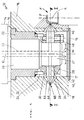
- FIGS. 1 and 2 The embodiment of a hot runner nozzle according to the invention shown in FIGS. 1 and 2 is generally designated 10. It has a connection head 14, which is inserted into a bore 17 of a cavity plate 18 and comes to rest with a shoulder 16 thereon, furthermore a nozzle body 26, which is essentially rotationally symmetrical about an axis 12 and held in a carrier 32 designed here as a bushing is. A central main channel 22 extends through the nozzle body 26 to the lower end of an extension 27.
- a bracket 30 surrounds the neck 27 concentrically. It is fastened to the carrier 32 by means of a poorly heat-conducting spacer ring or basket 34 which has webs 36 arranged at circumferential intervals.
- guide tips 28 are held by a clamping ring 38 which, for. B. can be fixed by means of at least one pressure screw 48 on the holder 30 and thereby clamps the guide tips 28 in the set radial position.
- a recess 40 in the holding elements 30, 38 can cooperate with a collar 42 on the guide tips 28 as a stop.
- the latter extend right up to the sprue end of the inlet cone 44, to which the mold cavity F connects.
- the bore 17 of the cavity plate 18 is closed at the bottom by a bottom 19.
- the material to be processed flows out of the main channel 22 in the direction of arrow M; it is deflected from the bottom 19 to the inlet cones 44, where the guide tips 28 bring about additional heating.
- the readily flowable material therefore passes through an annular gap 68 into the mold cavity F, which contains a suitable mold core K.
- side channels 24 branch off from the main channel 22 in the projection 27 of the nozzle body 26, as indicated by dotted lines in FIG. 1. They extend to the ends of the guide tips 28, which each form a cone 66. If it is withdrawn, material to be processed can exit through the annular gap 68. During the spraying process, it flows through the side channels 24 into the inlet cone 44 and thus into the mold cavity F.
- the arrangement is suitable for both single spraying and multiple spraying, in particular also for articles which have a greater thickness on the wall side in the mold cavity. Since the guide tips 28 can have a selectable inclination to the axis 12, any types of gating are possible.
- a nozzle body 26 which is penetrated by a heatable main channel 22 and which at its lower end 27 has good heat-conducting, displaceable and lockable guide tips with respect to the mold cavity F. 28 has. These can be removed from a heat-conducting holder 30 or arranged to be retractable into its interior, which can be attached to a cylindrical extension 27 of the nozzle body 26 or before it is installed on the mold cavity plate 18.
- the leading tips 28, which terminate with a cone 66, are transverse or inclined to the axis 12 of the nozzle body 26. When the position is withdrawn in the main channel 22 and / or in the side channels 24, they release an injection annular gap 68, which can be partially or completely moved by advancing the cone 66 in question is lockable.
Landscapes
- Engineering & Computer Science (AREA)
- Manufacturing & Machinery (AREA)
- Mechanical Engineering (AREA)
- Moulds For Moulding Plastics Or The Like (AREA)
- Percussion Or Vibration Massage (AREA)
- Injection Moulding Of Plastics Or The Like (AREA)
Abstract
Description
Die vorliegende Erfindung betrifft eine Heißkanaldüse gemäß dem Oberbegriff von Anspruch 1.The present invention relates to a hot runner nozzle according to the preamble of
Heißkanal-Anordnungen mit mehreren Radialkanälen an zungenförmigen Düsenspitzen, um eine Schmelze gleichzeitig über mehrere Einspritzöffnungen in einen Formhohlraum oder in eine Anzahl von Formnestern einzubringen, sind aus DE-A-3 417 220 ersichtlich. Nachteilig sind dabei große Wärmeverluste, die durch das Anliegen der heißen Spitzen an bzw. in der gekühlten Formplatte hervorgerufen werden.DE-A-3 417 220 discloses hot runner arrangements with a plurality of radial ducts on tongue-shaped nozzle tips in order to introduce a melt into a mold cavity or into a number of mold nests simultaneously via a plurality of injection openings. The disadvantage here is large heat losses, which are caused by the hot tips resting on or in the cooled mold plate.
Beispielsweise gemäß DE-A-3 208 339 hat man deshalb schlecht wärmeleitende oder isolierende Dichtungen am Materialübertritt der Düse vorgesehen. Allerdings ist zum seitlichen Anspritzen stets eine Wandung erforderlich, an der am Schluß eines Arbeitstaktes Material erstarrt. Infolgedessen muß beim nächsten Zyklus ein kalter Pfropfen in den zu fertigenden Artikel hineingepreßt werden, was nicht nur eine größere Dicke des Artikels voraussetzt, sondern auch zu Oberflächenfehlern und mangelnder Festigkeit führt.For example, according to DE-A-3 208 339, poorly heat-conducting or insulating seals have therefore been provided at the material transfer of the nozzle. However, a wall is always required for the lateral injection, on which material solidifies at the end of a work cycle. As a result, a cold plug must be pressed into the article to be manufactured in the next cycle, which not only presupposes a larger thickness of the article, but also leads to surface defects and a lack of strength.
Beim Spritzguß sind allgemein enge Temperaturbereiche notwendig, da sonst eine Fadenbildung oder ein Einfrieren des Angusses auftritt. Bei zu niedriger Massetemperatur entsteht ein zu langer kalter Anguß. Dann hat man Probleme etwa beim Aufdrucken eines Verfalldatums, z. B. auf einem Becherboden, oder es entstehen Unebenheiten, so daß sich beispielsweise ein Becher nicht mehr gut stellen läßt. Der Angußbereich am Produkt ist extrem bruchanfällig und ein häufiger Reklamationsgrund.Narrow temperature ranges are generally necessary for injection molding, otherwise thread formation or freezing of the sprue occurs. If the melt temperature is too low, the sprue is too long and cold. Then you have problems such as printing an expiry date, e.g. B. on a cup bottom, or there are bumps, so that for example a cup can no longer be placed well. The sprue area on the product is extremely prone to breakage and is a frequent reason for complaints.
Zur Abhilfe sieht EP-A-0 186 413 ein Heißkanalsystem der eingangs genannten Art vor, wobei der Düsenkörper unten schräg abwärts gerichtete Spitzen aufweist, die von einem im Inneren des Düsenkörpers angeordneten elektrischen Heizstab wärmeleitend unmittelbar erwärmt werden. Schmelzen, die je einen äußeren und einen inneren Kanal parallel durchströmen, sollen dadurch bis zur Vermischung am Austritt, nämlich an seitlichen Einspritzöffnungen des Formnests, fließfähig gehalten werden. In einer hinterschnitten ausgebildeten Formbuchse, die den Düsenkörper mit radialem Abstand umgibt, sind die im wesentlichen zylindrischen Leitspitzen an dessen unterem Ende so befestigt, daß durch ein kleines Loch von unten ein gewünschter radialer Überstand eingestellt werden kann. Das kann jedoch nur von einem Werkzeugmacher und nur beim Einbau durchgeführt werden; nachdem Material eingespritzt wurde, sind Ausbau und Wartung nahezu unmöglich.To remedy this, EP-A-0 186 413 provides a hot runner system of the type mentioned at the outset, the nozzle body having obliquely downwardly directed tips at the bottom which are directly heated in a heat-conducting manner by an electric heating element arranged in the interior of the nozzle body. Melt, which each flow through an outer and an inner channel in parallel, are to be kept fluid until they mix at the outlet, namely at the lateral injection openings of the mold cavity. In an undercut shaped sleeve which surrounds the nozzle body at a radial distance, the substantially cylindrical guide tips are attached to its lower end in such a way that a desired radial projection can be set through a small hole from below. However, this can only be done by a toolmaker and only during installation; after material has been injected, removal and maintenance are almost impossible.
Ziel der Erfindung ist es, die Nachteile des Standes der Technik mit einfachen Mitteln zu überwinden und eine Vorrichtung der genannten Art so weiterzuentwickeln, daß eine Mehrfachanspritzung auf wirtschaftliche Weise durchführbar ist, und zwar auch bei größeren Angußpunkten, mit guter Montagemöglichkeit und unabhängig vom Typ eines später einzusetzenden Heißkanalsystems.The aim of the invention is to overcome the disadvantages of the prior art with simple means and to further develop a device of the type mentioned in such a way that multiple gating can be carried out economically, even at larger gates, with good mounting options and regardless of the type of one hot runner system to be used later.
Hauptmerkmale der Erfindung sind Gegenstand von Anspruch 1. Ausgestaltungen sind in den Ansprüchen 2 bis 8 angegeben.Main features of the invention are the subject of
Bei einer Heißkanaldüse mit einem an einer Formnestplatte befestigbaren Anschlußkopf, an dem ein von einem beheizbaren Hauptkanal für die zu verarbeitende Kunststoffmasse durchsetzter, bedarfsweise mit Verschlußnadeln im Hauptkanal und/oder in zu der Formnestplatte führenden Seitenkanälen versehener Düsenkörper angeordnet ist, der an oder nahe seinem unteren Ende gut wärmeleitende Leitspitzen aufweist, die an einer gut wärmeleitenden Halterung angebracht und in bezug auf das Formnest verschieb- sowie arretierbar sind, sieht die Erfindung gemäß Anspruch 1 vor, daß die Halterung mit einem festsetz- und lösbaren Klemmring für die Leitspitzen versehen ist, der über einen Abstandsring oder -korb mit schlecht wärmeleitenden Stegen an einem Träger befestigt ist. Dadurch ist eine gute Isolierung zum Gehäuse hin gegeben, so daß die Wärmeverluste entsprechend gering sind. Man kann die zunächst am Werkzeug befestigte Halterung später in den Düsenkörper einbauen. Das ist sehr vorteilhaft für die Wartung und Instandhaltung; eventuelle Reparaturen an den aktiven Elementen, z.B. an der Heizeinrichtung der Heißkanaldüse, erfordern daher einen stark verminderten Arbeitsaufwand. Die Leitspitzen sind zur Montage bzw. Demontage entnehmbar oder in das Halterungs-Innere einziehbar. Die gute Wärmeleitung der Halterung sorgt für maximale Wärmeübertragung von der Heißkanaldüse in das Formnest und trägt damit ebenso zur Schnelligkeit wie zur Qualität der energetisch sehr wirtschaftlichen Fertigung bei. Die Wandstärken zum Nest hin können außerdem erheblich dicker, stabiler und gleichmäßiger gestaltet werden, als dies bislang bei seitlicher Anspritzung möglich war.In the case of a hot runner nozzle with a connection head which can be fastened to a mold nest plate, on which a nozzle body which is penetrated by a heatable main duct for the plastic mass to be processed and, if necessary, with sealing needles in the main duct and / or in side ducts leading to the mold nest plate, is arranged on or near its lower one End has good heat-conducting guide tips, which are attached to a good heat-conducting holder and can be moved and locked in relation to the mold cavity, the invention provides according to
Durch die Ausbildung von Anspruch 2, wonach der Düsenkörper in bezug auf eine Achse im wesentlichen rotationssymmetrisch ausgebildet ist und die Halterung eine zylindrischen Ansatz des Düsenkörpers konzentrisch umschließt, erzielt man einen besonders einfachen Aufbau.The embodiment of
Indem der Klemmring gemäß Anspruch 3 mittels wenigstens einer Druckschraube festsetzbar ist, vollzieht sich die Einstellung rasch und präzise, zumal sich am Klemmring und/oder an den Leitspitzen geeignete Rastmittel anordnen lassen. Auch kann nach Anspruch 4 an der Halterung als Zentriermittel eine Ausnehmung vorhanden sein, in die ein zugeordneter Leitspitzen-Bund ragt. Für Montage und Wartung ist es ferner günstig, wenn gemäß Anspruch 5 die in der Halterung sitzenden Leitspitzen durch Einschieben des Düsenkörpers lagefixierbar sind, insbesondere durch Formschluß des Ansatzes mit einem rückseitigen Anschlag der Leitspitzen. Diese können im Einklang mit Anspruch 6 im wesentlichen zylindrisch sein und ein konisches Ende haben, dessen Öffnungswinkel kleiner ist als derjenige eines kalottenförmigen Eintrittskegels, in dem die ausgeschobene Leitspitze bis unmittelbar an das Formnest heranreicht. Man erzielt auf diese Weise eine genaue und zuverlässige Zentrierung.Since the clamping ring can be fixed by means of at least one pressure screw, the setting is carried out quickly and precisely, especially since suitable locking means can be arranged on the clamping ring and / or on the guide tips. According to claim 4, a recess can be provided on the holder as a centering means, into which an associated guide tip collar projects. For assembly and maintenance, it is also advantageous if, according to claim 5, the guide tips sitting in the holder can be fixed in position by inserting the nozzle body, in particular by form-fitting the attachment with a rear stop of the guide tips. In accordance with claim 6, these can be essentially cylindrical and have a conical end, the opening angle of which is smaller than that of a dome-shaped inlet cone, in which the extended guide tip extends right up to the mold cavity. In this way, accurate and reliable centering is achieved.
Für die Montage ist es außerordentlich zweckmäßig, wenn die Formnestplatte gemäß Anspruch 7 zur Aufnahme des Trägers eine Bohrung hat, die unten durch einen Boden abschließbar ist, so daß ein bequemer Zugang geöffnet und geschlossen werden kann. Mithin läßt sich die Halterung in die Formnestplatte von einer Bohrung her, insbesondere wahlweise von der einen wie von der anderen Richtung (oben oder unten) her ein- bzw. ausbauen. Dabei ist es vorteilhaft, wenn laut Anspruch 8 der Anschlußkopf an einer Schulter der Bohrung zur Anlage kommt, wodurch eine exakte Positionierung gewährleistet ist.For assembly, it is extremely useful if the cavity plate according to claim 7 for receiving the carrier has a hole which can be locked at the bottom by a floor, so that easy access can be opened and closed. Thus, the holder in the cavity plate from a hole, in particular optionally from one or from the other direction (up or down) can be installed or removed. It is advantageous if, according to claim 8, the connection head comes to rest on a shoulder of the bore, thereby ensuring exact positioning.
Alle diese Maßnahmen erlauben es, jede beliebige Anspritzart auf einfache Weise durchzuführen. Die Voraussetzungen für ein mehrfaches seitliches Anspritzen lassen sich im Spritzgieß-Werkzeug unabhängig von einem später einzusetzenden Heißkanalsystem schaffen. Außerdem ist ein Austausch der eigentlichen Heißkanaldüse möglich, ohne daß die Halterung mit den Leitspitzen zuvor aus dem Werkzeug demontiert werden müßte. Zu schneller Schußfolge und einwandfreier Qualität trägt es ferner bei, daß die Abdichtung durch den an den kalten Wandungen erstarrten Kunststoff erfolgt.All of these measures make it possible to carry out any type of gating in a simple manner. The requirements for multiple side gating can be created in the injection mold independently of a hot runner system to be used later. In addition, an exchange of the actual hot runner nozzle is possible without the holder with the guide tips having to be removed from the tool beforehand. It also contributes to a quick firing sequence and perfect quality that the sealing takes place through the plastic solidified on the cold walls.
Weitere Merkmale, Einzelheiten und Vorteile der Erfindung ergeben sich aus dem Wortlaut der Ansprüche sowie aus der folgenden Beschreibung eines Ausführungsbeispiels anhand der Zeichnung. Darin zeigen:
- Fig. 1
- eine Teil-Axialschnittstelle einer in eine Formnestplatte eingebauten Heißkanaldüse, und
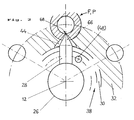
- Fig. 2
- eine Druntersicht, teilweise im Schnitt entsprechend der Linie II-II von Fig. 1, eines demgegenüber um 90° versetzten Düsenkörpers.
- Fig. 1
- a partial axial interface of a hot runner nozzle installed in a cavity plate, and
- Fig. 2
- a bottom view, partly in section along the line II-II of Fig. 1, a nozzle body offset by 90 °.
Die in Fig. 1 und 2 dargestellte Ausführungsform einer erfindungsgemäßen Heißkanaldüse ist allgemein mit 10 bezeichnet. Sie hat einen Anschlußkopf 14, der in eine Bohrung 17 einer Formnestplatte 18 eingesetzt ist und an dieser mit einer Schulter 16 zur Anlage kommt, ferner einen Düsenkörper 26, der zu einer Achse 12 im wesentlichen rotationssymmetrisch und in einem hier als Buchse ausgebildeten Träger 32 gehalten ist. Ein zentral verlaufender Hauptkanal 22 durchsetzt den Düsenkörper 26 bis zum unteren Ende eines Ansatzes 27 hin.The embodiment of a hot runner nozzle according to the invention shown in FIGS. 1 and 2 is generally designated 10. It has a
Eine Halterung 30 umgibt den Ansatz 27 konzentrisch. Sie ist an dem Träger 32 mittels eines schlecht wärmeleitenden Abstandsringes oder -korbes 34 befestigt, der in Umfangsabständen angeordnete Stege 36 aufweist.A
In der Halterung 30 sind Leitspitzen 28 durch einen Klemmring 38 gehalten, der z. B. mittels wenigstens einer Druckschraube 48 an der Halterung 30 festsetzbar ist und dabei die Leitspitzen 28 in der eingestellten Radialposition festklemmt. Um die Zentrierung zu unterstützen, kann eine Ausnehmung 40 in den Halteelementen 30, 38 mit einem Bund 42 an den Leitspitzen 28 als Anschlag zusammenwirken.In the
Die konischen Enden 66 der Leitspitzen 28, deren Hauptteil zylindrische Gestalt hat, münden in einem Formnesteinsatz 46 in Aussparungen, die als kalottenförmige Eintrittskegel 44 mit einem Öffnungswinkel ausgebildet sind, der jenen der Leitspitzen 28 deutlich überschreitet. Letztere reichen bis unmittelbar an das Angußende der Eintrittskegel 44 heran, an die das Formnest F anschließt. Die Bohrung 17 der Formnestplatte 18 ist unten durch einen Boden 19 abgeschlossen. Das zu verarbeitende Material strömt in Pfeilrichtung M aus dem Hauptkanal 22 aus; es wird von dem Boden 19 zu den Eintrittskegeln 44 umgelenkt, wo die Leitspitzen 28 eine zusätzliche Erwärmung bewirken. Daher gelangt das gut fließfähige Material durch einen Ringspalt 68 in das Formnest F, das einen geeigneten Formkern K enthält.The
Es ist auch möglich und erfindungsgemäß vorgesehen, daß im Ansatz 27 des Düsenkörpers 26 von dem Hauptkanal 22 Seitenkanäle 24 abzweigen, wie in Fig. 1 gepunktet angedeutet. Sie reichen bis an die Enden der Leitspitzen 28, die jeweils einen Konus 66 bilden. Ist er zurückgezogen, so kann zu verarbeitendes Material durch den Ringspalt 68 austreten. Es fließt beim Spritzvorgang durch die Seitenkanäle 24 in die Eintrittskegel 44 und damit in das Formnest F. Die Anordnung eignet sich sowohl zum Einfachspritzen als auch zur Mehrfachanspritzung, und zwar insbesondere auch für Artikel, die wandseitig im Formnest größere Dicke aufweisen. Da die Leitspitzen 28 eine wählbare Neigung zur Achse 12 haben können, sind beliebige Anspritzarten möglich.It is also possible and provided according to the invention that
Die Erfindung ist nicht auf die dargestellten Ausführungsformen beschränkt. Man erkennt aber, daß bei einer bevorzugten Ausführungsform an einem Anschlußkopf 14 einer Heißkanaldüse 10 zu einer Formnestplatte 18 ein von einem beheizbaren Hauptkanal 22 durchsetzter Düsenkörper 26 sitzt, der an seinem unteren Ende 27 gut wärmeleitende, in bezug auf das Formnest F verschiebbare und arretierbare Leitspitzen 28 aufweist. Diese sind an einer wärmeleitenden Halterung 30 entnehmbar oder in ihr Inneres einziehbar angeordnet, die an einem zylindrischen Ansatz 27 des Düsenkörper 26 oder vor dessen Einbau an der Formnestplatte 18 anbringbar ist. Die mit einem Konus 66 auslaufenden Leitspitzen 28 stehen quer oder geneigt zur Achse 12 des Düsenkörpers 26. Sie geben bei zurückgezogener Stellung im Hauptkanal 22 und/oder in Seitenkanälen 24 einen Einspritz-Ringspalt 68 frei, der durch Vorschieben des betreffenden Konus 66 teilweise oder ganz verschließbar ist.The invention is not restricted to the illustrated embodiments. It can be seen, however, that in a preferred embodiment, on a connecting
Claims (8)
- Hot runner nozzle (10) for injection moulding apparatus including a connecting block (14) adapted to be attached to a cavity plate (18) and provided with a nozzle body (26) through which a heatable main runner (22) for the plastic mass to be processed extends, if required with plug needles in the main runner and/or in side runners (24) leading to the cavity plate (18), the nozzle body (26) comprising at or near its lower end (27) conducting points (28) of good heat conduction which are fixed to a mount (30) of good heat conduction and are slideable and fixable relative to the mould cavity (F), wherein the mount (30) comprises an attachable and detachable clamping ring (38) for the conducting points (28), said clamping ring (38) being fixed to a support (32) by means of a distance ring or basket (34) having fingers (36) of poor heat conduction.
- Hot runner nozzle according to claim 1, wherein the nozzle body (26) is substantially rotation-symmetrical relative to an axis (12) and wherein the mount (30) concentrically encloses a cylindrical stud (27) of the nozzle body (26).
- Hot runner nozzle according to claim 1 or claim 2, wherein the clamping ring (38) is fixable by means of at least one pressing screw (48).
- Hot runner nozzle according to any one of claims 1 to 3, wherein as a centering means, the mount (30) includes a recess (40) into which an associated shoulder (42) of the conducting points (28) extends.
- Hot runner nozzle according to any one of claims 1 to 4, wherein the conducting points (28) seated in the mount (30, 38) are adapted to be fixed in their position by slidingly inserting the nozzle body (26), particularly through form-fit of the stud (27) with a rear stop (42) of the conducting points (28).
- Hot runner nozzle according to any one of claims 1 to 5, wherein each conducting point (28) comprises a main portion of cylindrical shape and a conical end portion having an included angle which is smaller than that of a calotte-shaped entrance cone (48) in which the respective extended conducting point (28) reaches directly to the mould cavity (F).
- Hot runner nozzle according to any one of claims 1 to 6, wherein for receiving the support (32), the cavity plate (18) comprises a bore (17) adapted to be closed below by a bottom plate (19).
- Hot runner nozzle according to claim 7, wherein a shoulder (16) of the bore (17) engages the connecting block (14).
Priority Applications (5)
| Application Number | Priority Date | Filing Date | Title |
|---|---|---|---|
| EP90105053A EP0447573B1 (en) | 1990-03-17 | 1990-03-17 | Hot runner nozzle |
| DE59009475T DE59009475D1 (en) | 1990-03-17 | 1990-03-17 | Hot runner nozzle. |
| DE9003574U DE9003574U1 (en) | 1990-03-17 | 1990-03-17 | Hot runner nozzle |
| ES90105053T ES2077596T3 (en) | 1990-03-17 | 1990-03-17 | HOT CHANNEL NOZZLE. |
| AT90105053T ATE125746T1 (en) | 1990-03-17 | 1990-03-17 | HOT CHANNEL NOZZLE. |
Applications Claiming Priority (1)
| Application Number | Priority Date | Filing Date | Title |
|---|---|---|---|
| EP90105053A EP0447573B1 (en) | 1990-03-17 | 1990-03-17 | Hot runner nozzle |
Publications (2)
| Publication Number | Publication Date |
|---|---|
| EP0447573A1 EP0447573A1 (en) | 1991-09-25 |
| EP0447573B1 true EP0447573B1 (en) | 1995-08-02 |
Family
ID=8203763
Family Applications (1)
| Application Number | Title | Priority Date | Filing Date |
|---|---|---|---|
| EP90105053A Expired - Lifetime EP0447573B1 (en) | 1990-03-17 | 1990-03-17 | Hot runner nozzle |
Country Status (4)
| Country | Link |
|---|---|
| EP (1) | EP0447573B1 (en) |
| AT (1) | ATE125746T1 (en) |
| DE (1) | DE59009475D1 (en) |
| ES (1) | ES2077596T3 (en) |
Cited By (2)
| Publication number | Priority date | Publication date | Assignee | Title |
|---|---|---|---|---|
| US7658605B2 (en) | 2006-12-29 | 2010-02-09 | Mold-Masters (2007) Limited | Edge gated injection molding apparatus |
| US7658606B2 (en) | 2006-12-22 | 2010-02-09 | Mold-Masters (2007) Limited | Edge gated injection molding apparatus |
Families Citing this family (13)
| Publication number | Priority date | Publication date | Assignee | Title |
|---|---|---|---|---|
| DE10231093C1 (en) * | 2002-07-10 | 2003-10-30 | Otto Maenner Heiskanalsysteme | Injection jet, for plastics injection molding, has at least two opposing outflow openings at different sides, each with a closure needle to prevent the formation of a cold plug at the opening mouth |
| DE10345578A1 (en) | 2003-09-29 | 2005-05-12 | Hans Schreck | Device for injecting in particular plastic moldings |
| US7410353B2 (en) | 2004-10-20 | 2008-08-12 | Mold-Masters (2007) Limited | Edge gated injection molding apparatus |
| US7396226B2 (en) | 2006-03-10 | 2008-07-08 | Mold-Masters (2007) Limited | Nozzle sealing assembly |
| CA2591729A1 (en) | 2006-06-16 | 2007-12-16 | Mold-Masters Limited | Individual cavity shut-off valve for an injection molding apparatus |
| US7803306B2 (en) | 2006-06-16 | 2010-09-28 | Mold-Masters (2007) Limited | Individual cavity shut-off valve for an injection molding apparatus |
| DE102008028577B4 (en) | 2007-06-20 | 2016-11-10 | Mold-Masters (2007) Limited | Eckenangussspritzgießvorrichtung |
| DE202008005073U1 (en) | 2008-04-11 | 2008-07-03 | EWIKON Heißkanalsysteme GmbH & Co. KG | Hot runner nozzle for Seitenanspritzung |
| US7794228B2 (en) | 2008-04-29 | 2010-09-14 | Mold-Masters (2007) Limited | Injection molding apparatus having an edge-gated runnerless nozzle |
| EP2243613A1 (en) * | 2009-04-21 | 2010-10-27 | Hans Schreck | Nozzle device and method for injecting plastic moulded parts |
| DE202009004786U1 (en) | 2009-05-06 | 2010-09-23 | EWIKON Heißkanalsysteme GmbH & Co. KG | Hot runner nozzle for Seitenanspritzung |
| US9174372B2 (en) | 2013-03-15 | 2015-11-03 | Sabic Global Technologies B.V. | Shut off nozzle system and methods for making and using the same |
| CN117620605B (en) * | 2023-11-28 | 2026-02-24 | 大连工业大学 | Processing method of nozzle for coke oven gas pre-desulfurization |
Family Cites Families (3)
| Publication number | Priority date | Publication date | Assignee | Title |
|---|---|---|---|---|
| US4304544A (en) * | 1974-10-21 | 1981-12-08 | Fast Heat Element Mfg. Co., Inc. | Electrically heated nozzles and nozzle systems |
| GB8432451D0 (en) * | 1984-12-21 | 1985-02-06 | Tanner Ag | Injection moulding of plastics |
| DE3545002A1 (en) * | 1985-12-19 | 1987-07-02 | Reiss Int Gmbh | Process for injection moulding plastic parts from thermosets |
-
1990
- 1990-03-17 DE DE59009475T patent/DE59009475D1/en not_active Expired - Fee Related
- 1990-03-17 AT AT90105053T patent/ATE125746T1/en not_active IP Right Cessation
- 1990-03-17 ES ES90105053T patent/ES2077596T3/en not_active Expired - Lifetime
- 1990-03-17 EP EP90105053A patent/EP0447573B1/en not_active Expired - Lifetime
Cited By (2)
| Publication number | Priority date | Publication date | Assignee | Title |
|---|---|---|---|---|
| US7658606B2 (en) | 2006-12-22 | 2010-02-09 | Mold-Masters (2007) Limited | Edge gated injection molding apparatus |
| US7658605B2 (en) | 2006-12-29 | 2010-02-09 | Mold-Masters (2007) Limited | Edge gated injection molding apparatus |
Also Published As
| Publication number | Publication date |
|---|---|
| DE59009475D1 (en) | 1995-09-07 |
| ATE125746T1 (en) | 1995-08-15 |
| EP0447573A1 (en) | 1991-09-25 |
| ES2077596T3 (en) | 1995-12-01 |
Similar Documents
| Publication | Publication Date | Title |
|---|---|---|
| EP0447573B1 (en) | Hot runner nozzle | |
| DE2709609C2 (en) | Valve-controlled inlet part for injection molding tools | |
| DE69008894T2 (en) | Injection molding device with gas flow through the valve opening. | |
| DE69914509T2 (en) | Process for producing a three-part injection molding nozzle and an injection mold cavity insert and for cooling a mold cavity | |
| CH693171A5 (en) | Method and device for cooling plastic molded articles after molding. | |
| DE69603538T2 (en) | Injection molding device with side gate with radially mounted gate inserts | |
| EP1654105A1 (en) | Injection molding nozzle | |
| DE10354456A1 (en) | Hot runner nozzle for injection molding apparatus includes an alignment piece positioned between a tip removably attached to a nozzle body and tip surrounding piece removably connected to the nozzle body | |
| DE3942957C2 (en) | Device for introducing a metered gas volume into a mold cavity of an injection mold filled with a plastic melt | |
| DE102004017276A1 (en) | Front-mounted nozzle with a side sprue | |
| DE3912209A1 (en) | INJECTION MOLDING DEVICE WITH NOZZLE LOCKING SYSTEM | |
| EP0528316B1 (en) | Injection moulding device with hot runner nozzle | |
| EP1603729B1 (en) | Needle valve nozzle | |
| DE9003574U1 (en) | Hot runner nozzle | |
| DE19618957A1 (en) | Injection molded side gate with hot tip and peripheral rib | |
| EP3398749A1 (en) | Insert for use in an injection molding nozzle and injection molding nozzle with such an insert | |
| DE69217794T2 (en) | Injection molding device with torpedo with angled tip | |
| WO1998019847A1 (en) | Injection moulding nozzle | |
| EP3524402B1 (en) | Needle shut-off nozzle with a separate needle channel and melt channel | |
| EP2209601A2 (en) | Injection moulding nozzle | |
| EP0284920B1 (en) | Hot channel for plastic injection moulding machines | |
| DE112006000474B4 (en) | injection molding | |
| DE4132986C2 (en) | Nozzle arrangement for injection molding of large-area plastic parts with enclosed cavities | |
| EP0321678B1 (en) | Injection nozzle and injection-moulding apparatus | |
| DE4414005A1 (en) | Process for sheathing electronic components |
Legal Events
| Date | Code | Title | Description |
|---|---|---|---|
| PUAI | Public reference made under article 153(3) epc to a published international application that has entered the european phase |
Free format text: ORIGINAL CODE: 0009012 |
|
| 17P | Request for examination filed |
Effective date: 19901220 |
|
| AK | Designated contracting states |
Kind code of ref document: A1 Designated state(s): AT BE CH DE DK ES FR GB GR IT LI LU NL SE |
|
| RBV | Designated contracting states (corrected) |
Designated state(s): AT BE DE ES FR GB NL |
|
| RAP1 | Party data changed (applicant data changed or rights of an application transferred) |
Owner name: DIPL.-ING. HERBERT GUENTHER GESELLSCHAFT MBH |
|
| 17Q | First examination report despatched |
Effective date: 19930226 |
|
| GRAA | (expected) grant |
Free format text: ORIGINAL CODE: 0009210 |
|
| AK | Designated contracting states |
Kind code of ref document: B1 Designated state(s): AT BE DE ES FR GB NL |
|
| REF | Corresponds to: |
Ref document number: 125746 Country of ref document: AT Date of ref document: 19950815 Kind code of ref document: T |
|
| REF | Corresponds to: |
Ref document number: 59009475 Country of ref document: DE Date of ref document: 19950907 |
|
| ET | Fr: translation filed | ||
| GBT | Gb: translation of ep patent filed (gb section 77(6)(a)/1977) |
Effective date: 19950908 |
|
| REG | Reference to a national code |
Ref country code: ES Ref legal event code: FG2A Ref document number: 2077596 Country of ref document: ES Kind code of ref document: T3 |
|
| PG25 | Lapsed in a contracting state [announced via postgrant information from national office to epo] |
Ref country code: GB Effective date: 19960317 Ref country code: AT Effective date: 19960317 |
|
| PG25 | Lapsed in a contracting state [announced via postgrant information from national office to epo] |
Ref country code: ES Free format text: LAPSE BECAUSE OF NON-PAYMENT OF DUE FEES Effective date: 19960318 |
|
| PG25 | Lapsed in a contracting state [announced via postgrant information from national office to epo] |
Ref country code: BE Effective date: 19960331 |
|
| PLBE | No opposition filed within time limit |
Free format text: ORIGINAL CODE: 0009261 |
|
| STAA | Information on the status of an ep patent application or granted ep patent |
Free format text: STATUS: NO OPPOSITION FILED WITHIN TIME LIMIT |
|
| 26N | No opposition filed | ||
| BERE | Be: lapsed |
Owner name: HERBERT GUNTHER G.M.B.H. Effective date: 19960331 |
|
| PG25 | Lapsed in a contracting state [announced via postgrant information from national office to epo] |
Ref country code: NL Effective date: 19961001 |
|
| GBPC | Gb: european patent ceased through non-payment of renewal fee |
Effective date: 19960317 |
|
| PG25 | Lapsed in a contracting state [announced via postgrant information from national office to epo] |
Ref country code: FR Effective date: 19961129 |
|
| NLV4 | Nl: lapsed or anulled due to non-payment of the annual fee |
Effective date: 19961001 |
|
| REG | Reference to a national code |
Ref country code: FR Ref legal event code: ST |
|
| PG25 | Lapsed in a contracting state [announced via postgrant information from national office to epo] |
Ref country code: DE Effective date: 19970902 |
|
| REG | Reference to a national code |
Ref country code: ES Ref legal event code: FD2A Effective date: 19990201 |