EP0447596A1 - Capteur de température - Google Patents
Capteur de température Download PDFInfo
- Publication number
- EP0447596A1 EP0447596A1 EP90105565A EP90105565A EP0447596A1 EP 0447596 A1 EP0447596 A1 EP 0447596A1 EP 90105565 A EP90105565 A EP 90105565A EP 90105565 A EP90105565 A EP 90105565A EP 0447596 A1 EP0447596 A1 EP 0447596A1
- Authority
- EP
- European Patent Office
- Prior art keywords
- measuring resistor
- cover layer
- temperature sensor
- glass
- protective layer
- Prior art date
- Legal status (The legal status is an assumption and is not a legal conclusion. Google has not performed a legal analysis and makes no representation as to the accuracy of the status listed.)
- Granted
Links
- BASFCYQUMIYNBI-UHFFFAOYSA-N platinum Chemical compound [Pt] BASFCYQUMIYNBI-UHFFFAOYSA-N 0.000 claims abstract description 24
- 239000010410 layer Substances 0.000 claims abstract description 21
- 239000011241 protective layer Substances 0.000 claims abstract description 16
- 239000011521 glass Substances 0.000 claims abstract description 12
- 229910052697 platinum Inorganic materials 0.000 claims abstract description 12
- 239000000758 substrate Substances 0.000 claims abstract description 7
- PXHVJJICTQNCMI-UHFFFAOYSA-N Nickel Chemical compound [Ni] PXHVJJICTQNCMI-UHFFFAOYSA-N 0.000 claims abstract description 6
- ZOKXTWBITQBERF-UHFFFAOYSA-N Molybdenum Chemical compound [Mo] ZOKXTWBITQBERF-UHFFFAOYSA-N 0.000 claims abstract description 3
- 229910052750 molybdenum Inorganic materials 0.000 claims abstract description 3
- 239000011733 molybdenum Substances 0.000 claims abstract description 3
- 229910052759 nickel Inorganic materials 0.000 claims abstract description 3
- 230000001419 dependent effect Effects 0.000 claims abstract 2
- 229910052751 metal Inorganic materials 0.000 claims description 3
- 239000002184 metal Substances 0.000 claims description 3
- 238000004544 sputter deposition Methods 0.000 claims description 3
- VYZAMTAEIAYCRO-UHFFFAOYSA-N Chromium Chemical compound [Cr] VYZAMTAEIAYCRO-UHFFFAOYSA-N 0.000 claims description 2
- 239000000919 ceramic Substances 0.000 claims description 2
- 230000007613 environmental effect Effects 0.000 claims 1
- 238000007740 vapor deposition Methods 0.000 claims 1
- 230000005855 radiation Effects 0.000 abstract description 6
- 230000006378 damage Effects 0.000 abstract description 5
- 239000010409 thin film Substances 0.000 abstract description 4
- 239000000463 material Substances 0.000 abstract description 3
- 238000005259 measurement Methods 0.000 description 5
- 239000002241 glass-ceramic Substances 0.000 description 4
- 230000000694 effects Effects 0.000 description 2
- 238000005516 engineering process Methods 0.000 description 2
- 239000010408 film Substances 0.000 description 2
- 238000002844 melting Methods 0.000 description 2
- 230000008018 melting Effects 0.000 description 2
- 150000002739 metals Chemical class 0.000 description 2
- 229910000510 noble metal Inorganic materials 0.000 description 2
- OKTJSMMVPCPJKN-UHFFFAOYSA-N Carbon Chemical compound [C] OKTJSMMVPCPJKN-UHFFFAOYSA-N 0.000 description 1
- 229910052804 chromium Inorganic materials 0.000 description 1
- 239000011651 chromium Substances 0.000 description 1
- 239000011248 coating agent Substances 0.000 description 1
- 238000000576 coating method Methods 0.000 description 1
- 238000010438 heat treatment Methods 0.000 description 1
- 238000000034 method Methods 0.000 description 1
- 238000007650 screen-printing Methods 0.000 description 1
- 238000010408 sweeping Methods 0.000 description 1
- XLYOFNOQVPJJNP-UHFFFAOYSA-N water Substances O XLYOFNOQVPJJNP-UHFFFAOYSA-N 0.000 description 1
Images
Classifications
-
- G—PHYSICS
- G01—MEASURING; TESTING
- G01K—MEASURING TEMPERATURE; MEASURING QUANTITY OF HEAT; THERMALLY-SENSITIVE ELEMENTS NOT OTHERWISE PROVIDED FOR
- G01K1/00—Details of thermometers not specially adapted for particular types of thermometer
- G01K1/08—Protective devices, e.g. casings
- G01K1/10—Protective devices, e.g. casings for preventing chemical attack
Definitions
- the invention relates to a temperature sensor according to the preamble of claim 1.
- Such temperature sensors contain e.g. a platinum thin or thick film resistor as an accurate and stable temperature measuring element. They can be used, among other things, in devices for measuring the mass of a flowing gaseous medium, e.g. as an air mass meter for the intake tract of a motor vehicle engine.
- the platinum of the thin-film resistor is so chemically stable and so adherently applied to a substrate that it could also be used as a measuring element with an unprotected surface.
- it is very sensitive to mechanical damage when annealed. Such damage can easily change the resistance value of the thin film resistor and thus lead to measurement errors. It is therefore known to cover the thin-film resistor with a glass-ceramic insulating layer (special print from conference reports "Sensor 82", Degussa measurement technology No. 8202).
- the temperature sensor is used in a humid environment, the coincidence of electrical voltage in the resistance layer and moisture from the environment in the glass cover layer can lead to pitting and cracks, which can result in the sensor being destroyed.
- the invention has for its object to provide a temperature sensor that is insensitive to electrochemical damage to the glass-like or glass-ceramic cover layer.
- a temperature sensor with the features of claim 1.
- the basic idea of the invention is to additionally cover the mentioned cover layer with a protective layer made of an inert, noble metal, e.g. with a protective layer made of platinum.
- a particular advantage is that the heat radiation of the measuring element designed as a low-resistance hot film resistor is greatly reduced, which leads to a considerable reduction in the measurement error, particularly in the idling range, in the case of intake air mass meters.
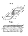
- a temperature sensor 1 contains a substrate 2 made of glass or glass ceramic, on which a layered measuring resistor 3, for example made of platinum, is applied (FIG. 1).
- the substrate 2 is about 180 microns thick, the measuring resistor 3 about 1 micron.
- platinum is applied by sputtering, ie by cathode sputtering, and then cut with a laser cutter along cutting lines 4, so that a meandering course of the layered measuring resistor 3 results.
- a cover layer 6 made of glass or glass ceramic is applied to the measuring resistor 3, expediently using the screen printing method.
- the cover layer 6 is about 10 microns thick and it does not completely cover the measuring resistor 3, but rather leaves a connection area 7 at both ends to which the measuring resistor 3 is soldered.
- a protective layer 8 made of platinum or of another noble metal is additionally sputtered or vapor-deposited onto the cover layer 6.
- the protective layer 8 is approximately 100 nm thick and must not have any contact with the connection regions 7.
- a distance 9 of about 0.5 to 1 mm must therefore remain free on both sides.
- the measuring resistor 3 has an active sensor surface with a length of 10, the protective layer 8 must extend on both sides at least 0.5 mm beyond the length 10, the active sensor surface must be "covered”.
- the substrate 2 on a side 11 of at least 30 ⁇ m must remain free of the measuring resistor 3, i.e. this must not reach the edges.
- the substrate 2 is covered here directly by the cover layer 6 (cf. also FIG. 2).
- the metallic protective layer 8 has the effect that the covering layer 6 lying above the active surface (length 10) no longer comes into contact with water or aggressive air, and thus the temperature sensor 1 can no longer be destroyed under its action.
- the protective layer 8 also acts as a reflective coating of the layered resistor 3 and reduces the heat radiation emitted by it quite considerably.
- An air mass measuring device essentially contains two temperature sensors 1 designed as glass-based chips, one of which has a resistance value of 1000 ohms and serves as a temperature sensor and the other has 9 ohms and serves as a heating element. In principle, it is also a temperature sensor that is operated with excessive current.
- the heat given off is a measure of the air mass flow sweeping over the temperature sensor. Since this is low when the engine is idling, the amount of heat dissipated to it is also small, the proportion of the amount of heat given off by radiation is much larger here and has an effect on the measurement inaccuracy. Because the protective layer 8 reduces the heat radiation, it significantly improves the measuring accuracy of the temperature sensor, particularly in the idle range. In one embodiment, the measurement error in idle was reduced to half.
- the measuring resistor 3 can also be made from molybdenum, nickel or similar metals.
- the cover layer 6 can consist of glass, but also of ceramic, plastic or other suitable materials.
- the protective layer 8 can also be produced from chromium or similar inert metals in addition to platinum.
Landscapes
- Physics & Mathematics (AREA)
- General Physics & Mathematics (AREA)
- Thermistors And Varistors (AREA)
- Measuring Volume Flow (AREA)
Priority Applications (2)
| Application Number | Priority Date | Filing Date | Title |
|---|---|---|---|
| EP19900105565 EP0447596B1 (fr) | 1990-03-23 | 1990-03-23 | Capteur de température |
| DE59006062T DE59006062D1 (de) | 1990-03-23 | 1990-03-23 | Temperaturfühler. |
Applications Claiming Priority (1)
| Application Number | Priority Date | Filing Date | Title |
|---|---|---|---|
| EP19900105565 EP0447596B1 (fr) | 1990-03-23 | 1990-03-23 | Capteur de température |
Publications (2)
| Publication Number | Publication Date |
|---|---|
| EP0447596A1 true EP0447596A1 (fr) | 1991-09-25 |
| EP0447596B1 EP0447596B1 (fr) | 1994-06-08 |
Family
ID=8203801
Family Applications (1)
| Application Number | Title | Priority Date | Filing Date |
|---|---|---|---|
| EP19900105565 Expired - Lifetime EP0447596B1 (fr) | 1990-03-23 | 1990-03-23 | Capteur de température |
Country Status (2)
| Country | Link |
|---|---|
| EP (1) | EP0447596B1 (fr) |
| DE (1) | DE59006062D1 (fr) |
Cited By (1)
| Publication number | Priority date | Publication date | Assignee | Title |
|---|---|---|---|---|
| WO2012167009A1 (fr) * | 2011-06-03 | 2012-12-06 | Cree, Inc. | Résistance à couche mince et son procédé de fabrication |
Families Citing this family (3)
| Publication number | Priority date | Publication date | Assignee | Title |
|---|---|---|---|---|
| DE19530413C1 (de) * | 1995-08-18 | 1997-04-03 | Heraeus Sensor Gmbh | Verfahren zur Befestigung und Kontaktierung von Widerstandselementen für Heißfilmanemometer sowie Sensoranordnung |
| DE102017104162A1 (de) | 2017-02-28 | 2018-08-30 | Innovative Sensor Technology Ist Ag | Sensorelement und thermischer Strömungssensor zur Bestimmung einer physikalischen Größe eines Messmediums |
| CN112013982A (zh) * | 2020-09-08 | 2020-12-01 | 济南南知信息科技有限公司 | 一种嵌入式铂电偶传感器 |
Citations (4)
| Publication number | Priority date | Publication date | Assignee | Title |
|---|---|---|---|---|
| US3891467A (en) * | 1973-05-29 | 1975-06-24 | Robertshaw Controls Co | Thermocouple with a diffused chromium casing |
| EP0063645A2 (fr) * | 1981-03-26 | 1982-11-03 | Robert Bosch Gmbh | Capteur de température rapide pour moteur à combustion |
| DE3117827A1 (de) * | 1981-05-06 | 1982-11-25 | Draloric Electronic GmbH, 6000 Frankfurt | Verfahren zur herstellung von messwiderstaenden fuer widerstandsthermometer und vorrichtung zur durchfuehrung des verfahrens |
| WO1987005146A1 (fr) * | 1986-02-13 | 1987-08-27 | Rosemount Inc. | Thermometre a resistance en platine en fine pellicule avec barriere de diffusion a haute temperature |
-
1990
- 1990-03-23 DE DE59006062T patent/DE59006062D1/de not_active Expired - Fee Related
- 1990-03-23 EP EP19900105565 patent/EP0447596B1/fr not_active Expired - Lifetime
Patent Citations (4)
| Publication number | Priority date | Publication date | Assignee | Title |
|---|---|---|---|---|
| US3891467A (en) * | 1973-05-29 | 1975-06-24 | Robertshaw Controls Co | Thermocouple with a diffused chromium casing |
| EP0063645A2 (fr) * | 1981-03-26 | 1982-11-03 | Robert Bosch Gmbh | Capteur de température rapide pour moteur à combustion |
| DE3117827A1 (de) * | 1981-05-06 | 1982-11-25 | Draloric Electronic GmbH, 6000 Frankfurt | Verfahren zur herstellung von messwiderstaenden fuer widerstandsthermometer und vorrichtung zur durchfuehrung des verfahrens |
| WO1987005146A1 (fr) * | 1986-02-13 | 1987-08-27 | Rosemount Inc. | Thermometre a resistance en platine en fine pellicule avec barriere de diffusion a haute temperature |
Non-Patent Citations (1)
| Title |
|---|
| NASA TECH BRIEFS. no. 4H, April 1985, WASHINGTON US RICHTER: "OXIDATION PROTECTION FOR THERMOCOUPLES" * |
Cited By (2)
| Publication number | Priority date | Publication date | Assignee | Title |
|---|---|---|---|---|
| WO2012167009A1 (fr) * | 2011-06-03 | 2012-12-06 | Cree, Inc. | Résistance à couche mince et son procédé de fabrication |
| US8570140B2 (en) | 2011-06-03 | 2013-10-29 | Cree, Inc. | Thin film resistor |
Also Published As
| Publication number | Publication date |
|---|---|
| DE59006062D1 (de) | 1994-07-14 |
| EP0447596B1 (fr) | 1994-06-08 |
Similar Documents
| Publication | Publication Date | Title |
|---|---|---|
| DE2954739C2 (de) | Anordnung zur Durchsatzmessung der Ansaugluft einer Brennkraftmaschine | |
| EP0973020B1 (fr) | Capteur de température électrique comprenant une multi-couche | |
| DE4035371C2 (de) | Kapazitiver Feuchtesensor | |
| EP3327415B1 (fr) | Thermomètre à résistance | |
| DE19801484A1 (de) | Meßelement und damit ausgerüsteter Luftmassenmesser | |
| EP0021291A1 (fr) | Débitmètre | |
| EP0571412A1 (fr) | Capteur en metal du groupe du platine pour hautes temperatures | |
| CH663844A5 (de) | Thermischer massendurchflussmesser, insbesondere fuer gase. | |
| WO1998026260A1 (fr) | Resistance electrique avec au moins deux champs de contact sur un substrat en ceramique et son procede de fabrication | |
| AT403851B (de) | Widerstandsthermometer mit einem messwiderstand | |
| EP2435797A2 (fr) | Élément capteur | |
| EP0063645B1 (fr) | Capteur de température rapide pour moteur à combustion | |
| EP0447596B1 (fr) | Capteur de température | |
| DE19800628C2 (de) | Luftdurchsatz-Meßelement und Luftdurchsatz-Meßvorrichtung | |
| DE19941420A1 (de) | Elektrischer Widerstand mit wenigstens zwei Anschlußkontaktfeldern auf einem Substrat mit wenigstens einer Ausnehmung sowie Verfahren zu dessen Herstellung | |
| DE1648241C3 (de) | Maximumthermometer für Oberflächentemperaturen | |
| DE102017104162A1 (de) | Sensorelement und thermischer Strömungssensor zur Bestimmung einer physikalischen Größe eines Messmediums | |
| DE2558752B2 (de) | Verfahren zur Herstellung eines Schichtwiderstandes als MeBwiderstand für Widerstandsthermometer | |
| EP2454571B1 (fr) | Élément de détection pour déterminer au moins une grandeur physique | |
| EP1248968B1 (fr) | Dispositif de mesure et de regulation de temperature | |
| DE19932411A1 (de) | Verfahren zur Herstellung eines temperaturabhängigen Widerstandes sowie elektrischer Temperatur-Sensor | |
| EP0446667A2 (fr) | Capteur de températures | |
| DE4223432A1 (de) | Gassensor mit einem temperaturfuehler | |
| DE9202705U1 (de) | Temperaturmeßfühler | |
| DE102018130547A1 (de) | Sensorelement, Verfahren zu dessen Herstellung und thermischer Strömungssensor |
Legal Events
| Date | Code | Title | Description |
|---|---|---|---|
| PUAI | Public reference made under article 153(3) epc to a published international application that has entered the european phase |
Free format text: ORIGINAL CODE: 0009012 |
|
| 17P | Request for examination filed |
Effective date: 19901205 |
|
| AK | Designated contracting states |
Kind code of ref document: A1 Designated state(s): AT BE CH DE DK ES FR GB GR IT LI LU NL SE |
|
| RBV | Designated contracting states (corrected) |
Designated state(s): DE FR GB IT |
|
| 17Q | First examination report despatched |
Effective date: 19930716 |
|
| GRAA | (expected) grant |
Free format text: ORIGINAL CODE: 0009210 |
|
| AK | Designated contracting states |
Kind code of ref document: B1 Designated state(s): DE FR GB IT |
|
| REF | Corresponds to: |
Ref document number: 59006062 Country of ref document: DE Date of ref document: 19940714 |
|
| ITF | It: translation for a ep patent filed | ||
| GBT | Gb: translation of ep patent filed (gb section 77(6)(a)/1977) |
Effective date: 19940824 |
|
| ET | Fr: translation filed | ||
| PLBE | No opposition filed within time limit |
Free format text: ORIGINAL CODE: 0009261 |
|
| STAA | Information on the status of an ep patent application or granted ep patent |
Free format text: STATUS: NO OPPOSITION FILED WITHIN TIME LIMIT |
|
| 26N | No opposition filed | ||
| PGFP | Annual fee paid to national office [announced via postgrant information from national office to epo] |
Ref country code: GB Payment date: 19990305 Year of fee payment: 10 |
|
| PG25 | Lapsed in a contracting state [announced via postgrant information from national office to epo] |
Ref country code: GB Free format text: LAPSE BECAUSE OF NON-PAYMENT OF DUE FEES Effective date: 20000323 |
|
| PGFP | Annual fee paid to national office [announced via postgrant information from national office to epo] |
Ref country code: FR Payment date: 20000328 Year of fee payment: 11 |
|
| PGFP | Annual fee paid to national office [announced via postgrant information from national office to epo] |
Ref country code: DE Payment date: 20000523 Year of fee payment: 11 |
|
| GBPC | Gb: european patent ceased through non-payment of renewal fee |
Effective date: 20000323 |
|
| PG25 | Lapsed in a contracting state [announced via postgrant information from national office to epo] |
Ref country code: FR Free format text: LAPSE BECAUSE OF NON-PAYMENT OF DUE FEES Effective date: 20011130 |
|
| REG | Reference to a national code |
Ref country code: FR Ref legal event code: ST |
|
| PG25 | Lapsed in a contracting state [announced via postgrant information from national office to epo] |
Ref country code: DE Free format text: LAPSE BECAUSE OF NON-PAYMENT OF DUE FEES Effective date: 20020101 |
|
| PG25 | Lapsed in a contracting state [announced via postgrant information from national office to epo] |
Ref country code: IT Free format text: LAPSE BECAUSE OF NON-PAYMENT OF DUE FEES;WARNING: LAPSES OF ITALIAN PATENTS WITH EFFECTIVE DATE BEFORE 2007 MAY HAVE OCCURRED AT ANY TIME BEFORE 2007. THE CORRECT EFFECTIVE DATE MAY BE DIFFERENT FROM THE ONE RECORDED. Effective date: 20050323 |