EP0447597B1 - Procédé et dispositif pour éviter les ambiguités dans un appareil doppler à impulsion - Google Patents
Procédé et dispositif pour éviter les ambiguités dans un appareil doppler à impulsion Download PDFInfo
- Publication number
- EP0447597B1 EP0447597B1 EP90105583A EP90105583A EP0447597B1 EP 0447597 B1 EP0447597 B1 EP 0447597B1 EP 90105583 A EP90105583 A EP 90105583A EP 90105583 A EP90105583 A EP 90105583A EP 0447597 B1 EP0447597 B1 EP 0447597B1
- Authority
- EP
- European Patent Office
- Prior art keywords
- shift
- pulse
- repetition time
- pulse repetition
- doppler
- Prior art date
- Legal status (The legal status is an assumption and is not a legal conclusion. Google has not performed a legal analysis and makes no representation as to the accuracy of the status listed.)
- Expired - Lifetime
Links
Images

Classifications
-
- G—PHYSICS
- G01—MEASURING; TESTING
- G01P—MEASURING LINEAR OR ANGULAR SPEED, ACCELERATION, DECELERATION, OR SHOCK; INDICATING PRESENCE, ABSENCE, OR DIRECTION, OF MOVEMENT
- G01P5/00—Measuring speed of fluids, e.g. of air stream; Measuring speed of bodies relative to fluids, e.g. of ship, of aircraft
- G01P5/24—Measuring speed of fluids, e.g. of air stream; Measuring speed of bodies relative to fluids, e.g. of ship, of aircraft by measuring the direct influence of the streaming fluid on the properties of a detecting acoustical wave
- G01P5/241—Measuring speed of fluids, e.g. of air stream; Measuring speed of bodies relative to fluids, e.g. of ship, of aircraft by measuring the direct influence of the streaming fluid on the properties of a detecting acoustical wave by using reflection of acoustical waves, i.e. Doppler-effect
- G01P5/244—Measuring speed of fluids, e.g. of air stream; Measuring speed of bodies relative to fluids, e.g. of ship, of aircraft by measuring the direct influence of the streaming fluid on the properties of a detecting acoustical wave by using reflection of acoustical waves, i.e. Doppler-effect involving pulsed waves
Definitions
- the Doppler frequency shift must not exceed half the pulse repetition frequency if ambiguities in the center frequency or speed measurement are to be avoided. In view of the practically required measuring ranges, especially in cardiology, this represents a problem to be taken into account in pulse Doppler technology. High flow velocities that occur physiologically in the heart cannot be distinguished from lower ones. The deeper the flow in the body, the more so.
- a method and a device of the type mentioned at the outset, in which the average Doppler frequency and the bandwidth are determined from the correlation functions of successive echoes, are known from US Pat. No. 4,800,891.
- the arc tangent function used there is ambiguous from +/- 90 °, corresponding to a quarter of the pulse repetition time. If one uses the information that lies in the origin of the sign of the quotient of the numerator and denominator sign, then the uniqueness can be extended to +/- 180.
- the invention is therefore based on the object of specifying a method and a device with which the Doppler frequency shift of moving particles can be determined simply and precisely.
- the object is achieved with respect to the method mentioned at the outset by additionally forming the autocorrelation function of one of the quadrature components and a cross-correlation function of the two quadrature components in an environment of the pulse repetition time, the environment comprising at least twice the pulse transit time that a pulse requires to travel the distance traversed by a particle with the maximum velocity to be measured, that the shift of the maximum of one or both correlation functions with respect to the pulse repetition time is determined, that a frequency range for the mean Doppler frequency is determined from the shift of the maximum and that that value of the ambiguous mean Doppler frequency is selected and fed to further signal processing which lies in the frequency range which is predetermined by the shift in the maximum.
- the measurement of the time shift of the maximum of the correlation function is used with a reduced accuracy requirement for the time recording compared to the prior art, in order to eliminate ambiguities in the pulse Doppler technique.
- the evaluation of the spectrum remains possible, so that no information has to be dispensed with, as in the direct center frequency determination from the time shift measurement according to O. Bonnefous and P. Pesque.
- the accuracy remains at the current level.
- the accuracy requirement for the additional determination of the shift of the maximum of the correlation function has been reduced to an achievable level by the combination with the known technology.
- An advantageous embodiment is characterized in that the shift in the maximum of the correlation function is determined whose function value is greatest at the point of the shift by the pulse repetition time. This ensures that sufficiently high signal levels are always processed. The accuracy of the determination of the time shift is increased since the amplitudes of the correlation functions fluctuate as a function of the speed of the medium to be measured.
- a further advantageous embodiment is characterized in that the shift in the maximum is determined from the sum of the absolute values of the two correlation functions. This measure makes it possible to select the accuracy in determining the time shift without having to select the largest correlation function.
- a particularly advantageous embodiment is characterized in that the echo signals are broken down into their quadrature components in such a broadband manner that the spectrum of the echo signals of the individual transmission pulses is essentially retained. This makes it possible to digitize the demodulated signal with sufficient accuracy using relatively slow analog-to-digital converters with high dynamics (bit depth).
- Another advantageous embodiment is characterized in that the digitized quadrature signals are freed from the fixed target echoes.
- the suppression of the fixed target echoes can be implemented digitally.
- the dynamics of the subsequent signal processing circuit are eliminated after the Fixed target echoes made less demands.
- a further embodiment is characterized in that the quadrature signals freed from the fixed target echoes are divided into a number of successive time ranges which correspond to a number of signal catchment areas, the individual signal sections being processed further in parallel channels. This makes it possible to determine the speed distribution along the scanning direction.
- the velocity distribution along a scanning device is the basis for the representation of the flow distribution in a sectional plane (flow imaging).
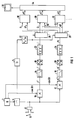
- a local oscillator 2 supplies a cosine signal with an angular frequency Q, from which a gate 4 with a repetition time Tr of e.g. 200 us periodically cuts out short transmission pulses of a few oscillation periods.
- the repetition time Tr is illustrated in FIG. 1 by block 5.
- a converter 6 converts the electrical transmission pulses into ultrasound pulses, which are emitted in predeterminable directions.
- the transducer 6 can be both an individual ultrasound transducer and an ultrasound transducer array with elementary transducers arranged in series.
- the transducer 6 After each transmission, the transducer 6 receives the particles 8 from interfaces and moving particles e.g. ultrasound signals reflected in a blood stream and converts them into electrical signals. These echo signals are each fed to two mixers 10 and 12. In the mixer 10, the echo signals are multiplied in a broadband manner by the cosine signal of the local oscillator 2 and in the mixer 12 by the sine signal of the local oscillator 2. The outputs of mixers 10 and 12 are connected to two demodulation low passes 14 and 16, respectively. The in-phase component i 'is available at the output of the demodulation low-pass filter 14 and the quadrature component q' of the complex envelope of the echo signal is available at the output of the demodulation low-pass filter 16.
- the demodulation low-pass filters allow the spectrum of the pulse envelope to pass through, but suppress the transmission frequency and higher harmonics thereof. They also represent the anti-aliasing filters for the following analog-to-digital conversion.
- the two quadrature components i 'and q' are digitally processed from here. For this purpose, they are each fed to an analog-digital converter 18 or 20.
- the quadrature components i 'and q' are digitized here at 6 MHz with a 12-bit output signal.
- the digital outputs of the analog-to-digital converters 18 and 20 are each connected to an input of a digital comb filter 22 and 24, respectively.
- the comb filters 22 and 24 contain blocking points at a distance of the pulse repetition frequency 1 / Tr.
- Such filters can be digitally implemented relatively elegantly (stationary canceller), in the simplest case the echo signals of two successive transmission pulses are subtracted from one another. Only the change signals remain.
- both the in-phase component i and the quadrature component q are each fed to a range gate 26 and 28, respectively.
- the area gates 26 and 28 distribute the signal sections corresponding to a certain depth to a respective Doppler evaluation circuit 30.
- the number of Doppler evaluation circuits 30 arranged in parallel thus corresponds to the number of depth ranges.
- the Doopler evaluation circuits 30 determine from the quadrature components from a depth range Az the average Doppler angular frequency of the moving particles in this depth range, e.g. B. in i1 and q1 the mean Doppler angular frequency " , 1.
- the signal sections for the first depth position are designated i1 and q1 for the second depth position i2 and q2 and for the third depth position i3 and q3.
- This can be followed by further depth ranges, but only three Doppler evaluation circuits 30 are shown here for reasons of clarity.
- the depths of the signal catchment areas are determined on the basis of a known sound velocity by the delay Tz and the opening duration ⁇ z of the area gates 26 and 28, which is illustrated by block 32.
- the values for the mean Doppler angular frequency " , 1, ⁇ d 2 ... at the outputs of the Doppler evaluation circuits 30 are now processed in accordance with the depth in a video signal circuit 34 so that they can be displayed on a screen 36 as a flow image in a sectional plane .
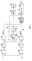
- the in-phase component i corresponding to a depth range is fed to a correlator 38.
- the correlator 38 forms the autocorrelation function Kii (Tr + t) of the in-phase component i of the echo signals of two successive transmission pulses in an environment of the pulse repetition time Tr, e.g. one and a half times the period T of the transmission frequency, i.e. Tr +/- 1.5T.
- the environment for the formation of the correlation function is limited by at least twice the pulse transit time, which a pulse needs to travel through the distance covered by a particle, the speed of which corresponds to the maximum speed to be measured.
- the in-phase component i and the quadrature component q of a signal catchment area are fed to a further correlator 40.
- the correlator 40 forms the cross-correlation function Kiq (Tr + t) of the in-phase component i and the quadrature component q of the echo signals of two successive transmission pulses in an environment of the pulse repetition time.
- the environment is defined here just like the environment of the autocorrelation function.
- the outputs of the correlators 38 and 40 are each connected to an averager 42 and 44, respectively.
- the averaging devices 42 and 44 average the correlation functions of 5 to 10 successive transmission shots.
- the mean value formers 42 and 44 are designed as summers. However, the sum is not divided by the number of values used for averaging. Their outputs are each connected to a selection circuit 46 or 48.
- the selection circuits 46 and 48 each select the value at the location of the pulse repetition time Tr from the correlation functions Kii and Kiq of the surrounding area. Both selected values are fed to a divider 50.
- the divider 50 forms the quotient of the cross-correlation function Kiq (Tr) and the autocorrelation function Kii (Tr).
- the output of the divider 50 is connected to an input 52 of an arctangent function circuit 54.
- the arctangent function circuit 54 thus fixes all possible values of the mean Doppler circle frequency multiplied by the pulse repetition time Tr.
- the averaged correlation function values Kii and Kiq of the mean value images 42 and 44 are fed to a displacement determination circuit which comprises a changeover switch 56.
- the changeover switch 56 is controlled as a function of the quotient from the divider 50 so that the shift of the maximum is determined in each case by the correlation function with the larger values. If the quotient is greater than one, that is to say the cross-correlation function Kiq is greater than the autocorrelation function Kii, then the cross-correlation function Kiq is examined for the position of its maximum. On the other hand, if the Quotient is less than one, the autocorrelation function Kii is examined for the position of its maximum. The changeover switch 56 forwards the correspondingly selected value to a maximum determination circuit 58.
- the shift in the maximum can be found by searching for the maximum of the function by comparing all the samples of the selected correlation function Kii or Kiq by means of a digital computer and determining the associated time shift in relation to the pulse repetition time Tr. Instead of the systematic search for the maximum among all samples, the zero of the derivative of the function can also be sought, whereby minima are to be excluded. Another possibility that can compensate for measurement errors as an integral method is known as the "center of gravity formula". Then the time shift At of the maximum results
- the area TB in which the correlation function is determined must, however, be chosen larger than in the other methods above when using the center of gravity formula.
- the Doppler angular frequency w results from the division of the arctangent value by the pulse repetition time Tr.
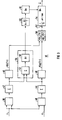
- the Doppler evaluation circuit 30 shown in FIG. 3 differs from the Doppler evaluation circuit 30 shown in FIG. 2 in that the changeover switch in FIG. 2 is replaced by an addition circuit 62. Both the autocorrelation function Kii (Tr + t) from the averager 42 and the cross-correlation function Kiq (Tr + t) from the averager 44 are fed to the addition circuit 62. The sum of the two correlation functions Kii (Tr + t) and Kiq (Tr + t) is now fed to the maximum determination circuit 58 for determining the time shift At. The use of the addition circuit avoids the question of which value of the correlation function Kii (Tr) or Kiq (Tr) is greatest at the point of the shift by the pulse repetition time Tr. The connection required in the Doppler evaluation circuit 30 according to FIG. 2 from the output of the divider 50 to the control input of the switch 56 is thus omitted in the Doppler evaluation circuit 30 according to FIG. 3.
- this technique can only be used together for a minimum of sixteen resolution cells due to the measurement-related errors. So you only get a clear statement for the mean value in an image field of approx. 1 cm 2. In this one you can, assuming that the measured value differences are not greater than the ambiguity range, form the mean value from the conventionally obtained values for all ambiguity ranges and treat the mean values as described so far, namely the smallest difference between the argument and the measure k.
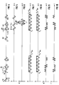
- FIG. 4 illustrates echo signals E1 and E2 in response to two successive transmission shots S1 and S2 from three point reflectors P1, P2, P3 in the time domain.
- a transmission signal consists of one Period T of a sine wave at intervals of the pulse repetition time Tr.
- the three reflectors P1, P2, P3 in FIG. 4 represent a large number of blood particles of a flow thread that has a speed component in the direction of sound. In reality, their echo signals are superimposed on one another and this superimposition changes over time because particles continuously leave the signal catchment area and others enter in a new position.
- the three signals shown here remain visible separately for didactic reasons. They do not change their assignment to one another, like the vast majority of the particles detected at the physiologically occurring speeds and the pulse repetition times Tr used in practice.
- the distances between the particles P1, P2 and P3 are chosen so that different phase positions to the transmission frequency occur. A change of particles with time is not shown.
- the second echo E2 of the same particle P1 reaches the transducer in response to the second transmission pulse S2 after the time T + At after the second transmission pulse S2.
- the same shift applies to the signals from the other point reflectors P2 and P3. 5 shows the first echo signal E1 shifted by the pulse repetition time Tr under the second echo signal E2 in FIG.
- the correlation of the second echo signal E2 is formed with the first echo signal E1 shifted in this way, and when the correlation is taken into account only power components of signals which come from the same particle - that is to say no cross power - then the correlation function according to FIG. 6 is obtained the shape of the autocorrelation of the transmission signal S1 or S2 represents, however, it is time-shifted by At.
- FIG. 7 shows the sinusoidal and FIG. 8 the cosine-shaped oscillator signal of the oscillator 2 shown in FIG. 1.
- the unfiltered mixed product echo signals E1 and E2 with the sinusoidal oscillator signal according to FIG. 7 is shown in FIG. It is designated by q "and is the output signal of the mixer 12 shown in FIG. 1.
- the unfiltered mixed product of the echo signals E1 and E2 with the cosine-shaped oscillator signal is shown in FIG. It is denoted by i "and occurs at the output of the mixer 10 shown in FIG. 1.
- the mixed products q "and i" of the first echo signal E1 shifted by the pulse repetition time Tr are shown in FIG. 11 and FIG. 12.
- FIGS. 13 to 16 show the different correlation functions of the unfiltered quadrature component i "and q" of two successive echo signals in an environment of the pulse repetition time Tr for the case of an infinitely long observation time (averaging, cross power component set to zero).
- FIG. 13 shows the autocorrelation function Kqq of the quadrature component q "and FIG. 14 shows the autocorrelation function Kii of the in-phase component i" of the echo signals E1 and E2 of two successive transmission pulses S1 and S2.
- the wave-shaped autocorrelation functions Kqq and Kii arise because the harmonics of the transmission oscillation have not been suppressed. Taking into account the low-pass filters 14 and 16 in FIG. 1, this would result in zero. This corresponds to a value of the arc tangent of + 90 or - 90 and the argument of the arc tangent of infinity or minus infinity.
- FIG. 15 shows the cross-correlation function Kqi and FIG. 15 shows the cross-correlation function Kiq of the quadrature component q "and the in-phase component i" of the echo signals E1 and E2.
- a triangular function as an envelope of the result of the direct correlations in changing correlations Kqq, Kii, Kqi or Kiq.
- the triangular function of the envelope is found in the correlation functions Kqi and Kiq at the speed of the point reflectors on which FIG. 13 to 16 are based.
- the same envelope results in the autocorrelation of the transmission signal.
- the shift in the maximum, here in the cross-correlation Kqi or Kiq according to FIG. 15 or 16 is a measure of the distance traveled by the moving particles between two transmission pulses S1 and S2 and thus a measure of the average speed of the particles under consideration.
- the ambiguities are removed without higher demands on the measuring accuracy.
- the measurement of the time shift from the demodulated signals fits well into the existing Doppler technology.
- the conventional Doppler technology is digitized at 6 MHz, so that the sampling frequency would only have to be doubled to determine the time shift At.
- the interface for digitization can be retained.
- Another possibility is that interpolation values are formed and processed from the already existing sampling.
- the interpolation method also has the following advantage: the low-frequency signal has high dynamics before the fixed target suppression by the digital comb filters 22 and 24 in FIG. This requires a large "bit depth" of the analog-to-digital converter 18, 20 in FIG. 1 during digitization. This can be done with a "slow" analog-to-digital converter of e.g. 6 MHz easier to implement than with a "fast” e.g. 15 MHz.
- the measuring range can only be formed for several resolution cells because this is the only way to achieve the necessary measuring time.
- This restriction does not apply to single-beam multi-port doublers, such as those used in internal medicine. Since, as described above, in practice the time shift At is very small compared to the width of the correlation functions, e.g. 6 times the transmission period is, it is difficult to distinguish between two flow threads of different speeds. That means a low speed resolution. This also applies to the case of opposite flow velocities, e.g. in swirling currents, the larger the signal catchment area, the more likely it is to occur.
- the method can therefore preferably be used in the case of a small signal catchment area, so that the probability of detecting very different speeds is small.
- a broadening of the envelope of the correlation functions according to FIGS. 13 to 16 is to be expected if many different speeds are recorded at the same time.
- the broadening can be understood as a measure of the flow swirl and can replace or supplement the measurement of the scatter of the Doppler spectrum for the areas k greater than 1/2, that is to say in the area of ambiguities. You either represent the correlation function yourself or form a measure for the broadening.
- the measurement of the broadening a can be done according to the following equations and ⁇ o is the "scattering" of the envelope of the autocorrelation function of the transmission pulse.
- the equations formally correspond to those for the evaluation of the Doppler spectrum. This measurement specification can be used here either for the function selected by the switch 60 or the sum of the two functions supplied by the addition circuit 62.
Landscapes
- Physics & Mathematics (AREA)
- Engineering & Computer Science (AREA)
- Acoustics & Sound (AREA)
- Multimedia (AREA)
- Aviation & Aerospace Engineering (AREA)
- General Physics & Mathematics (AREA)
- Ultra Sonic Daignosis Equipment (AREA)
- Radar Systems Or Details Thereof (AREA)
Claims (13)
caractérisé par le fait que
caractérisé par le fait que
Priority Applications (6)
| Application Number | Priority Date | Filing Date | Title |
|---|---|---|---|
| DE59008534T DE59008534D1 (de) | 1990-03-23 | 1990-03-23 | Verfahren und Vorrichtung zur Vermeidung von Mehrdeutigkeiten bei einem Pulsdopplergerät. |
| EP90105583A EP0447597B1 (fr) | 1990-03-23 | 1990-03-23 | Procédé et dispositif pour éviter les ambiguités dans un appareil doppler à impulsion |
| AT90105583T ATE118895T1 (de) | 1990-03-23 | 1990-03-23 | Verfahren und vorrichtung zur vermeidung von mehrdeutigkeiten bei einem pulsdopplergerät. |
| JP3080783A JPH04223273A (ja) | 1990-03-23 | 1991-03-18 | パルスドップラー装置における多義性回避方法および装置 |
| NO19911129A NO317914B1 (no) | 1990-03-23 | 1991-03-21 | Fremgangsmate til forhindring av flertydigheter ved et pulsdopplerapparat og pulsdopplerapparat til gjennomforing av fremgangsmaten |
| US07/673,029 US5081994A (en) | 1990-03-23 | 1991-03-21 | Method and apparatus for avoiding ambiguities in a pulse doppler apparatus |
Applications Claiming Priority (1)
| Application Number | Priority Date | Filing Date | Title |
|---|---|---|---|
| EP90105583A EP0447597B1 (fr) | 1990-03-23 | 1990-03-23 | Procédé et dispositif pour éviter les ambiguités dans un appareil doppler à impulsion |
Publications (2)
| Publication Number | Publication Date |
|---|---|
| EP0447597A1 EP0447597A1 (fr) | 1991-09-25 |
| EP0447597B1 true EP0447597B1 (fr) | 1995-02-22 |
Family
ID=8203802
Family Applications (1)
| Application Number | Title | Priority Date | Filing Date |
|---|---|---|---|
| EP90105583A Expired - Lifetime EP0447597B1 (fr) | 1990-03-23 | 1990-03-23 | Procédé et dispositif pour éviter les ambiguités dans un appareil doppler à impulsion |
Country Status (6)
| Country | Link |
|---|---|
| US (1) | US5081994A (fr) |
| EP (1) | EP0447597B1 (fr) |
| JP (1) | JPH04223273A (fr) |
| AT (1) | ATE118895T1 (fr) |
| DE (1) | DE59008534D1 (fr) |
| NO (1) | NO317914B1 (fr) |
Families Citing this family (7)
| Publication number | Priority date | Publication date | Assignee | Title |
|---|---|---|---|---|
| HRP940025A2 (en) * | 1994-01-14 | 1996-06-30 | Branko Breyer | A blood flow velocity measurement system perpendicular to a single probing beam |
| US5487387A (en) * | 1994-06-03 | 1996-01-30 | Duke University | Method and apparatus for distinguishing between solid masses and fluid-filled cysts |
| NO944736D0 (no) * | 1994-12-07 | 1994-12-07 | Vingmed Sound As | Fremgangsmåte for bestemmelse av blodhastighet |
| US5669386A (en) * | 1996-07-31 | 1997-09-23 | Hewlett-Packard Company | Ultrasonic flow measurement system employing cross-correlation of baseband reflection data |
| DE19740549C2 (de) * | 1997-09-15 | 2002-09-26 | Frank Obergrieser | Verfahren zur Messung der Strömungscharakteristik und anderer Prozeßparameter |
| RU2177159C1 (ru) * | 2000-12-29 | 2001-12-20 | Институт автоматики и электрометрии СО РАН | Следящий фильтр-процессор для обработки сигналов лазерного доплеровского измерителя скорости |
| WO2017015424A1 (fr) * | 2015-07-22 | 2017-01-26 | The University Of Mississippi | Capteur interférométrique différentiel multi-faisceaux laser et procédés pour une imagerie par vibration |
Family Cites Families (8)
| Publication number | Priority date | Publication date | Assignee | Title |
|---|---|---|---|---|
| FR2562675B1 (fr) * | 1984-04-06 | 1989-10-13 | Cgr Ultrasonic | Procede de levee d'ambiguite de la mesure par effet doppler de la vitesse d'un mobile |
| US4671294A (en) * | 1985-08-14 | 1987-06-09 | Hewlett-Packard Company | Pulsed doppler flow mapping apparatus |
| JPH0613031B2 (ja) * | 1987-08-12 | 1994-02-23 | 株式会社東芝 | 超音波血流イメ−ジング装置 |
| US4979513A (en) * | 1987-10-14 | 1990-12-25 | Matsushita Electric Industrial Co., Ltd. | Ultrasonic diagnostic apparatus |
| US4800891A (en) * | 1987-11-13 | 1989-01-31 | Siemens Medical Laboratories, Inc. | Doppler velocity processing method and apparatus |
| FR2629997B1 (fr) * | 1988-04-19 | 1990-08-17 | Labo Electronique Physique | Dispositif de mesure par correlation de la vitesse d'organes en mouvement et d'ecoulements sanguins |
| JPH01270859A (ja) * | 1988-04-22 | 1989-10-30 | Matsushita Electric Ind Co Ltd | 超音波ドップラ血流計および血流速度測定法 |
| US4995397A (en) * | 1988-09-30 | 1991-02-26 | Hitachi, Ltd. | Pulse doppler flow speed meter |
-
1990
- 1990-03-23 EP EP90105583A patent/EP0447597B1/fr not_active Expired - Lifetime
- 1990-03-23 DE DE59008534T patent/DE59008534D1/de not_active Expired - Lifetime
- 1990-03-23 AT AT90105583T patent/ATE118895T1/de not_active IP Right Cessation
-
1991
- 1991-03-18 JP JP3080783A patent/JPH04223273A/ja not_active Withdrawn
- 1991-03-21 US US07/673,029 patent/US5081994A/en not_active Expired - Lifetime
- 1991-03-21 NO NO19911129A patent/NO317914B1/no not_active IP Right Cessation
Also Published As
| Publication number | Publication date |
|---|---|
| US5081994A (en) | 1992-01-21 |
| NO911129D0 (no) | 1991-03-21 |
| DE59008534D1 (de) | 1995-03-30 |
| ATE118895T1 (de) | 1995-03-15 |
| NO317914B1 (no) | 2005-01-03 |
| NO911129L (no) | 1991-09-24 |
| JPH04223273A (ja) | 1992-08-13 |
| EP0447597A1 (fr) | 1991-09-25 |
Similar Documents
| Publication | Publication Date | Title |
|---|---|---|
| DE3687741T2 (de) | Geraet zur ultraschallechographie der bewegung von koerperorganen, insbesondere der blutstroemung oder des herzens. | |
| DE3431001C2 (fr) | ||
| DE2406630C2 (de) | Verfahren und Vorrichtung zur Durchflußgeschwindigkeitsmessung | |
| DE3785409T2 (de) | Vorrichtung zur Untersuchung von ortsveränderlichen Medien mittels Ultraschall-Echographie. | |
| DE68911797T2 (de) | Verfahren und Vorrichtung zur Fourier-Signalverarbeitung von gepulsten Doppler-Signalen. | |
| EP3161517B1 (fr) | Procédé de localisation d'objets au moyen d'un radar fmcw | |
| DE69720870T2 (de) | Verfahren und Vorrichtung zur Zielerfassung für Doppler Radargeräte mit Hilfe von breitbandigen eindeutigen Pulsen | |
| DE69118645T2 (de) | Ultraschall-Doppler-Durchflussmesser mit Diskriminierung der Gewebebewegung | |
| DE69219050T2 (de) | Ultraschalldiagnosegerät | |
| EP2841961B1 (fr) | Procédé et dispositif pour déterminer la distance et la vitesse radiale d'un objet au moyen de signaux radar | |
| EP1325350B2 (fr) | Procede et dispositif pour determiner l'eloignement d'un objet eloigne et la vitesse relative de celui-ci | |
| DE102008014786B4 (de) | Verfahren zur Bestimmung des Pegels eines Grundrauschens und Radar zur Anwendung des Verfahrens sowie eine Interferenzerfassungsvorrichtung | |
| DE69309335T2 (de) | Entfernungsmessung, Detektion und Auflösung in einem Radarsystem mit Verwendung von frequenzmodulierten Wellenformen mit mehrfachen Steilheiten | |
| DE69029211T2 (de) | Ultraschalldiagnosegerät zum Charakterisieren von Gewebe durch Analyse von Rückstreustrahlung | |
| DE3883484T2 (de) | Medizinisches Ultraschallabbildungssystem. | |
| DE19520920A1 (de) | Verfahren zum Bestimmen des Geschwindigkeit-Zeit-Spektrums einer Blutströmung | |
| DE102012220879A1 (de) | Rapid-Chirps-FMCW-Radar | |
| DE2542835A1 (de) | Verfahren und vorrichtung zur messung der geschwindigkeit eines objektives gegenueber einem bezugssystem | |
| DE19521856A1 (de) | Verfahren zur Durchführung einer winkelunabhängigen Doppler-Analyse bei Ultraschallabbildung | |
| DE69214023T2 (de) | Filter zur Festechounterdrückung für ein Ultraschalldopplersystem | |
| EP0447597B1 (fr) | Procédé et dispositif pour éviter les ambiguités dans un appareil doppler à impulsion | |
| DE1791191B2 (de) | Gerät zur Ermittlung der Blutflußge schwindigkeit | |
| DE3884547T2 (de) | Ultraschalldiagnostikgerät. | |
| EP3736601A1 (fr) | Détermination optoélectrique de la distance d'un objet en compte de bord de choc | |
| DE19545382A1 (de) | Verfahren zur Berechnung der Blutgeschwindigkeit und der Blutgeschwindigkeitsverteilung anhand mehrfach gegatterter Doppler-Signale |
Legal Events
| Date | Code | Title | Description |
|---|---|---|---|
| PUAI | Public reference made under article 153(3) epc to a published international application that has entered the european phase |
Free format text: ORIGINAL CODE: 0009012 |
|
| 17P | Request for examination filed |
Effective date: 19901205 |
|
| AK | Designated contracting states |
Kind code of ref document: A1 Designated state(s): AT CH DE FR GB LI NL |
|
| 17Q | First examination report despatched |
Effective date: 19931029 |
|
| GRAA | (expected) grant |
Free format text: ORIGINAL CODE: 0009210 |
|
| AK | Designated contracting states |
Kind code of ref document: B1 Designated state(s): AT CH DE FR GB LI NL |
|
| PG25 | Lapsed in a contracting state [announced via postgrant information from national office to epo] |
Ref country code: GB Effective date: 19950222 Ref country code: FR Effective date: 19950222 |
|
| REF | Corresponds to: |
Ref document number: 118895 Country of ref document: AT Date of ref document: 19950315 Kind code of ref document: T |
|
| REF | Corresponds to: |
Ref document number: 59008534 Country of ref document: DE Date of ref document: 19950330 |
|
| PGFP | Annual fee paid to national office [announced via postgrant information from national office to epo] |
Ref country code: CH Payment date: 19950614 Year of fee payment: 6 |
|
| EN | Fr: translation not filed | ||
| GBV | Gb: ep patent (uk) treated as always having been void in accordance with gb section 77(7)/1977 [no translation filed] |
Effective date: 19950222 |
|
| PLBE | No opposition filed within time limit |
Free format text: ORIGINAL CODE: 0009261 |
|
| STAA | Information on the status of an ep patent application or granted ep patent |
Free format text: STATUS: NO OPPOSITION FILED WITHIN TIME LIMIT |
|
| 26N | No opposition filed | ||
| PGFP | Annual fee paid to national office [announced via postgrant information from national office to epo] |
Ref country code: AT Payment date: 19960223 Year of fee payment: 7 |
|
| PGFP | Annual fee paid to national office [announced via postgrant information from national office to epo] |
Ref country code: NL Payment date: 19960328 Year of fee payment: 7 |
|
| PG25 | Lapsed in a contracting state [announced via postgrant information from national office to epo] |
Ref country code: LI Effective date: 19960331 Ref country code: CH Effective date: 19960331 |
|
| REG | Reference to a national code |
Ref country code: CH Ref legal event code: PL |
|
| PG25 | Lapsed in a contracting state [announced via postgrant information from national office to epo] |
Ref country code: AT Effective date: 19970323 |
|
| PG25 | Lapsed in a contracting state [announced via postgrant information from national office to epo] |
Ref country code: NL Effective date: 19971001 |
|
| NLV4 | Nl: lapsed or anulled due to non-payment of the annual fee |
Effective date: 19971001 |
|
| PGFP | Annual fee paid to national office [announced via postgrant information from national office to epo] |
Ref country code: DE Payment date: 20090518 Year of fee payment: 20 |
|
| PG25 | Lapsed in a contracting state [announced via postgrant information from national office to epo] |
Ref country code: DE Free format text: LAPSE BECAUSE OF EXPIRATION OF PROTECTION Effective date: 20100323 |