EP0447614A2 - Antenna duplexer - Google Patents
Antenna duplexer Download PDFInfo
- Publication number
- EP0447614A2 EP0447614A2 EP19900120627 EP90120627A EP0447614A2 EP 0447614 A2 EP0447614 A2 EP 0447614A2 EP 19900120627 EP19900120627 EP 19900120627 EP 90120627 A EP90120627 A EP 90120627A EP 0447614 A2 EP0447614 A2 EP 0447614A2
- Authority
- EP
- European Patent Office
- Prior art keywords
- antenna
- antenna switch
- radio
- receiver
- pass filter
- Prior art date
- Legal status (The legal status is an assumption and is not a legal conclusion. Google has not performed a legal analysis and makes no representation as to the accuracy of the status listed.)
- Granted
Links
- 230000005540 biological transmission Effects 0.000 claims description 16
- 238000010586 diagram Methods 0.000 abstract description 2
- 238000010276 construction Methods 0.000 description 1
Images

Classifications
-
- H—ELECTRICITY
- H04—ELECTRIC COMMUNICATION TECHNIQUE
- H04B—TRANSMISSION
- H04B1/00—Details of transmission systems, not covered by a single one of groups H04B3/00 - H04B13/00; Details of transmission systems not characterised by the medium used for transmission
- H04B1/06—Receivers
- H04B1/16—Circuits
- H04B1/18—Input circuits, e.g. for coupling to an antenna or a transmission line
-
- H—ELECTRICITY
- H01—ELECTRIC ELEMENTS
- H01Q—ANTENNAS, i.e. RADIO AERIALS
- H01Q1/00—Details of, or arrangements associated with, antennas
- H01Q1/27—Adaptation for use in or on movable bodies
- H01Q1/32—Adaptation for use in or on road or rail vehicles
-
- H—ELECTRICITY
- H01—ELECTRIC ELEMENTS
- H01Q—ANTENNAS, i.e. RADIO AERIALS
- H01Q23/00—Antennas with active circuits or circuit elements integrated within them or attached to them
-
- H—ELECTRICITY
- H04—ELECTRIC COMMUNICATION TECHNIQUE
- H04B—TRANSMISSION
- H04B1/00—Details of transmission systems, not covered by a single one of groups H04B3/00 - H04B13/00; Details of transmission systems not characterised by the medium used for transmission
- H04B1/38—Transceivers, i.e. devices in which transmitter and receiver form a structural unit and in which at least one part is used for functions of transmitting and receiving
- H04B1/40—Circuits
- H04B1/50—Circuits using different frequencies for the two directions of communication
Definitions
- the invention relates to an antenna switch according to the preamble of claim 1.
- Such an antenna switch is already known (Elektor, 1980, number 4, pages 59 to 61), with which a 27 MHz CB radio station installed in a vehicle and a car radio can be connected and operated to a common vehicle antenna.
- the known antenna switch has the disadvantage that it is not suitable as a passive antenna switch for connecting a portable radio frequency transmitter and receiver of low power, for example a hand-held walkie-talkie, instead of the CB radio station.
- the invention has for its object to develop an antenna switch according to the preamble of claim 1 such that it can be used to operate a car radio and a radio frequency transceiver of low power on a common antenna and that this antenna switch has a comparatively simple structure.
- FIG. 1 An embodiment of the invention is shown in the drawing using a single figure and is described in more detail below.
- the figure shows a block diagram of the antenna switch.
- 10 denotes a vehicle antenna for radio broadcast reception (for example LMKU) and for the transmission and reception of radio signals in a radio frequency range above the radio broadcast frequency range.
- radio broadcast reception for example LMKU
- the vehicle antenna 10 is connected to a first connection 11 of an active antenna switch 12.
- the first connection is followed by two parallel current branches 13 and 14, of which the first current branch 13 is a series circuit comprising a low-pass filter 15 and a first high-frequency amplifier 16, and the second current branch 14 is a series circuit comprising a high-pass filter 17, a filter 18 and a second high-frequency amplifier 19 and a switching device 20.
- the first high-frequency amplifier 16 is connected to a second connection 22, which is preferably a connector part
- the switching device 20 is connected to a third connection 23, which is preferably another connector part.
- the switching device 20 includes a switch 24 with which the second high-frequency amplifier 19 can be bridged.
- the construction stages 15 to 24 are preferably accommodated in a common shielding housing, which is indicated in the figure by dash-dotted lines 25.
- the connector part 22 corresponds to a connector part 26 which is connected to the antenna input of a car radio 27.
- the connector part 23 corresponds to a connector part 28 which is connected to the antenna connection of a radio transmission and reception device 29 of low transmission power, which is preferably a hand-held radio transmission and reception device.
- the hand-held radio transmitter and receiver 29 also has a connector part 30, which is connected, for example, via a fourth connector 31 in the form of a further connector part of the antenna switch 12 to the positive pole of a vehicle battery 32.
- the further connector part 31 is connected to power supply connections 33, 34 of the high-frequency amplifiers 19 and 16.
- Radio broadcast signals received with the vehicle antenna 10 reach the input of the first high-frequency amplifier 16 via the low-pass filter 15, the cut-off frequency of which is approximately 108 MHz, and are amplified in the latter and fed to the antenna input of the car radio 27 via the connector parts 22, 26.
- the low transmission energy compared to a motor vehicle radio transmitter and receiver causes the switching device 20 to respond and the switch 24 to be opened.
- the second high-frequency amplifier 19 thus amplifies the transmission signals of the hand-held radio transmission and reception device to a value that corresponds to the usual transmission power Motor vehicle radio transmission and reception device corresponds.
- the filter 18 passes the amplified high-frequency signals to the vehicle antenna 10 via the high-pass filter 17. In this case, the low-pass filter 15 keeps the transmission signals away from the first current branch 13.
- the power supply for the hand-held radio transmission and reception device 29 takes place when the hand-held radio transmission and reception device is used outside of the vehicle by a current source 35 contained in the device from the vehicle battery 32, the device preferably being detachably fastened in a mechanical holder which also receives the antenna switch 12. If the hand-held radio transceiver 29 is inserted into the holder, the connector parts 30, 31 provide the electrical connection to the vehicle battery 32 and the plug-in connector parts 23 and 28 provide the electrical connection from the antenna connection of the hand-held radio transceiver 29 to the switching device 20 forth.
Landscapes
- Engineering & Computer Science (AREA)
- Computer Networks & Wireless Communication (AREA)
- Signal Processing (AREA)
- Transceivers (AREA)
Abstract
2.1 Bekannte Antennenweichen, die den Betrieb eines Autoradios und eines Funksende- und -empfangsgerätes an einer gemeinsamen Fahrzeugantenne gestatten, sind nicht brauchbar, wenn das Funksende- und -empfangsgerät ein Handfunksende- und -empfangsgerät geringer Leistung ist.2.1 Known antenna switches, which allow the operation of a car radio and a radio transmitter and receiver on a common vehicle antenna, cannot be used if the radio transmitter and receiver is a low-power handheld transmitter and receiver.
2.2 Die erfindungsgemäße Antennenweiche (12) umfaßt zwei mit der Fahrzeugantenne (10) verbundene parallele Stromzweige (13, 14), von denen der eine (13) über ein Tiefpaßfilter (15) und einen ersten Hochfrequenzverstärker (16) mit dem Antenneneingang des Autoradios (27) verbunden ist. Der andere Stromzweig (14) enthält eine Reihenschaltung aus einem Hochpaßfilter (17), einem zweiten Hochfrequenzverstärker (19) und einer Schaltvorrichtung (20), die mit einem Antennenanschluß des Funksende- und -empfangsgerätes (29) lösbar verbindbar ist.2.2 The antenna switch (12) according to the invention comprises two parallel current branches (13, 14) connected to the vehicle antenna (10), one of which (13) via a low-pass filter (15) and a first high-frequency amplifier (16) to the antenna input of the car radio ( 27) is connected. The other current branch (14) contains a series circuit comprising a high-pass filter (17), a second high-frequency amplifier (19) and a switching device (20) which can be detachably connected to an antenna connection of the radio transmitter and receiver (29).
2.3 Ein bevorzugtes Anwendungsgebiet für die Antennenweiche ist der Betrieb eines Autoradios und eines Handsprechfunkgerätes geringer Leistung an einer gemeinsamen Antenne eines Kraftfahrzeuges.2.3 A preferred area of application for the antenna switch is the operation of a car radio and a low-power handheld radio on a common antenna of a motor vehicle.
3. Die Zeichnung zeigt ein Blockschaltbild der Antennenweiche.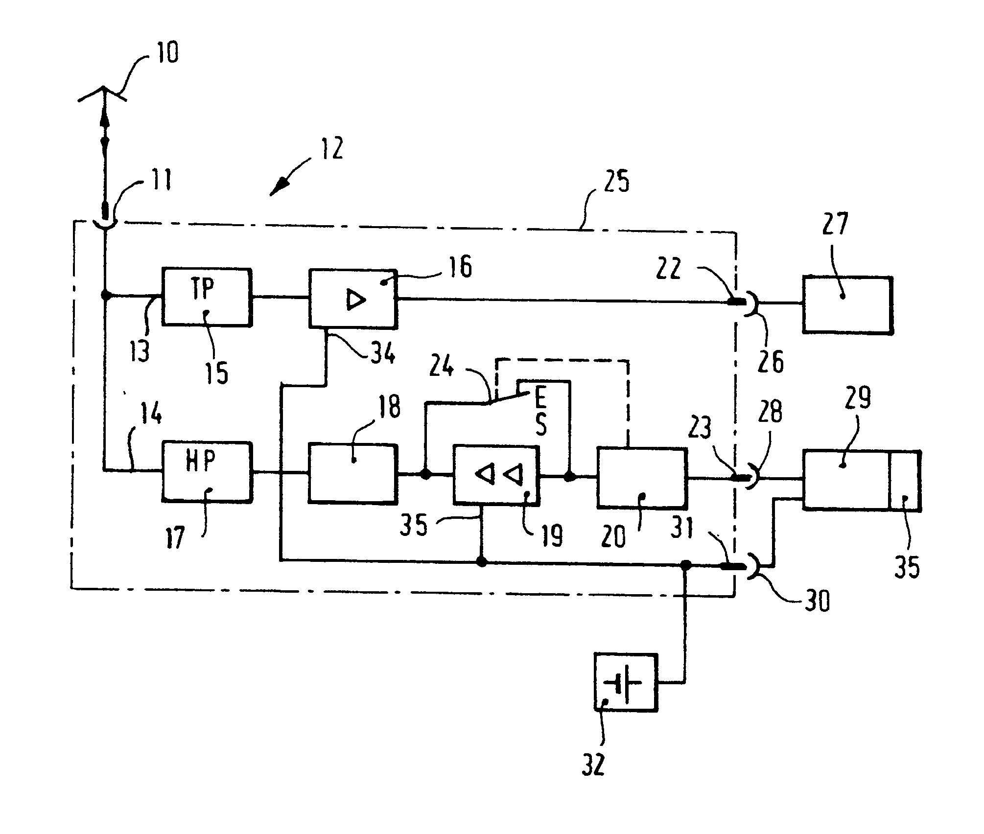
Description
Die Erfindung betrifft eine Antennenweiche nach dem Oberbegriff des Anspruchs 1.The invention relates to an antenna switch according to the preamble of claim 1.
Es ist schon eine derartige Antennenweiche bekannt (Elektor, 1980, Heft 4, Seiten 59 bis 61), mit welcher eine in einem Fahrzeug eingebaute 27-MHz-CB-Funkstation und ein Autoradio an eine gemeinsame Fahrzeugantenne angeschlossen und betrieben werden können. Die bekannte Antennenweiche hat den Nachteil, daß sie als passive Antennenweiche nicht für den Anschluß eines tragbaren Hochfrequenzsende- und -empfangsgerätes geringer Leistung, also zum Beispiel eines in der Hand zu-haltenden Handsprechfunkgerätes, anstelle der CB-Funkstation geeignet ist.Such an antenna switch is already known (Elektor, 1980, number 4, pages 59 to 61), with which a 27 MHz CB radio station installed in a vehicle and a car radio can be connected and operated to a common vehicle antenna. The known antenna switch has the disadvantage that it is not suitable as a passive antenna switch for connecting a portable radio frequency transmitter and receiver of low power, for example a hand-held walkie-talkie, instead of the CB radio station.
Der Erfindung liegt die Aufgabe zugrunde, eine Antennenweiche gemäß dem Oberbegriff des Anspruchs 1 derart weiterzubilden, daß mit ihr ein Autoradio und ein Hochfrequenzsende- und -empfangsgerät kleiner Leistung an einer gemeinsamen Antenne betrieben werden können und daß diese Antennenweiche einen vergleichsweise einfachen Aufbau hat.The invention has for its object to develop an antenna switch according to the preamble of claim 1 such that it can be used to operate a car radio and a radio frequency transceiver of low power on a common antenna and that this antenna switch has a comparatively simple structure.
Ein Ausführungsbeispiel der Erfindung ist in der Zeichnung anhand einer einzigen Figur dargestellt und wird im folgenden näher beschrieben. Die Figur zeigt ein Blockschaltbild der Antennenweiche.An embodiment of the invention is shown in the drawing using a single figure and is described in more detail below. The figure shows a block diagram of the antenna switch.
In der Figur bezeichnet 10 eine Fahrzeugantenne für den Hörrundfunkempfang (zum Beispiel LMKU) und für das Senden und Empfangen von Funksignalen in einem oberhalb des Hörrundfunk-Frequenzbereiches liegenden Funkfrequenzbereich.In the figure, 10 denotes a vehicle antenna for radio broadcast reception (for example LMKU) and for the transmission and reception of radio signals in a radio frequency range above the radio broadcast frequency range.
Die Fahrzeugantenne 10 ist mit einem ersten Anschluß 11 einer aktiven Antennenweiche 12 verbunden. An den ersten Anschluß schließen sich zwei parallele Stromzweige 13 und 14 an, von denen der erste Stromzweig 13 eine Reihenschaltung aus einem Tiefpaßfilter 15 und einem ersten Hochfrequenzverstärker 16 und der zweite Stromzweig 14 eine Reihenschaltung aus einem Hochpaßfilter 17, einem Filter 18, einem zweiten Hochfrequenzverstärker 19 und einer Schaltvorrichtung 20 aufweist. Der erste Hochfrequenzverstärker 16 ist mit einem zweiten Anschluß 22, das ist vorzugsweise ein Steckverbinderteil, und die Schaltvorrichtung 20 mit einem dritten Anschluß 23, das ist vorzugsweise ein weiteres Steckverbinderteil, verbunden. Zu der Schaltvorrichtung 20 gehört ein Schalter 24, mit dem der zweite Hochfrequenzverstärker 19 überbrückt werden kann.The
Die Baustufen 15 bis 24 sind vorzugsweise in einem gemeinsamen Abschirmgehäuse untergebracht, das in der Figur durch strichpunktierte Linien 25 angedeutet ist.The
Das Steckverbinderteil 22 korrespondiert mit einem Steckverbinderteil 26, welches mit dem Antenneneingang eines Autoradios 27 verbunden ist. Das Steckverbinderteil 23 korrespondiert mit einem Steckverbinderteil 28, welches mit dem Antennenanschluß eines Funksende- und -empfangsgerätes 29 geringer Sendeleistung, das ist vorzugsweise ein Handfunksende- und -empfangsgerät, verbunden ist.The
Das Handfunksende- und -empfangsgerät 29 weist noch ein Steckverbinderteil 30 auf, das beispielsweise über einen vierten Anschluß 31 in Form eines weiteren Steckverbinderteils der Antennenweiche 12 mit dem Pluspol einer Fahrzeugbatterie 32 verbunden ist. Das weitere Steckverbinderteil 31 steht mit Stromversorgungsanschlüssen 33, 34 der Hochfrequenzverstärker 19 und 16 in Verbindung.The hand-held radio transmitter and
Die Wirkungsweise der vorstehend beschriebenen Antennenweiche ist folgende.The operation of the antenna switch described above is as follows.
Mit der Fahrzeugantenne 10 empfangene Hörrundfunksignale gelangen über das Tiefpaßfilter 15, dessen Grenzfrequenz bei etwa 108 MHz liegt, an den Eingang des ersten Hochfrequenzverstärkers 16 und werden in diesem verstärkt und über die Steckverbinderteile 22, 26 dem Antenneneingang des Autoradios 27 zugeführt. Das Hochpaßfilter 17, dessen Grenzfrequenz ebenfalls bei etwa 108 MHz liegt, verhindert, daß die Hörrundfunksignale den zweiten Stromweg 14 passieren.Radio broadcast signals received with the
Mit der Fahrzeugantenne 10 aufgenommene Funkempfangssignale, die zum Beispiel in einem Frequenzbereich von 400 MHz liegen, werden durch das Tiefpaßfilter 15 von dem ersten Stromzweig 13 ferngehalten. Diese Signale gelangen über das Hochpaßfilter 17 und das Filter 18, das zur Verhinderung von Interkanalmodulationsstörungen vorgesehen ist, unter Umgehung des zweiten Hochfrequenzverstärkers 19 - der Schalter 24 ist bei Empfangsbetrieb des Handfunksende- und -empfangsgerätes 29 geschlossen - über die Schaltvorrichtung 20 und die Steckverbinderteile 23 und 28 an den Antennenanschluß des Handfunksende- und -empfangsgerätes 29.Radio reception signals recorded with the
Wird das Handfunksende- und -empfangsgerät 29 auf Senden geschaltet, dann bewirkt die im Vergleich zu einem Kraftfahrzeugfunksende- und -empfangsgerät geringe Sendeenergie, daß die Schaltvorrichtung 20 anspricht und der Schalter 24 geöffnet wird. Damit verstärkt der zweite Hochfrequenzverstärker 19 die Sendesignale des Handfunksende- und -empfangsgerätes auf einen Wert, der der üblichen Sendeleistung eines Kraftfahrzeugfunksende- und -empfangsgerätes entspricht. Das Filter 18 leitet die verstärkten Hochfrequenzsignale über das Hochpaßfilter 17 an die Fahrzeugantenne 10. In diesem Fall hält das Tiefpaßfilter 15 die Sendesignale von dem ersten Stromzweig 13 fern.If the hand-held radio transmitter and
Die Stromversorgung für das Handfunksende- und -empfangsgerät 29 erfolgt bei außerhalb des Fahrzeuges verwendetem Handfunksende- und -empfangsgerät durch eine in dem Gerät enthaltene Stromquelle 35. Bei in dem Fahrzeug betriebenem Handfunksende- und -empfangsgerät erfolgt dessen Stromversorgung vorzugsweise unter Abschaltung der internen Stromquelle 35 aus der Fahrzeugbatterie 32, wobei das Gerät vorzugsweise in einer mechanischen Halterung, die auch die Antennenweiche 12 aufnimmt, lösbar befestigt ist. Wird das Handfunksende- und -empfangsgerät 29 in die Halterung eingeschoben, so stellen die Steckverbinderteile 30, 31 die elektrische Verbindung zu der Fahrzeugbatterie 32 und die Steckverbinderteile 23 und 28 die elektrische Verbindung von dem Antennenanschluß des Handfunksende- und -empfangsgerätes 29 zu der Schaltvorrichtung 20 her.The power supply for the hand-held radio transmission and
Claims (6)
Applications Claiming Priority (2)
| Application Number | Priority Date | Filing Date | Title |
|---|---|---|---|
| DE4008632A DE4008632C2 (en) | 1990-03-17 | 1990-03-17 | Antenna switch |
| DE4008632 | 1990-03-17 |
Publications (3)
| Publication Number | Publication Date |
|---|---|
| EP0447614A2 true EP0447614A2 (en) | 1991-09-25 |
| EP0447614A3 EP0447614A3 (en) | 1992-08-12 |
| EP0447614B1 EP0447614B1 (en) | 1995-10-04 |
Family
ID=6402459
Family Applications (1)
| Application Number | Title | Priority Date | Filing Date |
|---|---|---|---|
| EP90120627A Expired - Lifetime EP0447614B1 (en) | 1990-03-17 | 1990-10-27 | Antenna duplexer |
Country Status (4)
| Country | Link |
|---|---|
| US (1) | US5239688A (en) |
| EP (1) | EP0447614B1 (en) |
| DE (2) | DE4008632C2 (en) |
| DK (1) | DK0447614T3 (en) |
Cited By (3)
| Publication number | Priority date | Publication date | Assignee | Title |
|---|---|---|---|---|
| EP0782213A3 (en) * | 1995-12-18 | 1997-07-30 | Siemens Aktiengesellschaft | Radio station with a separate antenna unit |
| DE19644648C1 (en) * | 1996-10-26 | 1998-05-20 | Bosch Gmbh Robert | Radio receiver |
| DE10003704A1 (en) * | 2000-01-28 | 2001-08-09 | Infineon Technologies Ag | Circuit arrangement with bandpass filters |
Families Citing this family (11)
| Publication number | Priority date | Publication date | Assignee | Title |
|---|---|---|---|---|
| JPH07246915A (en) * | 1994-03-10 | 1995-09-26 | Alpine Electron Inc | On-vehicle receiving device |
| US5541980A (en) * | 1994-10-27 | 1996-07-30 | Cobra Electronics Corporation | Cordless telephone/radio-monitoring system |
| DE19742346C2 (en) * | 1997-09-25 | 2002-12-05 | Siemens Ag | Arrangement and method for preamplifying received signals for a radio station |
| JPH11154804A (en) * | 1997-11-20 | 1999-06-08 | Hitachi Ltd | High frequency circuit device |
| WO2001095507A2 (en) * | 2000-06-09 | 2001-12-13 | Daimlerchrysler Ag | Arrangement for operating various terminal devices |
| DE102006021514A1 (en) * | 2006-05-04 | 2007-11-15 | Funkwerk Dabendorf Gmbh | Arrangement for transmitting signals via an antenna feed line in a mobile radio subscriber station |
| US20070281626A1 (en) * | 2006-06-05 | 2007-12-06 | Dobosz Paul J | Vehicle telematics satellite data transceiver utilizing fm radio circuitry |
| DE102007010888B4 (en) * | 2007-03-06 | 2010-03-04 | Continental Automotive Gmbh | Control unit for wireless communication with a peripheral unit |
| CN102420623B (en) * | 2011-08-26 | 2014-11-05 | 奇瑞汽车股份有限公司 | Transmission method for power supply signals and radiogram radio-frequency signals as well as antenna amplifier |
| CN104331720A (en) * | 2014-10-24 | 2015-02-04 | 厦门信达物联科技有限公司 | Multichannel ultrahigh radio frequency identification system |
| US12107644B1 (en) * | 2021-02-10 | 2024-10-01 | Liam Gunter | Interface for power and data exchange with sensors system |
Family Cites Families (8)
| Publication number | Priority date | Publication date | Assignee | Title |
|---|---|---|---|---|
| DE2167276C2 (en) * | 1971-03-31 | 1984-04-26 | Gerhard Prof. Dr.-Ing. 8012 Ottobrunn Flachenecker | Active Unipol receiving antenna for reception in two frequency ranges separated by a frequency gap |
| DE2153630C3 (en) * | 1971-10-27 | 1980-06-19 | Standard Elektrik Lorenz Ag, 7000 Stuttgart | Circuit arrangement for switching the transmission direction for a transmitter and a receiver |
| US4037177A (en) * | 1976-03-03 | 1977-07-19 | Tyrey Elasco A | Radio-frequency coupler |
| US4106025A (en) * | 1976-10-22 | 1978-08-08 | Sidney Katz | Coupling converter for vehicle antennas |
| US4525863A (en) * | 1983-10-19 | 1985-06-25 | Gte Laboratories Incorporated | Solid state transmit/receive switch |
| US4850034A (en) * | 1987-08-27 | 1989-07-18 | Campbell Mark E | Method and apparatus for installing a cellular telephone in a vehicle |
| DE3844541C2 (en) * | 1987-09-30 | 1995-06-08 | Fujitsu Ten Ltd | Antenna circuit for a multiband antenna |
| DE3802810A1 (en) * | 1988-01-30 | 1989-08-03 | Bosch Gmbh Robert | Active frequency diplexer |
-
1990
- 1990-03-17 DE DE4008632A patent/DE4008632C2/en not_active Expired - Fee Related
- 1990-10-27 DK DK90120627.6T patent/DK0447614T3/en active
- 1990-10-27 DE DE59009746T patent/DE59009746D1/en not_active Expired - Fee Related
- 1990-10-27 EP EP90120627A patent/EP0447614B1/en not_active Expired - Lifetime
-
1991
- 1991-01-30 US US07/647,912 patent/US5239688A/en not_active Expired - Lifetime
Cited By (3)
| Publication number | Priority date | Publication date | Assignee | Title |
|---|---|---|---|---|
| EP0782213A3 (en) * | 1995-12-18 | 1997-07-30 | Siemens Aktiengesellschaft | Radio station with a separate antenna unit |
| DE19644648C1 (en) * | 1996-10-26 | 1998-05-20 | Bosch Gmbh Robert | Radio receiver |
| DE10003704A1 (en) * | 2000-01-28 | 2001-08-09 | Infineon Technologies Ag | Circuit arrangement with bandpass filters |
Also Published As
| Publication number | Publication date |
|---|---|
| DE59009746D1 (en) | 1995-11-09 |
| DK0447614T3 (en) | 1995-12-27 |
| EP0447614A3 (en) | 1992-08-12 |
| DE4008632C2 (en) | 1994-05-19 |
| US5239688A (en) | 1993-08-24 |
| EP0447614B1 (en) | 1995-10-04 |
| DE4008632A1 (en) | 1991-09-19 |
Similar Documents
| Publication | Publication Date | Title |
|---|---|---|
| EP0806849B1 (en) | Circuit arrangement for performance check of mobile broadcast reception systems | |
| DE69623199T2 (en) | High frequency circuit for a portable radio | |
| DE4008632C2 (en) | Antenna switch | |
| DE69821186T2 (en) | Dual band transmitter with switchable adjustment circuit | |
| DE4409382A1 (en) | Digital mobile radio | |
| EP1168500A2 (en) | Antenna switch for a mobile transceiver | |
| EP1371144B1 (en) | Circuit arrangement for compensation of the damping in an antenna feed cable for a mobile radio device | |
| DE69431218T2 (en) | Procedure for operating a radio telephone | |
| DE19547288C2 (en) | Radio station with a remote antenna unit | |
| EP1295402B1 (en) | Arrangement for operating various terminal devices | |
| DE69126675T2 (en) | Handheld walkie-talkie in modular design | |
| DE19913064C1 (en) | Circuit arrangement for damping compensation | |
| EP0419711B1 (en) | Interface module for coupling modulated signals thereto | |
| DE19635175A1 (en) | Telecommunication device with a switching device designed as a ring circuit | |
| DE69030784T2 (en) | Telephone handset acting as an independent unit | |
| DE3633726C2 (en) | ||
| DE2339705C2 (en) | Fault location system for line amplifiers of amplifier points in a transmission line | |
| EP1371143B1 (en) | Circuit arrangement for compensation of the damping in an antenna feed cable for a mobile radio device | |
| DE68919334T2 (en) | Two-part radio telephone. | |
| DE29501275U1 (en) | Transmitting / receiving arrangement for mobile radio | |
| DE19514993A1 (en) | Bidirectional aerial amplifier for telecommunication signals | |
| DE19948964C2 (en) | Circuit arrangement for establishing a unidirectional connection between transmitting and / or receiving devices and an antenna | |
| DE102005044620B4 (en) | Front end module for wireless communication | |
| DE2809751C2 (en) | Channel filter for use in a carrier frequency system | |
| DE102010045244A1 (en) | Circuit arrangement for compensating attenuation in radio frequency line between e.g. mobile telephone and antenna of vehicle, has reception and transmission paths with common portion for guiding radio signals in same direction |
Legal Events
| Date | Code | Title | Description |
|---|---|---|---|
| PUAI | Public reference made under article 153(3) epc to a published international application that has entered the european phase |
Free format text: ORIGINAL CODE: 0009012 |
|
| AK | Designated contracting states |
Kind code of ref document: A2 Designated state(s): CH DE DK FR GB IT LI SE |
|
| RAP3 | Party data changed (applicant data changed or rights of an application transferred) |
Owner name: ROBERT BOSCH GMBH |
|
| PUAL | Search report despatched |
Free format text: ORIGINAL CODE: 0009013 |
|
| AK | Designated contracting states |
Kind code of ref document: A3 Designated state(s): CH DE DK FR GB IT LI SE |
|
| 17P | Request for examination filed |
Effective date: 19930122 |
|
| 17Q | First examination report despatched |
Effective date: 19940502 |
|
| GRAA | (expected) grant |
Free format text: ORIGINAL CODE: 0009210 |
|
| AK | Designated contracting states |
Kind code of ref document: B1 Designated state(s): CH DE DK FR GB IT LI SE |
|
| ET | Fr: translation filed | ||
| REF | Corresponds to: |
Ref document number: 59009746 Country of ref document: DE Date of ref document: 19951109 |
|
| ITF | It: translation for a ep patent filed | ||
| REG | Reference to a national code |
Ref country code: DK Ref legal event code: T3 |
|
| GBT | Gb: translation of ep patent filed (gb section 77(6)(a)/1977) |
Effective date: 19951216 |
|
| PLBE | No opposition filed within time limit |
Free format text: ORIGINAL CODE: 0009261 |
|
| STAA | Information on the status of an ep patent application or granted ep patent |
Free format text: STATUS: NO OPPOSITION FILED WITHIN TIME LIMIT |
|
| 26N | No opposition filed | ||
| REG | Reference to a national code |
Ref country code: GB Ref legal event code: IF02 |
|
| PGFP | Annual fee paid to national office [announced via postgrant information from national office to epo] |
Ref country code: GB Payment date: 20030930 Year of fee payment: 14 |
|
| PGFP | Annual fee paid to national office [announced via postgrant information from national office to epo] |
Ref country code: DK Payment date: 20031021 Year of fee payment: 14 |
|
| PGFP | Annual fee paid to national office [announced via postgrant information from national office to epo] |
Ref country code: SE Payment date: 20031022 Year of fee payment: 14 |
|
| PGFP | Annual fee paid to national office [announced via postgrant information from national office to epo] |
Ref country code: CH Payment date: 20031024 Year of fee payment: 14 |
|
| PG25 | Lapsed in a contracting state [announced via postgrant information from national office to epo] |
Ref country code: GB Free format text: LAPSE BECAUSE OF NON-PAYMENT OF DUE FEES Effective date: 20041027 |
|
| PG25 | Lapsed in a contracting state [announced via postgrant information from national office to epo] |
Ref country code: SE Free format text: LAPSE BECAUSE OF NON-PAYMENT OF DUE FEES Effective date: 20041028 |
|
| PG25 | Lapsed in a contracting state [announced via postgrant information from national office to epo] |
Ref country code: CH Free format text: LAPSE BECAUSE OF NON-PAYMENT OF DUE FEES Effective date: 20041031 Ref country code: LI Free format text: LAPSE BECAUSE OF NON-PAYMENT OF DUE FEES Effective date: 20041031 |
|
| PG25 | Lapsed in a contracting state [announced via postgrant information from national office to epo] |
Ref country code: DK Free format text: LAPSE BECAUSE OF NON-PAYMENT OF DUE FEES Effective date: 20041101 |
|
| EUG | Se: european patent has lapsed | ||
| REG | Reference to a national code |
Ref country code: DK Ref legal event code: EBP |
|
| GBPC | Gb: european patent ceased through non-payment of renewal fee |
Effective date: 20041027 |
|
| REG | Reference to a national code |
Ref country code: CH Ref legal event code: PL |
|
| PG25 | Lapsed in a contracting state [announced via postgrant information from national office to epo] |
Ref country code: IT Free format text: LAPSE BECAUSE OF NON-PAYMENT OF DUE FEES Effective date: 20051027 |
|
| PGFP | Annual fee paid to national office [announced via postgrant information from national office to epo] |
Ref country code: FR Payment date: 20081021 Year of fee payment: 19 |
|
| PGFP | Annual fee paid to national office [announced via postgrant information from national office to epo] |
Ref country code: DE Payment date: 20081222 Year of fee payment: 19 |
|
| REG | Reference to a national code |
Ref country code: FR Ref legal event code: ST Effective date: 20100630 |
|
| PG25 | Lapsed in a contracting state [announced via postgrant information from national office to epo] |
Ref country code: FR Free format text: LAPSE BECAUSE OF NON-PAYMENT OF DUE FEES Effective date: 20091102 Ref country code: DE Free format text: LAPSE BECAUSE OF NON-PAYMENT OF DUE FEES Effective date: 20100501 |