EP0447634A2 - Dispositif doseur-dispenseur pour fluides - Google Patents
Dispositif doseur-dispenseur pour fluides Download PDFInfo
- Publication number
- EP0447634A2 EP0447634A2 EP90123505A EP90123505A EP0447634A2 EP 0447634 A2 EP0447634 A2 EP 0447634A2 EP 90123505 A EP90123505 A EP 90123505A EP 90123505 A EP90123505 A EP 90123505A EP 0447634 A2 EP0447634 A2 EP 0447634A2
- Authority
- EP
- European Patent Office
- Prior art keywords
- upper chamber
- chamber
- particular according
- pouring
- wall
- Prior art date
- Legal status (The legal status is an assumption and is not a legal conclusion. Google has not performed a legal analysis and makes no representation as to the accuracy of the status listed.)
- Granted
Links
Images


Classifications
-
- G—PHYSICS
- G01—MEASURING; TESTING
- G01F—MEASURING VOLUME, VOLUME FLOW, MASS FLOW OR LIQUID LEVEL; METERING BY VOLUME
- G01F11/00—Apparatus requiring external operation adapted at each repeated and identical operation to measure and separate a predetermined volume of fluid or fluent solid material from a supply or container, without regard to weight, and to deliver it
- G01F11/10—Apparatus requiring external operation adapted at each repeated and identical operation to measure and separate a predetermined volume of fluid or fluent solid material from a supply or container, without regard to weight, and to deliver it with measuring chambers moved during operation
- G01F11/26—Apparatus requiring external operation adapted at each repeated and identical operation to measure and separate a predetermined volume of fluid or fluent solid material from a supply or container, without regard to weight, and to deliver it with measuring chambers moved during operation wherein the measuring chamber is filled and emptied by tilting or inverting the supply vessel, e.g. bottle-emptying apparatus
- G01F11/262—Apparatus requiring external operation adapted at each repeated and identical operation to measure and separate a predetermined volume of fluid or fluent solid material from a supply or container, without regard to weight, and to deliver it with measuring chambers moved during operation wherein the measuring chamber is filled and emptied by tilting or inverting the supply vessel, e.g. bottle-emptying apparatus for liquid or semi-liquid
Definitions
- the invention relates to a device for the metered dispensing of liquid according to the features of the preamble of patent claim 1.
- a device of this type is known from EP-PS 0 132 628.
- the metered dispensing takes place through a muzzle pipe that goes into the low position; it only arises on the second turn.
- the device formed by a pot-shaped housing is divided into an upper chamber and a lower-lying pouring chamber by means of an essentially transverse dividing wall.
- the pouring chamber and the upper chamber are connected to each other via a flow hole.
- the supply takes place via an inlet opening in the upper chamber.
- the mouth pipe ends above the partition wall.
- An air passage is also formed in the upper chamber.
- the pouring spout extends almost to the bottom of a cup surrounding the pouring chamber, leaving the required flow path. This leads to a double-walled construction and thus increases the cost of the device, which can be described as a typical mass article.
- the injection mold is also relatively complicated.
- the object of the present invention is to design a generic device in a more advantageous manner in terms of production technology, while maintaining or even increasing the metering accuracy.
- the invention proposes that the mouth pipe is attached to the upper chamber and that the pouring chamber can be snap-connected to the upper chamber. Except for the slight overlap zone of the snap connection, double walls are avoided.
- the corresponding two-part system also has advantages with regard to the spraying process.
- the opposite accessibility of the cores also allows a structure that is optimal in terms of flow technology to be achieved.
- the invention further proposes that the muzzle tube is formed in one piece with the upper chamber. This also supports the goal of saving material. In addition, there is a stable transition in the connection area between the muzzle tube and the housing of the device. Further it turns out to be advantageous that ventilation holes are formed in the side wall of the upper chamber. The ventilation holes provided in the majority avoid any weakening of the side wall. The fact that the ventilation holes are formed approximately halfway up the side wall of the upper chamber results in a rapid flooding with evacuation of the air. It is also proposed that three ventilation holes are arranged side by side. Side by side means lying at the same height and in the area next to the theoretical tipping level. As a result, there is no need for meticulous observance of the said level.
- an inlet channel leading to the inlet openings is formed by an indentation of the side wall of the upper chamber to interact with a neck of the storage container.
- the corresponding indentation can be taken into account in terms of shape without difficulty, since it is open to the outside and extends essentially in the axial direction of the pot-shaped housing.
- the pot can at least partially rest on the neck or extend radially spaced apart from it. In the latter case there would be lateral inlet areas to the actual inlet channel, also here to support the benefit of not having to work exactly in the theoretical tilting plane of the device.
- the inlet openings open in a plane which is formed by the upper edge of the upper chamber.
- the inlet openings and ventilation holes are axially quite far apart; Inlet openings and ventilation holes are usually on diametrically opposite sides.
- the ceiling of the upper chamber is formed by a screw cap, which is penetrated by the muzzle tube in tight contact.
- the multi-part structure that is also available in this way allows for seal-specific ones To be able to meet requirements particularly cheaply by making one component "softer” accordingly.
- the sealing system can also be reached here by bouncing.
- an orientation projection is arranged on the muzzle tube for cooperation with an orientation recess of the screw cap. This has advantages in terms of assembly technology, especially with regard to foolproof assignment of the parts to one another.
- orientation sword it is expediently an axially extending orientation sword.
- the latter can extend practically over the entire length of the muzzle tube. It also acts as a stabilizing rib.
- early formation of the screw cap and housing can be achieved by forming a fairly long orientation sword.
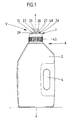
- the device V according to the invention is placed on the neck 1 of a storage container 2.
- the liquid to be dispensed in measured quantities therefrom bears the reference number 3.
- the storage container 2 forms a gripping cavity 4.
- the latter is located externally to the longitudinal central axis x-x of the device V and thus compulsorily maintains a certain tilting direction of the whole.
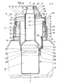
- the corresponding casting plane coincides with the section in FIG. 4 and is designated E-E in FIG. 7.
- the lateral gripping opening 4 creates a bridge-shaped handle.
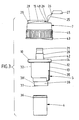
- the device V shown consists of three separately manufactured components, namely a pot-shaped housing 5, a cup 6 and a screw cap 7.
- Housing 5 and cup 6 consist of HDPE (hard polyethylene), the screw cap 7 made of PP (polypropylene).
- the cup-shaped housing 5 is suspended in the substantially cylindrical cavity 8 of the neck 1 across the edges.
- the relevant front edge of the neck 1 bears the reference number 9.
- an outwardly directed housing edge 10 forms a downwardly open, bottom-side, sealing and clamping plug groove 11.
- the inner ring wall 12 of said plug groove 11 lifts from the outer surface of the Side wall 13 of the housing 5. It is therefore particularly flexible.
- the screw cap 7 With its cover 15, the screw cap 7 forms the upper end of an upper chamber I, namely at a clearly axial distance from the end edge 9 or housing edge 10.
- a pouring chamber II Below the upper chamber I is a pouring chamber II.
- This lower-lying pouring chamber which is arranged coaxially to the chamber I, is spatially separated but fluidically connected via a partition wall 16 which runs essentially transversely to the longitudinal central axis x-x of the device V.
- the corresponding connection creates a laterally lying, relatively large flow hole 17 in the region of the annular bottom 18 of the housing 5.
- the dome-shaped dividing wall 16 more precisely implemented as a funnel, is consequently broken through.
- the funnel wall, i. H. the partition wall 16 extends at an angle of 45 ° to a horizontal, for example to the floor 18.
- the flow hole 17 lies on the side of the device facing the gripping cavity 4.
- the base plane of the frustoconical or dome-shaped partition wall 16 is on the cup side; the The tapered area of the partition wall, on the other hand, merges into an upwardly directed muzzle tube 20 which is molded onto the housing 5 in the same way.
- Said outlet pipe 20 is connected in terms of flow technology in direct axial alignment or coaxial alignment to the pouring chamber 20 and indirectly to the upper chamber I. Via the outlet pipe 20, the liquid 3 is dispensed in a dosed manner by tilting the device V into a low position, and only in the second Reversal and with almost compliance with the casting level EE.
- the central muzzle tube 20 projects with a somewhat reduced cross-section and stopper which can be closed when not in use tapered jacket wall of the mouth pipe 20. This sealing point is designated D1.
- the opening 22 is located slightly above the top of the ceiling 15, since it is formed on a correspondingly protruding socket 23 of the screw cap 7. However, the larger axial length section of the connecting piece 23 extends into the interior of the upper chamber I in the narrow circumferential position of the orifice tube 20. About half the length of the orifice tube 20 is encased in this way.
- the stopper 24, which is snapped into the pouring spout 21, is seated on a link belt 25, which is molded onto the top of the screw cap 7 made of the softer plastic material (PP) via a film hinge 26.
- the film hinges lying between the links also bear the reference number 26 the actual end member, which is designed as a hollow plug 24, is continued in a free-standing gripping tab 27.
- the pouring spout 21 projecting like a chimney is surrounded by an annular wall 29 circumscribing a drip catcher 28, which tips out in the pouring direction.
- the taper zone extends almost to the edge of the screw cap 7. It is triangular in outline and at the same time forms a stabilizing rib on the outside of the screw cap.
- An inlet channel 31 opens the entry of the liquid 3 to be metered into the interior of the device V.
- the latter is formed by a longitudinal indentation 32 of the side wall 13 of the upper chamber I.
- the inward indentation 32 is particularly clear from FIGS. 6 and 8. It brings a partial narrowing of the annular chamber for the chamber I, on the side of the housing 5 facing away from the flow hole 17.
- the peripheral boundary of the inlet channel 31 forms the neck 1 or its cavity 8.
- the side wall 13 does not need to touch to lie against the corresponding inner wall of the cavity 8, so that the axially oriented inlet channel 31 still has an inlet region which acts like an annular chamber.
- the inlet channel 31 merges into inlet openings 33 formed by openings in the housing edge 10, separated by an axially and radially oriented partition wall 34.
- the latter also forms a material bridge between the indentation 32 and the stable edge 10.
- the partition wall wedges approximately at the level of the lower edge the annular wall 12 on the side wall 13.
- the inlet openings 33 form a slot extending over 60 °; the partition 34 extends in the casting plane E-E.
- the inlet openings 33 are located diametrically opposite in the side wall 13 of the upper chamber I ventilation holes 35. These are small window-like openings which are easy to shape or spray by simple wall offset, i. H. Have a slide valve free. A total of three such ventilation holes 35 are provided lying side by side. They lie on a horizontal plane, and also distributed over an angular range of approximately 60 °. The middle ventilation opening 35 runs in the casting plane E-E. Spatially they extend approximately halfway up the side wall 13 of the upper chamber I. The equally spaced, outer ventilation holes are approximately aligned with the edge 17 'of the slit-shaped flow hole 17 lying on the same side.
- the cup 6 forming the pouring chamber II is in a releasable snap-in connection to the housing 5.
- it has a continuous circumferential locking rib 36 arranged on its jacket wall.
- the latter with its flank on the housing side, strikes an annular shoulder 37 formed by the base 18.
- the annular shoulder 37 is still surmounted by an apron-like, downward projection 38.
- Its inner edge is chamfered, so that a kind of centering acting funnel 39 is present, which directs the cup edge into the correct position.
- the edge of the cup 6 is flush with the top of the bottom 18.
- the connecting piece 23 of the screw cap 7 forming the sealing point D1 is further developed such that it forms an orientation recess 41 in which an orientation projection 42 which extends over the entire length of the muzzle tube 20 engages in a form-fitting manner.
- the orientation recess it is a longitudinal slot extending from the lower, free end of the connecting piece 23 and reaching as far as the underside of the ceiling 15, into which the orientation projection 42, which is designed in the form of an orientation sword, enters the two parts so as to secure them against rotating displacement.
- the lower end of the longitudinal slot can open in a delta shape, the upper end of the orientation projection can be designed to form a run-up slope, as the latter can be seen in FIG. 4.
- the area of the screw cap 7 which is flared like a bell edge is roughened, in particular longitudinally grooved.
- the grooves have the reference symbol 45.
- the correspondingly exhibited wall section is used on the inside of the screw cap for forming an internal thread 46, which cooperates with a corresponding external thread 47 of the neck 1.
- the storage container 2 equipped with the device V according to the invention is brought into the tilt position shown in FIG. 5, so that the outlet pipe 20 points clearly downward (for example at a 45 ° -Inclination angle).
- liquid 3 falls into the so-called upper chamber I via the inlet channel 31 while passing through the inlet openings 33.
- This chamber is flooded in an instant.
- the pressure equalization in the upper chamber I takes place via the ventilation holes 35.
- the upper edge of these ventilation holes 35 also limits the filling quantity (cf. the mirror Sp entered in FIG. 5) within the device V.
- the device V is again set as shown in FIG. 4.
- the liquid 3 that has entered the upper chamber I flows through the flow hole 17 into the pouring chamber II. Excess liquid 3 runs back from the upper chamber I through the ventilation holes 35 into the remaining supply of the liquid 3.
- the device V or the storage container 2 is again moved into the tilted position according to FIG. 5.
- the metered amount of liquid that has entered the pouring chamber II is dispensed through the central outlet pipe 20. Since the corresponding tilting movement is directional, the liquid cannot spill out through the flow hole 17 above.
- the dome-like or truncated cone-like funnel shape of the partition wall 16 acts like a baffle or baffle.
- a stop bar 48 located in the area of the film hinge 26 near the cap brings a defined pivot stop of the link belt 25, in particular its end link, which carries the stopper 24.
Landscapes
- Physics & Mathematics (AREA)
- Fluid Mechanics (AREA)
- General Physics & Mathematics (AREA)
- Closures For Containers (AREA)
- Sampling And Sample Adjustment (AREA)
- Filling Of Jars Or Cans And Processes For Cleaning And Sealing Jars (AREA)
- Feeding, Discharge, Calcimining, Fusing, And Gas-Generation Devices (AREA)
- Devices For Dispensing Beverages (AREA)
- Basic Packing Technique (AREA)
Applications Claiming Priority (2)
| Application Number | Priority Date | Filing Date | Title |
|---|---|---|---|
| DE4008645 | 1990-03-17 | ||
| DE4008645A DE4008645A1 (de) | 1990-03-17 | 1990-03-17 | Vorrichtung zur dosierten ausgabe von fluessigkeit |
Publications (3)
| Publication Number | Publication Date |
|---|---|
| EP0447634A2 true EP0447634A2 (fr) | 1991-09-25 |
| EP0447634A3 EP0447634A3 (en) | 1992-04-08 |
| EP0447634B1 EP0447634B1 (fr) | 1998-06-10 |
Family
ID=6402471
Family Applications (1)
| Application Number | Title | Priority Date | Filing Date |
|---|---|---|---|
| EP90123505A Expired - Lifetime EP0447634B1 (fr) | 1990-03-17 | 1990-12-07 | Dispositif doseur-dispenseur pour fluides |
Country Status (8)
| Country | Link |
|---|---|
| US (1) | US5148953A (fr) |
| EP (1) | EP0447634B1 (fr) |
| AT (1) | ATE167288T1 (fr) |
| CA (1) | CA2036428A1 (fr) |
| DE (2) | DE4008645A1 (fr) |
| DK (1) | DK0447634T3 (fr) |
| ES (1) | ES2116973T3 (fr) |
| HU (1) | HU910857D0 (fr) |
Cited By (2)
| Publication number | Priority date | Publication date | Assignee | Title |
|---|---|---|---|---|
| WO2000057142A1 (fr) * | 1999-03-23 | 2000-09-28 | The Gillette Company | Distributeur muni d'un doseur |
| WO2016116352A1 (fr) * | 2015-01-22 | 2016-07-28 | Henkel Ag & Co. Kgaa | Dispositif de dosage |
Families Citing this family (10)
| Publication number | Priority date | Publication date | Assignee | Title |
|---|---|---|---|---|
| US5467903A (en) * | 1994-04-20 | 1995-11-21 | Ncm International, Inc. | Apparatus for dispensing measured amounts of granular product |
| FR2812859B1 (fr) * | 2000-08-09 | 2003-07-18 | Scotts France | Dispositif doseur destine a etre monte ou insere dans le goulot d'un recipient contenant un liquide a derverser en doses |
| US9567137B2 (en) * | 2010-01-22 | 2017-02-14 | Shi Peng | Reversal-type liquid measuring device and bottle assembly having the same |
| WO2011137901A2 (fr) * | 2010-05-05 | 2011-11-10 | Logidos Aps | Dispositif de distribution destiné à distribuer un produit pulvérulent ou granulaire |
| EP2566778B1 (fr) * | 2010-05-05 | 2015-08-26 | Logidos ApS | Dispositif de distribution destiné à distribuer un produit liquide |
| CN105209866A (zh) * | 2013-03-15 | 2015-12-30 | 泰华施公司 | 可调整投配帽 |
| USD723928S1 (en) | 2013-11-15 | 2015-03-10 | Diversey, Inc. | Container |
| USD746137S1 (en) | 2013-11-15 | 2015-12-29 | Diversey, Inc. | Dosing cap |
| JP7009900B2 (ja) * | 2017-10-10 | 2022-01-26 | 凸版印刷株式会社 | 定量吐出キャップおよび定量吐出容器 |
| US12449293B2 (en) | 2020-09-30 | 2025-10-21 | Spectrum Brands, Inc. | Dosing bottle arrangement and methods |
Family Cites Families (11)
| Publication number | Priority date | Publication date | Assignee | Title |
|---|---|---|---|---|
| US1687705A (en) * | 1928-01-09 | 1928-10-16 | Androff Lambro | Dispensing device |
| US2714977A (en) * | 1952-11-28 | 1955-08-09 | Douglas P Davis | Time delay pouring spout |
| US2977028A (en) * | 1958-12-04 | 1961-03-28 | Park Plastics Co Inc | Dispenser for measured amounts of fluid |
| US4061253A (en) * | 1975-09-22 | 1977-12-06 | Colgate-Palmolive Company | Metering dispensing bottle |
| US4151934A (en) * | 1976-11-02 | 1979-05-01 | Noriyoshi Saeki | Fixed volume discharge device |
| DE3214186A1 (de) * | 1981-06-27 | 1983-01-13 | Weener Plastik Gmbh & Co Kg, 2952 Weener | Geraet zur dosierten ausgabe von fluessigkeit |
| DE3308013A1 (de) * | 1983-03-07 | 1984-09-13 | Henkel KGaA, 4000 Düsseldorf | Dosiervorrichtung |
| DE3326025C2 (de) * | 1983-07-20 | 1987-03-19 | Weener Plastik Gmbh & Co Kg, 2952 Weener | Gerät zur dosierten Ausgabe von Flüssigkeit |
| DE3434052A1 (de) * | 1984-09-17 | 1986-03-27 | Henkel KGaA, 4000 Düsseldorf | Rohrfoermiger zweikammerfluessigkeitsdosierer |
| JPS61117153U (fr) * | 1985-01-09 | 1986-07-24 | ||
| EP0239358B1 (fr) * | 1986-03-27 | 1992-06-10 | Unilever Plc | Récipients distributeurs |
-
1990
- 1990-03-17 DE DE4008645A patent/DE4008645A1/de not_active Withdrawn
- 1990-12-07 DE DE59010827T patent/DE59010827D1/de not_active Expired - Fee Related
- 1990-12-07 DK DK90123505T patent/DK0447634T3/da active
- 1990-12-07 AT AT90123505T patent/ATE167288T1/de not_active IP Right Cessation
- 1990-12-07 EP EP90123505A patent/EP0447634B1/fr not_active Expired - Lifetime
- 1990-12-07 ES ES90123505T patent/ES2116973T3/es not_active Expired - Lifetime
-
1991
- 1991-02-14 US US07/655,729 patent/US5148953A/en not_active Expired - Fee Related
- 1991-02-15 CA CA002036428A patent/CA2036428A1/fr not_active Abandoned
- 1991-03-14 HU HU91857A patent/HU910857D0/hu unknown
Cited By (2)
| Publication number | Priority date | Publication date | Assignee | Title |
|---|---|---|---|---|
| WO2000057142A1 (fr) * | 1999-03-23 | 2000-09-28 | The Gillette Company | Distributeur muni d'un doseur |
| WO2016116352A1 (fr) * | 2015-01-22 | 2016-07-28 | Henkel Ag & Co. Kgaa | Dispositif de dosage |
Also Published As
| Publication number | Publication date |
|---|---|
| HU910857D0 (en) | 1991-09-30 |
| DK0447634T3 (da) | 1999-03-29 |
| DE59010827D1 (de) | 1998-07-16 |
| US5148953A (en) | 1992-09-22 |
| EP0447634B1 (fr) | 1998-06-10 |
| ATE167288T1 (de) | 1998-06-15 |
| CA2036428A1 (fr) | 1991-09-18 |
| ES2116973T3 (es) | 1998-08-01 |
| EP0447634A3 (en) | 1992-04-08 |
| DE4008645A1 (de) | 1991-09-19 |
Similar Documents
| Publication | Publication Date | Title |
|---|---|---|
| DE4230645C2 (de) | Ampulle | |
| EP3164338B1 (fr) | Bouchon verseur pour le manchon d'un jerrican ou d'un récipient quelconque pour le versement contrôlé vers plusieurs côtés | |
| DE69915500T2 (de) | Behälter mit ausgiesstülle und verengtem hals | |
| DE69024218T2 (de) | Füllmesskappe | |
| EP0638276B1 (fr) | Distributeur de liquide | |
| EP0447634B1 (fr) | Dispositif doseur-dispenseur pour fluides | |
| DE19603707A1 (de) | Dosiervorrichtung für komprimierbare Behältnisse | |
| DE3611925C2 (fr) | ||
| EP0412285A1 (fr) | Fermeture en matière plastique constituée de deux parties pour un récipient de substances fluides | |
| DE3326025C2 (de) | Gerät zur dosierten Ausgabe von Flüssigkeit | |
| DE2262384C3 (de) | Spender für die bemessene Abgabe von pulverförmigem Material oder dergleichen | |
| EP0160816B1 (fr) | Capuchon distributeur pour aérosol | |
| EP1904380B1 (fr) | Bouchon rotatif refermable | |
| EP0163109B1 (fr) | Dispositif doseur | |
| EP0202406A2 (fr) | Dispositif de dosage pour fluide | |
| DE3424940A1 (de) | Drehverschlusskappe eines behaelters | |
| EP0286843A1 (fr) | Obturateur avec capuchon de dosage | |
| DE3818629C2 (fr) | ||
| EP0793081A1 (fr) | Réservoir de liquide pourvu d'un dispositif-doseur | |
| DE3417001C2 (fr) | ||
| DE4413226A1 (de) | Verschluß zur dosierten Abgabe von Flüssigkeit | |
| WO1993025441A1 (fr) | Flacon en plastique pressable muni d'un dispositif de dosage et d'un bouchon gicleur | |
| DE8808369U1 (de) | Drehverschluß für Behälter | |
| DE8633922U1 (de) | Dosierverschluß mit Ausgußtülle | |
| EP0068181A2 (fr) | Appareil pour délivrer des quantitées prédéterminées de fluide |
Legal Events
| Date | Code | Title | Description |
|---|---|---|---|
| PUAI | Public reference made under article 153(3) epc to a published international application that has entered the european phase |
Free format text: ORIGINAL CODE: 0009012 |
|
| AK | Designated contracting states |
Kind code of ref document: A2 Designated state(s): AT BE CH DE DK ES FR GB GR IT LI LU NL SE |
|
| PUAL | Search report despatched |
Free format text: ORIGINAL CODE: 0009013 |
|
| AK | Designated contracting states |
Kind code of ref document: A3 Designated state(s): AT BE CH DE DK ES FR GB GR IT LI LU NL SE |
|
| 17P | Request for examination filed |
Effective date: 19920616 |
|
| 17Q | First examination report despatched |
Effective date: 19940311 |
|
| GRAG | Despatch of communication of intention to grant |
Free format text: ORIGINAL CODE: EPIDOS AGRA |
|
| GRAG | Despatch of communication of intention to grant |
Free format text: ORIGINAL CODE: EPIDOS AGRA |
|
| GRAH | Despatch of communication of intention to grant a patent |
Free format text: ORIGINAL CODE: EPIDOS IGRA |
|
| GRAH | Despatch of communication of intention to grant a patent |
Free format text: ORIGINAL CODE: EPIDOS IGRA |
|
| GRAA | (expected) grant |
Free format text: ORIGINAL CODE: 0009210 |
|
| AK | Designated contracting states |
Kind code of ref document: B1 Designated state(s): AT BE CH DE DK ES FR GB GR IT LI LU NL SE |
|
| PG25 | Lapsed in a contracting state [announced via postgrant information from national office to epo] |
Ref country code: GR Free format text: LAPSE BECAUSE OF NON-PAYMENT OF DUE FEES Effective date: 19980610 |
|
| REF | Corresponds to: |
Ref document number: 167288 Country of ref document: AT Date of ref document: 19980615 Kind code of ref document: T |
|
| REG | Reference to a national code |
Ref country code: CH Ref legal event code: NV Representative=s name: R. A. EGLI & CO. PATENTANWAELTE Ref country code: CH Ref legal event code: EP |
|
| GBT | Gb: translation of ep patent filed (gb section 77(6)(a)/1977) |
Effective date: 19980611 |
|
| REF | Corresponds to: |
Ref document number: 59010827 Country of ref document: DE Date of ref document: 19980716 |
|
| REG | Reference to a national code |
Ref country code: ES Ref legal event code: FG2A Ref document number: 2116973 Country of ref document: ES Kind code of ref document: T3 |
|
| ITF | It: translation for a ep patent filed | ||
| ET | Fr: translation filed | ||
| PG25 | Lapsed in a contracting state [announced via postgrant information from national office to epo] |
Ref country code: LU Free format text: LAPSE BECAUSE OF NON-PAYMENT OF DUE FEES Effective date: 19981207 Ref country code: GB Free format text: LAPSE BECAUSE OF NON-PAYMENT OF DUE FEES Effective date: 19981207 Ref country code: DK Free format text: LAPSE BECAUSE OF NON-PAYMENT OF DUE FEES Effective date: 19981207 Ref country code: AT Free format text: LAPSE BECAUSE OF NON-PAYMENT OF DUE FEES Effective date: 19981207 |
|
| PGFP | Annual fee paid to national office [announced via postgrant information from national office to epo] |
Ref country code: DE Payment date: 19981207 Year of fee payment: 9 |
|
| PG25 | Lapsed in a contracting state [announced via postgrant information from national office to epo] |
Ref country code: SE Free format text: LAPSE BECAUSE OF NON-PAYMENT OF DUE FEES Effective date: 19981208 |
|
| PG25 | Lapsed in a contracting state [announced via postgrant information from national office to epo] |
Ref country code: LI Free format text: LAPSE BECAUSE OF NON-PAYMENT OF DUE FEES Effective date: 19981231 Ref country code: CH Free format text: LAPSE BECAUSE OF NON-PAYMENT OF DUE FEES Effective date: 19981231 Ref country code: BE Free format text: LAPSE BECAUSE OF NON-PAYMENT OF DUE FEES Effective date: 19981231 |
|
| REG | Reference to a national code |
Ref country code: DK Ref legal event code: T3 |
|
| PLBE | No opposition filed within time limit |
Free format text: ORIGINAL CODE: 0009261 |
|
| STAA | Information on the status of an ep patent application or granted ep patent |
Free format text: STATUS: NO OPPOSITION FILED WITHIN TIME LIMIT |
|
| 26N | No opposition filed | ||
| BERE | Be: lapsed |
Owner name: WEENER PLASTIK G.M.B.H. & CO. K.G. Effective date: 19981231 |
|
| PG25 | Lapsed in a contracting state [announced via postgrant information from national office to epo] |
Ref country code: NL Free format text: LAPSE BECAUSE OF NON-PAYMENT OF DUE FEES Effective date: 19990701 |
|
| GBPC | Gb: european patent ceased through non-payment of renewal fee |
Effective date: 19981207 |
|
| REG | Reference to a national code |
Ref country code: CH Ref legal event code: PL |
|
| PG25 | Lapsed in a contracting state [announced via postgrant information from national office to epo] |
Ref country code: FR Free format text: LAPSE BECAUSE OF NON-PAYMENT OF DUE FEES Effective date: 19990831 |
|
| NLV4 | Nl: lapsed or anulled due to non-payment of the annual fee |
Effective date: 19990701 |
|
| REG | Reference to a national code |
Ref country code: FR Ref legal event code: ST |
|
| PG25 | Lapsed in a contracting state [announced via postgrant information from national office to epo] |
Ref country code: ES Free format text: LAPSE BECAUSE OF NON-PAYMENT OF DUE FEES Effective date: 19991208 |
|
| REG | Reference to a national code |
Ref country code: DK Ref legal event code: EBP |
|
| PG25 | Lapsed in a contracting state [announced via postgrant information from national office to epo] |
Ref country code: DE Free format text: LAPSE BECAUSE OF NON-PAYMENT OF DUE FEES Effective date: 20001003 |
|
| REG | Reference to a national code |
Ref country code: ES Ref legal event code: FD2A Effective date: 20000114 |
|
| PG25 | Lapsed in a contracting state [announced via postgrant information from national office to epo] |
Ref country code: IT Free format text: LAPSE BECAUSE OF NON-PAYMENT OF DUE FEES;WARNING: LAPSES OF ITALIAN PATENTS WITH EFFECTIVE DATE BEFORE 2007 MAY HAVE OCCURRED AT ANY TIME BEFORE 2007. THE CORRECT EFFECTIVE DATE MAY BE DIFFERENT FROM THE ONE RECORDED. Effective date: 20051207 |