EP0447716A1 - Zweistufiges Pumpsystem - Google Patents
Zweistufiges Pumpsystem Download PDFInfo
- Publication number
- EP0447716A1 EP0447716A1 EP90313636A EP90313636A EP0447716A1 EP 0447716 A1 EP0447716 A1 EP 0447716A1 EP 90313636 A EP90313636 A EP 90313636A EP 90313636 A EP90313636 A EP 90313636A EP 0447716 A1 EP0447716 A1 EP 0447716A1
- Authority
- EP
- European Patent Office
- Prior art keywords
- liquid
- gas
- pump
- pumping
- pressure
- Prior art date
- Legal status (The legal status is an assumption and is not a legal conclusion. Google has not performed a legal analysis and makes no representation as to the accuracy of the status listed.)
- Granted
Links
- 238000005086 pumping Methods 0.000 title claims abstract description 36
- 239000007788 liquid Substances 0.000 claims abstract description 119
- 239000000110 cooling liquid Substances 0.000 claims abstract description 39
- 230000006835 compression Effects 0.000 claims abstract description 22
- 238000007906 compression Methods 0.000 claims abstract description 22
- 238000012546 transfer Methods 0.000 claims abstract description 7
- XLYOFNOQVPJJNP-UHFFFAOYSA-N water Substances O XLYOFNOQVPJJNP-UHFFFAOYSA-N 0.000 claims description 21
- 238000001816 cooling Methods 0.000 claims description 15
- 238000000034 method Methods 0.000 claims description 15
- 230000003134 recirculating effect Effects 0.000 claims 4
- 239000007789 gas Substances 0.000 description 36
- 238000002347 injection Methods 0.000 description 21
- 239000007924 injection Substances 0.000 description 21
- 230000008901 benefit Effects 0.000 description 7
- 238000010438 heat treatment Methods 0.000 description 3
- 238000004064 recycling Methods 0.000 description 3
- 238000010586 diagram Methods 0.000 description 2
- 239000000203 mixture Substances 0.000 description 2
- 238000013021 overheating Methods 0.000 description 2
- 239000007921 spray Substances 0.000 description 2
- 230000001154 acute effect Effects 0.000 description 1
- 230000002411 adverse Effects 0.000 description 1
- 238000013459 approach Methods 0.000 description 1
- 230000000052 comparative effect Effects 0.000 description 1
- 238000010276 construction Methods 0.000 description 1
- 239000000112 cooling gas Substances 0.000 description 1
- 238000013461 design Methods 0.000 description 1
- 238000007710 freezing Methods 0.000 description 1
- 230000008014 freezing Effects 0.000 description 1
- 229910052500 inorganic mineral Inorganic materials 0.000 description 1
- 239000007791 liquid phase Substances 0.000 description 1
- 239000011707 mineral Substances 0.000 description 1
- 238000012986 modification Methods 0.000 description 1
- 230000004048 modification Effects 0.000 description 1
- 238000012544 monitoring process Methods 0.000 description 1
- 231100000989 no adverse effect Toxicity 0.000 description 1
- 238000007747 plating Methods 0.000 description 1
- 238000000926 separation method Methods 0.000 description 1
- 239000000243 solution Substances 0.000 description 1
- 238000011144 upstream manufacturing Methods 0.000 description 1
Images

Classifications
-
- F—MECHANICAL ENGINEERING; LIGHTING; HEATING; WEAPONS; BLASTING
- F04—POSITIVE - DISPLACEMENT MACHINES FOR LIQUIDS; PUMPS FOR LIQUIDS OR ELASTIC FLUIDS
- F04C—ROTARY-PISTON, OR OSCILLATING-PISTON, POSITIVE-DISPLACEMENT MACHINES FOR LIQUIDS; ROTARY-PISTON, OR OSCILLATING-PISTON, POSITIVE-DISPLACEMENT PUMPS
- F04C29/00—Component parts, details or accessories of pumps or pumping installations, not provided for in groups F04C18/00 - F04C28/00
- F04C29/04—Heating; Cooling; Heat insulation
- F04C29/042—Heating; Cooling; Heat insulation by injecting a fluid
Definitions
- This invention relates to gas or vapor pumping systems, and more particularly to hybrid gas or vapor pumping systems including a rotary lobe or Roots pump as a first stage and a liquid ring pump as a second stage.
- the invention is especially of interest in connection with pumping systems for providing reduced pressure or "vacuum”.
- gases and vapors are referred to generically as gas.
- Two-stage gas pumping systems having a Roots pump as a first stage and a liquid ring pump as a second stage are known as shown, for example, by Huse U.S. patents 3,642,384, 3,922,110, and 3,956,072.
- the pressure differentials at which the rotary lobe pump can operate are primarily limited by the temperature differential across the pump.
- the components of a rotary lobe pump operate with close clearances, and the thermal expansion of these components must be controlled. At high vacuum this thermodynamic consideration becomes more acute because the less dense gas being pumped has less ability to transfer heat from the pump components.
- a cooling liquid e.g., water
- this method can adversely affect available rotary lobe pump capacity due to the introduction of additional vapor load.
- the vapor pressure of the injection liquid may become critical and therefore a limiting factor.
- water generally cannot be used as the injection liquid when the inlet pressure drops below 20 mm HgA.
- the amount of liquid that can be injected is limited, and when water is used, there is the potential for plating of minerals on the lobes as the water passes through the rotary lobe pump.
- bypass cooling Another known technique for limiting the temperature rise across a rotary lobe pump is so-called bypass cooling.
- a small amount of gas from the rotary lobe pump discharge is cooled and then re-introduced into the compression chamber of the pump.
- the principal disadvantage of this approach is the need for and additional expense of the gas cooler.
- the amount of cooling which can be provided in this way is also limited.
- Still another known technique for limiting temperature rise across a rotary lobe pump is jacketed cooling, e.g., with cooling liquid or gas jackets surrounding the pumping chamber of the pump (see, for example, Higuchi et al. U.S. patent 4,789,314).
- This avoids the possible problems associated with cooling liquid injection.
- the ability of a cooling jacket to keep the lobes themselves cool is limited.
- the addition of jackets can significantly increase the cost of the rotary lobe pump.
- cooling liquid e.g., water
- the liquid mixes intimately with the gas in the compression zone or internal compression chamber of the pump.
- This prevents or at least substantially reduces heating of the gas being compressed, and thereby similarly prevents or substantially reduces heating of the lobes of the pump by reducing heat transfer from the gas to the pump lobes.
- the foregoing intimate mixing of the cooling liquid and the gas being compressed may be promoted or ensured by having the cooling liquid which is sprayed into the rotary lobe pump discharge at least partly impinge on the lobes of the pump.
- the cooling liquid (and/or any cooling liquid vapor) is conveyed with the gas being pumped to the second stage liquid ring pump.
- the cooling liquid is the same as the liquid used as the pumping liquid in the liquid ring pump. This allows the cooling liquid to be withdrawn from the normal pumping liquid make-up stream for the liquid ring pump and to serve as part of that make-up stream when it enters the liquid ring pump after having been used to cool the rotary lobe pump.
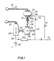
- FIG. 1 is a simplified schematic diagram of a pumping system constructed in accordance with the principles of this invention.
- FIG. 2 is a simplified schematic diagram of a rotary lobe pump showing the injection of cooling liquid in accordance with this invention.
- FIG. 3 is similar to FIG. 2 and shows a subsequent stage in the operating cycle of the rotary lobe pump.
- FIG. 4 is again similar to FIGS. 2 and 3 and shows a still later stage in the operating cycle of the rotary lobe pump.
- FIG. 1 An illustrative two-stage gas pumping system 10 constructed in accordance with this invention is shown in FIG. 1.
- Gas to be pumped enters the system via conduit 12, which conveys the gas to the inlet of rotary lobe pump 20.
- Pump 20 acts as a first stage or booster for liquid ring pump 40.
- FIGS. 2-4 The construction and operation of rotary lobe pump 20 is shown in more detail in FIGS. 2-4.
- An intake position of lobes 22 is shown in FIG. 2.
- a dwell position of lobes 22 is shown in FIG. 3.
- a compression and exhaust position of lobes 22 is shown in FIG. 4. Note that no compression of the gas occurs until after the dwell position shown in FIG. 3, i.e., until the compression stage illustrated by FIG. 4.
- liquid e.g., water
- rotary lobe pump 20 liquid is sprayed into the discharge of rotary lobe pump 20 from conduit 24 so that this liquid mixes intimately with the gas in the compression zone or internal compression chamber of pump 20.
- This prevents or at least substantially reduces heating of the gas being compressed.
- This prevents or substantially reduces heat transfer from the gas being compressed to the lobes 22 of pump 20.
- Lobes 22 therefore remain relatively cool, thereby greatly improving the performance and extending the operating range of pump 20.
- the cooling liquid spray may be arranged to at least partly traverse the compression zone of pump 20 and impinge on the surfaces of lobes 22 which define that compression zone. This arrangement of the cooling liquid spray is shown in FIGS. 2-4.
- Interstage conduit 30 conveys the partially compressed gas and expended cooling liquid from the discharge of first-stage rotary lobe pump 20 to the intake of second-stage liquid ring pump 40.
- Interstage conduit 30 may include a temperature switch 32 for monitoring the temperature of the gas in conduit 30 and for shutting down booster pump 20 or the entire system if the interstage gas temperature becomes too high (which may indicate that the cooling liquid injection via conduit 24 has failed).
- Interstage conduit 30 may also include a flexible connection 34 to allow for thermal expansion of the other conduit elements between pumps 20 and 40.
- a check valve 36 is also preferably included in interstage conduit 30 to prevent liquid from pump 40 from being sucked back into the apparatus upstream of conduit 12 when the system is shut down.
- Liquid ring pump 40 further compresses the gas received from interstage conduit 30 and discharges the fully compressed gas to separator 50 via conduit 42.
- the liquid used as the seal or pumping liquid in liquid ring pump 40 is preferably the same as (or at least compatible with) the liquid injected into the discharge of pump 20 via conduit 24. Accordingly, the cooling liquid injected via conduit 24 mixes with and thereby becomes part of the liquid ring pump pumping liquid when the cooling liquid enters the liquid ring pump.
- Separator 50 separates the liquid from the gas discharged by liquid ring pump 40.
- the gas is discharged from the system via conduit 52.
- the liquid could be discharged via conduit 54 and valve 56, but instead is preferably recycled by feeding it back to pump 40 and the discharge of pump 20 as will now be described.
- the loop for thus recycling the liquid from separator 50 preferably includes cooler 60 for cooling the liquid being recycled, e.g., by heat exchange with the atmosphere or a secondary liquid cooling circuit in which the secondary liquid flows countercurrent to the recycled liquid being cooled.
- a portion of the cooled liquid is then fed back into the liquid ring of pump 40 via conduit 62 (which may include valve 64 and fixed-orifice flow-control device 66).
- the other cooled liquid is injected into the discharge of pump 20 via conduit 24 as described above.
- Conduit 24 may include another fixed-orifice flow-control device 26.
- Any liquid losses or withdrawals are made up with fresh liquid from supply conduit 70.
- the make-up seal liquid for pump 40 and the liquid for injection into the discharge of pump 20 may all be supplied from conduit 70.
- the liquid for injection into the discharge of pump 20 may be fresh liquid from conduit 70 (supplied via valve 72 with valve 74 shut off).
- Various other combinations or mixtures of fresh and recirculated liquid may be used as liquid supplies for pumps 20 and 40, and the liquids supplied to the two pumps may be different if desired, as long as they are compatible.
- the suction pressure is to be 10.0 Torr (i.e., 10.0 mm Hg absolute (1 atmosphere equals approximately 760 Torr)), that the inlet temperature is 75°F, that the inlet gas is 30 lb/hr air (510 ACFM), that the discharge pressure of the rotary lobe booster pump is 75.0 Torr, that the booster discharge temperature is 952°F (based on 68% volumetric efficiency (“Ve”) and 0.6 temperature rise coefficient (“TRC”), that the injection water temperature is 85°F, and that the maximum desired booster pump discharge temperature is selected to be 250°F.
- the solution of the present invention is to inject a relatively large amount of liquid into the discharge of rotary lobe pump 20 and allow the resulting gas/vapor mixture to come to an acceptable equilibrium temperature.
- the presence of excess "liquid phase" injection water will prevent subcooling and freezing, while the relatively cool equilibrium temperatures minimize vapor loading to liquid ring pump 40.
- Equilibrium temperature 75.5°F (this value was derived after several iterations); Mass, water vapor to saturate at 75.5°F, 75.0 Torr, 30 lb/hr air: 8.0 lb/hr; Cooling available as a result of flashing water vapor: 8,784 BTU/hr; Heat load:
- the present invention has a number of important advantages.
- the invention makes greater compression ratios possible. (Currently, applications are limited by temperature rise.) This in turn reduces the number of booster stages required and/or the size of the required liquid ring pump.
- the invention is especially useful in systems designed to produce a subatmospheric gas pressure at the rotary lobe pump inlet, and wherein that subatmospheric gas pressure is approximately at or below the vapor pressure of the cooling liquid.
- Another advantage of the present invention is that it facilitates simultaneously starting both of pumps 20 and 40 from atmospheric pressure without fear of overheating booster pump 20, even during lengthy evacuation times.
- the systems of the present invention are exceptional rough vacuum evacuation devices.
- Yet another advantage of the invention is that the flow rate of the injection liquid does not have to be carefully controlled because of the unique ability of the liquid ring pump to accept wide variations in the liquid flow rate to its inlet with no adverse effect on its capacity or reliability.
- Still another advantage of the present invention is that the use of a liquid ring backing pump 40 eliminates the need for intercoolers or interstage separation devices.
- the injection liquid can serve as a portion of the liquid ring pump seal liquid.
- Yet another advantage of the invention is that the use of injection liquid prevents booster pump 20 overheating during upset or reduced flow conditions where the staging ratio may be extended beyond design.
Landscapes
- Engineering & Computer Science (AREA)
- Mechanical Engineering (AREA)
- General Engineering & Computer Science (AREA)
- Applications Or Details Of Rotary Compressors (AREA)
Applications Claiming Priority (2)
| Application Number | Priority Date | Filing Date | Title |
|---|---|---|---|
| US497326 | 1990-03-22 | ||
| US07/497,326 US5131817A (en) | 1990-03-22 | 1990-03-22 | Two-stage pumping system |
Publications (2)
| Publication Number | Publication Date |
|---|---|
| EP0447716A1 true EP0447716A1 (de) | 1991-09-25 |
| EP0447716B1 EP0447716B1 (de) | 1995-08-02 |
Family
ID=23976408
Family Applications (1)
| Application Number | Title | Priority Date | Filing Date |
|---|---|---|---|
| EP90313636A Expired - Lifetime EP0447716B1 (de) | 1990-03-22 | 1990-12-14 | Zweistufiges Pumpsystem |
Country Status (4)
| Country | Link |
|---|---|
| US (1) | US5131817A (de) |
| EP (1) | EP0447716B1 (de) |
| CA (1) | CA2034039C (de) |
| DE (1) | DE69021370T2 (de) |
Cited By (3)
| Publication number | Priority date | Publication date | Assignee | Title |
|---|---|---|---|---|
| US5244352A (en) * | 1988-06-24 | 1993-09-14 | Siemens Aktiengesellschaft | Multi-stage vacuum pump installation |
| GB2349426A (en) * | 1999-03-30 | 2000-11-01 | Aisin Seiki | A multi-stage pump assembly with flexible fluid connections between pumps |
| CN104632630A (zh) * | 2013-11-13 | 2015-05-20 | 中国科学院沈阳科学仪器股份有限公司 | 一种罗茨干泵热膨胀的控制系统及方法 |
Families Citing this family (9)
| Publication number | Priority date | Publication date | Assignee | Title |
|---|---|---|---|---|
| US5273412A (en) * | 1991-03-28 | 1993-12-28 | Grasso's Koninklijke Machinefabrieken N.V. | Lubricated rotary compressor having a cooling medium inlet to the delivery port |
| IT1289796B1 (it) * | 1996-12-23 | 1998-10-16 | Elasis Sistema Ricerca Fiat | Perfezionamenti ad un dispositivo a pompa per l'alimentazione del carburante da un serbatoio ad un motore a combustione interna. |
| US5899668A (en) * | 1997-01-30 | 1999-05-04 | The Nash Engineering Company | Two-stage liquid ring pumps having separate gas and liquid inlets to the second stage |
| US20110194950A1 (en) * | 2010-02-10 | 2011-08-11 | Shenoi Ramesh B | Efficiency improvements for liquid ring pumps |
| US11815095B2 (en) * | 2019-01-10 | 2023-11-14 | Elival Co., Ltd | Power saving vacuuming pump system based on complete-bearing-sealing and dry-large-pressure-difference root vacuuming root pumps |
| US20230167822A1 (en) * | 2021-09-27 | 2023-06-01 | Raymond Zhou Shaw | Vacuum system having condenser and root vacuum pump set |
| US12320353B2 (en) * | 2021-09-27 | 2025-06-03 | Elivac Co., Ltd | Vacuum system having condenser and root vacuum pump set |
| US20230096279A1 (en) * | 2021-09-27 | 2023-03-30 | Raymond Zhou Shaw | Vacuum system having condenser and root vacuum pump set |
| CN114837950B (zh) * | 2022-05-27 | 2024-06-21 | 山东省章丘鼓风机股份有限公司 | 罗茨真空泵的逆流口面积计算及位置确定的方法 |
Citations (3)
| Publication number | Priority date | Publication date | Assignee | Title |
|---|---|---|---|---|
| DE1428248A1 (de) * | 1962-12-01 | 1969-02-13 | Svenska Rotor Maskiner Ab | Drehkolben-Kompressormaschine |
| US3642384A (en) * | 1969-11-19 | 1972-02-15 | Henry Huse | Multistage vacuum pumping system |
| US4812110A (en) * | 1986-08-11 | 1989-03-14 | Kabushiki Kaisha Kobe Seiko Sho | Oil-free screw compressor with bypass of cooled discharged gas |
Family Cites Families (26)
| Publication number | Priority date | Publication date | Assignee | Title |
|---|---|---|---|---|
| US117626A (en) * | 1871-08-01 | Improvement in supplying water to air-pumps | ||
| US1097783A (en) * | 1911-01-28 | 1914-05-26 | Burgess Sulphite Fibre Co | Process of blowing acid gases. |
| US1155335A (en) * | 1912-12-30 | 1915-10-05 | Augustus Lea Bricknell | Internal-combustion engine. |
| US1340165A (en) * | 1919-05-26 | 1920-05-18 | Worthington Pump & Mach Corp | Condenser system and vacuum-pump |
| US1491993A (en) * | 1919-11-01 | 1924-04-29 | Delco Light Co | Rotary pressure or vacuum pump |
| US2404660A (en) * | 1943-08-26 | 1946-07-23 | Wilfred J Rouleau | Air compressor |
| US2489887A (en) * | 1946-07-11 | 1949-11-29 | Roots Connersville Blower Corp | Rotary pump |
| FR1129872A (fr) * | 1954-08-21 | 1957-01-28 | Heraeus Gmbh W C | Pompe mécanique à vide poussé du type roots |
| US2971691A (en) * | 1955-08-16 | 1961-02-14 | Heraeus Gmbh W C | Pumping system |
| GB810166A (en) * | 1957-01-30 | 1959-03-11 | Hathaway Ltd L | Improvements in and relating to priming systems for centrifugal pumps |
| SE317154B (de) * | 1959-01-15 | 1969-11-10 | Svenska Rotor Maskiner Ab | |
| US3105630A (en) * | 1960-06-02 | 1963-10-01 | Atlas Copco Ab | Compressor units |
| US3109297A (en) * | 1961-09-20 | 1963-11-05 | Gen Electric | Rotary compressor injection cooling arrangement |
| FR1381968A (fr) * | 1963-02-12 | 1964-12-14 | Dispositif pour l'aspiration des liquides, de l'air et des particules solides | |
| SE310751B (de) * | 1963-12-23 | 1969-05-12 | Svenska Rotor Maskiner Ab | |
| US3231179A (en) * | 1964-06-02 | 1966-01-25 | Technical Ind Inc | Lobular type of pump |
| GB1172993A (en) * | 1966-02-23 | 1969-12-03 | Plessey Co Ltd | Improvements in or relating to Rotary-Positive Displacement Machines |
| US3575539A (en) * | 1968-11-27 | 1971-04-20 | United States Steel Corp | Apparatus for suppressing vibration in a helical-rotor axial-flow compressor supplied with sealing water |
| FR2097285A5 (de) * | 1970-07-01 | 1972-03-03 | Joy Mfg Co | |
| US3910731A (en) * | 1970-07-09 | 1975-10-07 | Svenska Rotor Maskiner Ab | Screw rotor machine with multiple working spaces interconnected via communication channel in common end plate |
| US3922110A (en) * | 1974-01-28 | 1975-11-25 | Henry Huse | Multi-stage vacuum pump |
| US3956072A (en) * | 1975-08-21 | 1976-05-11 | Atlantic Fluidics, Inc. | Vapor distillation apparatus with two disparate compressors |
| US4123203A (en) * | 1977-10-14 | 1978-10-31 | Gardner-Denver Company | Multistage helical screw compressor with liquid injection |
| DE3209035A1 (de) * | 1981-03-13 | 1982-09-30 | Sullair Technology AB, 11653 Stockholm | Verfahren und vorrichtung zur zwischenkuehlung in einem oeleingespritzten mehrstufen-schraubenkompressor |
| JPS58183888A (ja) * | 1982-04-21 | 1983-10-27 | Hitachi Ltd | 油冷式スクリユ−圧縮機の給油装置 |
| JPH0733834B2 (ja) * | 1986-12-18 | 1995-04-12 | 株式会社宇野澤組鐵工所 | ロータ内蔵ハウジングの外周温度が安定化された内部分流逆流冷却多段式の三葉式真空ポンプ |
-
1990
- 1990-03-22 US US07/497,326 patent/US5131817A/en not_active Expired - Lifetime
- 1990-12-14 DE DE69021370T patent/DE69021370T2/de not_active Expired - Fee Related
- 1990-12-14 EP EP90313636A patent/EP0447716B1/de not_active Expired - Lifetime
-
1991
- 1991-01-11 CA CA002034039A patent/CA2034039C/en not_active Expired - Fee Related
Patent Citations (3)
| Publication number | Priority date | Publication date | Assignee | Title |
|---|---|---|---|---|
| DE1428248A1 (de) * | 1962-12-01 | 1969-02-13 | Svenska Rotor Maskiner Ab | Drehkolben-Kompressormaschine |
| US3642384A (en) * | 1969-11-19 | 1972-02-15 | Henry Huse | Multistage vacuum pumping system |
| US4812110A (en) * | 1986-08-11 | 1989-03-14 | Kabushiki Kaisha Kobe Seiko Sho | Oil-free screw compressor with bypass of cooled discharged gas |
Non-Patent Citations (1)
| Title |
|---|
| PATENT ABSTRACTS OF JAPAN vol. 8, no. 26 (M-273)(1463) 03 February 1984, & JP-A-58 183888 (HITACHI SEISAKUSHO K.K.) 27 October 1983, * |
Cited By (6)
| Publication number | Priority date | Publication date | Assignee | Title |
|---|---|---|---|---|
| US5244352A (en) * | 1988-06-24 | 1993-09-14 | Siemens Aktiengesellschaft | Multi-stage vacuum pump installation |
| GB2349426A (en) * | 1999-03-30 | 2000-11-01 | Aisin Seiki | A multi-stage pump assembly with flexible fluid connections between pumps |
| US6305910B1 (en) | 1999-03-30 | 2001-10-23 | Aisin Seiki Kabushiki Kaisha | Multi-stage pump device |
| GB2349426B (en) * | 1999-03-30 | 2003-08-27 | Aisin Seiki | A multi-stage pump assembly |
| CN104632630A (zh) * | 2013-11-13 | 2015-05-20 | 中国科学院沈阳科学仪器股份有限公司 | 一种罗茨干泵热膨胀的控制系统及方法 |
| CN104632630B (zh) * | 2013-11-13 | 2017-01-11 | 中国科学院沈阳科学仪器股份有限公司 | 一种罗茨干泵热膨胀的控制系统及方法 |
Also Published As
| Publication number | Publication date |
|---|---|
| EP0447716B1 (de) | 1995-08-02 |
| DE69021370D1 (de) | 1995-09-07 |
| CA2034039C (en) | 2000-10-24 |
| US5131817A (en) | 1992-07-21 |
| DE69021370T2 (de) | 1996-01-25 |
| CA2034039A1 (en) | 1991-09-23 |
Similar Documents
| Publication | Publication Date | Title |
|---|---|---|
| US5131817A (en) | Two-stage pumping system | |
| US6644931B2 (en) | System for pumping low thermal conductivity gases | |
| US4484457A (en) | Liquid-ring vacuum pump preceded by a precompressor | |
| US6446651B1 (en) | Multi-chamber vacuum system and a method of operating the same | |
| EP1008759A1 (de) | Gasverdichter | |
| JP2006292356A (ja) | 高性能熱ポンプ | |
| EP1199464B1 (de) | Vorrichtung zum Behandeln von in einem Tank enthaltenen Kraftstoffdämpfen mit Kraftstoffdampfsammelbehälter | |
| JP2000503108A (ja) | 液化天然ガスの保存・輸送方法および装置 | |
| US5511953A (en) | Mechanical compressor system | |
| US12486846B2 (en) | Gas compressor | |
| US4812110A (en) | Oil-free screw compressor with bypass of cooled discharged gas | |
| JP2007533844A (ja) | 真空設備用ゲートシステム | |
| US6071085A (en) | Gas ballast system for a multi-stage positive displacement pump | |
| CN109790836A (zh) | 无油压缩机及其运转方法 | |
| JP2733489B2 (ja) | ガス希釈をともなう逆流冷却式多段ロータリー形真空ポンプ | |
| JPH0746796Y2 (ja) | 再生ポンプ形圧縮機 | |
| CA2284698A1 (en) | Multi-stage jet pump arrangement for a vacuum apparatus | |
| RU96101605A (ru) | Способ подготовки газоконденсатной смеси к транспорту | |
| SE9802156L (sv) | Tvåstegskompressor och förfarande för kylning av densamma | |
| SE7500897L (de) | ||
| US20060147323A1 (en) | Device for supplying air to fuel cells | |
| JPS61159053A (ja) | ヒ−トポンプ | |
| JP3550616B2 (ja) | 冷凍設備に封入されている冷媒の回収方法、および、同回収装置 | |
| AU624358B2 (en) | A method and arrangement for pumping preferably refrigerants | |
| US4385868A (en) | Systems for evacuating process fluids having condensable and incondensable components |
Legal Events
| Date | Code | Title | Description |
|---|---|---|---|
| PUAI | Public reference made under article 153(3) epc to a published international application that has entered the european phase |
Free format text: ORIGINAL CODE: 0009012 |
|
| AK | Designated contracting states |
Kind code of ref document: A1 Designated state(s): DE GB SE |
|
| 17P | Request for examination filed |
Effective date: 19920310 |
|
| 17Q | First examination report despatched |
Effective date: 19921127 |
|
| RAP1 | Party data changed (applicant data changed or rights of an application transferred) |
Owner name: THE NASH ENGINEERING COMPANY |
|
| GRAA | (expected) grant |
Free format text: ORIGINAL CODE: 0009210 |
|
| AK | Designated contracting states |
Kind code of ref document: B1 Designated state(s): DE GB SE |
|
| REF | Corresponds to: |
Ref document number: 69021370 Country of ref document: DE Date of ref document: 19950907 |
|
| PLBE | No opposition filed within time limit |
Free format text: ORIGINAL CODE: 0009261 |
|
| STAA | Information on the status of an ep patent application or granted ep patent |
Free format text: STATUS: NO OPPOSITION FILED WITHIN TIME LIMIT |
|
| 26N | No opposition filed | ||
| PGFP | Annual fee paid to national office [announced via postgrant information from national office to epo] |
Ref country code: SE Payment date: 19981124 Year of fee payment: 9 |
|
| PG25 | Lapsed in a contracting state [announced via postgrant information from national office to epo] |
Ref country code: SE Free format text: LAPSE BECAUSE OF NON-PAYMENT OF DUE FEES Effective date: 19991215 |
|
| EUG | Se: european patent has lapsed |
Ref document number: 90313636.4 |
|
| REG | Reference to a national code |
Ref country code: GB Ref legal event code: IF02 |
|
| REG | Reference to a national code |
Ref country code: GB Ref legal event code: 732E |
|
| PGFP | Annual fee paid to national office [announced via postgrant information from national office to epo] |
Ref country code: GB Payment date: 20031118 Year of fee payment: 14 |
|
| PGFP | Annual fee paid to national office [announced via postgrant information from national office to epo] |
Ref country code: DE Payment date: 20031125 Year of fee payment: 14 |
|
| PG25 | Lapsed in a contracting state [announced via postgrant information from national office to epo] |
Ref country code: GB Free format text: LAPSE BECAUSE OF NON-PAYMENT OF DUE FEES Effective date: 20041214 |
|
| PG25 | Lapsed in a contracting state [announced via postgrant information from national office to epo] |
Ref country code: DE Free format text: LAPSE BECAUSE OF NON-PAYMENT OF DUE FEES Effective date: 20050701 |
|
| GBPC | Gb: european patent ceased through non-payment of renewal fee |
Effective date: 20041214 |