EP0447740A1 - Dispositif d'usinage en particulier pour des pièces entassées - Google Patents
Dispositif d'usinage en particulier pour des pièces entassées Download PDFInfo
- Publication number
- EP0447740A1 EP0447740A1 EP90890044A EP90890044A EP0447740A1 EP 0447740 A1 EP0447740 A1 EP 0447740A1 EP 90890044 A EP90890044 A EP 90890044A EP 90890044 A EP90890044 A EP 90890044A EP 0447740 A1 EP0447740 A1 EP 0447740A1
- Authority
- EP
- European Patent Office
- Prior art keywords
- hold
- workpieces
- finger
- support surface
- unit
- Prior art date
- Legal status (The legal status is an assumption and is not a legal conclusion. Google has not performed a legal analysis and makes no representation as to the accuracy of the status listed.)
- Granted
Links
- 238000003754 machining Methods 0.000 title abstract description 15
- 238000005520 cutting process Methods 0.000 claims description 12
- 239000000463 material Substances 0.000 description 7
- 230000009471 action Effects 0.000 description 2
- 210000000078 claw Anatomy 0.000 description 2
- 238000005553 drilling Methods 0.000 description 2
- 239000000853 adhesive Substances 0.000 description 1
- 230000001070 adhesive effect Effects 0.000 description 1
- 239000002313 adhesive film Substances 0.000 description 1
- 229910052782 aluminium Inorganic materials 0.000 description 1
- XAGFODPZIPBFFR-UHFFFAOYSA-N aluminium Chemical compound [Al] XAGFODPZIPBFFR-UHFFFAOYSA-N 0.000 description 1
- 230000008859 change Effects 0.000 description 1
- 230000007812 deficiency Effects 0.000 description 1
- 238000010586 diagram Methods 0.000 description 1
- 239000010432 diamond Substances 0.000 description 1
- 238000006073 displacement reaction Methods 0.000 description 1
- 230000000694 effects Effects 0.000 description 1
- 230000002349 favourable effect Effects 0.000 description 1
- 230000008014 freezing Effects 0.000 description 1
- 238000007710 freezing Methods 0.000 description 1
- 230000003993 interaction Effects 0.000 description 1
- 229910052751 metal Inorganic materials 0.000 description 1
- 239000002184 metal Substances 0.000 description 1
- 238000000034 method Methods 0.000 description 1
- 238000003801 milling Methods 0.000 description 1
- 230000004048 modification Effects 0.000 description 1
- 238000012986 modification Methods 0.000 description 1
- 230000008569 process Effects 0.000 description 1
Images

Classifications
-
- B—PERFORMING OPERATIONS; TRANSPORTING
- B23—MACHINE TOOLS; METAL-WORKING NOT OTHERWISE PROVIDED FOR
- B23Q—DETAILS, COMPONENTS, OR ACCESSORIES FOR MACHINE TOOLS, e.g. ARRANGEMENTS FOR COPYING OR CONTROLLING; MACHINE TOOLS IN GENERAL CHARACTERISED BY THE CONSTRUCTION OF PARTICULAR DETAILS OR COMPONENTS; COMBINATIONS OR ASSOCIATIONS OF METAL-WORKING MACHINES, NOT DIRECTED TO A PARTICULAR RESULT
- B23Q3/00—Devices holding, supporting, or positioning work or tools, of a kind normally removable from the machine
- B23Q3/02—Devices holding, supporting, or positioning work or tools, of a kind normally removable from the machine for mounting on a work-table, tool-slide, or analogous part
- B23Q3/06—Work-clamping means
- B23Q3/069—Work-clamping means for pressing workpieces against a work-table
-
- Y—GENERAL TAGGING OF NEW TECHNOLOGICAL DEVELOPMENTS; GENERAL TAGGING OF CROSS-SECTIONAL TECHNOLOGIES SPANNING OVER SEVERAL SECTIONS OF THE IPC; TECHNICAL SUBJECTS COVERED BY FORMER USPC CROSS-REFERENCE ART COLLECTIONS [XRACs] AND DIGESTS
- Y10—TECHNICAL SUBJECTS COVERED BY FORMER USPC
- Y10T—TECHNICAL SUBJECTS COVERED BY FORMER US CLASSIFICATION
- Y10T409/00—Gear cutting, milling, or planing
- Y10T409/30—Milling
- Y10T409/30084—Milling with regulation of operation by templet, card, or other replaceable information supply
- Y10T409/300896—Milling with regulation of operation by templet, card, or other replaceable information supply with sensing of numerical information and regulation without mechanical connection between sensing means and regulated means [i.e., numerical control]
-
- Y—GENERAL TAGGING OF NEW TECHNOLOGICAL DEVELOPMENTS; GENERAL TAGGING OF CROSS-SECTIONAL TECHNOLOGIES SPANNING OVER SEVERAL SECTIONS OF THE IPC; TECHNICAL SUBJECTS COVERED BY FORMER USPC CROSS-REFERENCE ART COLLECTIONS [XRACs] AND DIGESTS
- Y10—TECHNICAL SUBJECTS COVERED BY FORMER USPC
- Y10T—TECHNICAL SUBJECTS COVERED BY FORMER US CLASSIFICATION
- Y10T83/00—Cutting
- Y10T83/162—With control means responsive to replaceable or selectable information program
- Y10T83/173—Arithmetically determined program
- Y10T83/18—With operator input means
-
- Y—GENERAL TAGGING OF NEW TECHNOLOGICAL DEVELOPMENTS; GENERAL TAGGING OF CROSS-SECTIONAL TECHNOLOGIES SPANNING OVER SEVERAL SECTIONS OF THE IPC; TECHNICAL SUBJECTS COVERED BY FORMER USPC CROSS-REFERENCE ART COLLECTIONS [XRACs] AND DIGESTS
- Y10—TECHNICAL SUBJECTS COVERED BY FORMER USPC
- Y10T—TECHNICAL SUBJECTS COVERED BY FORMER US CLASSIFICATION
- Y10T83/00—Cutting
- Y10T83/748—With work immobilizer
- Y10T83/7487—Means to clamp work
- Y10T83/758—With means to adjust clamp position or stroke
Definitions
- the invention relates to a device for machining, in particular, superimposed workpieces, with a mounting table having a support surface and a clamping device and a numerically controlled tool unit that can be moved over the support surface.
- the workpiece stack In order to be able to machine workpieces stacked on top of one another in several layers, for example cutting and drilling workpiece parts from sheet metal plates or film-covered prepreg materials or the like. To be able to cut non-adhesive materials, the workpiece stack must be appropriately held, on the one hand with respect to the support surface and on the other hand with respect to the individual layers themselves. For this purpose, the workpieces have previously been screwed or riveted in stacks with a lower lost clamping pallet and the clamping pallet is then about the clamping device, the hold-down claws, suction boxes for the support surface and the like. may have held on to the table.
- the invention is therefore based on the object of eliminating these deficiencies and of creating a device of the type described at the outset which, in a relatively simple manner, permits rational clamping of any workpiece stack and can be used in a wide range in a wide variety of different machining operations.
- the clamping device comprises at least one hold-down unit comprising a hold-down slide that can be moved over the support surface and a position-adjustable and force-holdable hold-down finger and that the slide drives and finger actuators can be controlled depending on the control of the tool unit.
- This hold-down unit allows the hold-down finger to be freely positioned, and its interaction with the control of the tool assembly enables the use of this hold-down unit or hold-down finger to be temporally and spatially coordinated with the machining process to be carried out by the tool assembly.
- the workpiece layers can thus always be pressed together in a region that is favorable for the machining process, so that there is no fear of mutual relative displacement of the layers due to the machining forces.
- the hold-down unit that can be used for a wide variety of workpieces and work is sufficient. If several workpieces are cut out of a material stack or the workpieces are cut into different parts disassembled, it will be expedient, or the like, the material stack as a whole on the support surface by conventional clamping claws. or in vacuum tables to be fixed to the support surface by suction, for which purpose the stack advantageously comes on a clamping pallet, which, however, only serves as a base and can therefore be reused as often as desired.
- This clamping pallet brings with it the hold in relation to the support surface and the hold-down unit then ensures the holding of the material layers or the workpiece parts worked out from the layers and the like. opposite the pallet.
- the hold-down finger carries a brakable hold-down roller
- the hold-down roller rolls on the uppermost workpiece with constant hold-down pressure, but it is braked in the desired hold-down position to prevent relative movement between the hold-down finger and the stack of workpieces.
- the hold-down slide accommodates two hold-down fingers that can be actuated individually, so that these hold-down fingers can be used simultaneously or alternately.
- two hold-down fingers can be used, then as soon as the tool has left the area of the second hold-down finger, the second hold-down finger and before the tool returns to the starting point, lift off the first hold-down finger, in order to be able to carry out the closed machining process without interrupting the tool insert and without interrupting the hold-down action.
- the two hold-down fingers can also be used to fix workpieces after a machining-related division into two, or even to double the hold-down forces of one finger.
- one of the hold-down fingers can be positioned on the workpieces in such a way that the cutting force resultant in the end area of the closing cutting process passes through the attachment area of the hold-down finger, a torque load on the stack caused by cutting force is avoided or at least kept within narrow limits, so that with relatively low hold-down forces the desired fixation of the workpieces is guaranteed.
- the hold-down unit is an independent device assigned to the clamping table, it is possible to use the hold-down unit for other purposes as well.
- the hold-down device can accommodate a tool changing device for the tool unit, thereby simplifying the tool changing process of the tool unit.
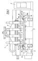
- a device 1 For the joint processing of layers placed in several layers Workpieces W there is a device 1 with a clamping table 2 and a tool unit 3.
- the clamping table 2 forms a support surface 4 for placing the workpieces to be machined and a clamping device, for example a vacuum pump 5 for pressurizing the work surface 4, for holding the workpieces on the Contact surface.
- the tool assembly 3 is equipped with one or more tools 6, such as drilling or milling tools, which can be moved over the bearing surface 4. It is only a question of the relative movement between tools or tool assembly and the support surface, so that the support surface and / or tool assembly could be moved to position the tools.
- a numerical control 7 ensures the desired positioning of the tools 6 and the machining process.
- the clamping device comprises, in addition to the vacuum device for the support surface 4, one or more hold-down units 8, 9, depending on the requirements, each consisting of a hold-down slide 10 that can be moved over the support surface and at least there is a position-adjustable and force-acting hold-down finger 11, 12.
- the hold-down slide 10 is composed of a longitudinal slide 10a and a cross slide 10b, so that the hold-down fingers 11, 12 can be positioned as desired in the area of the support surface 4 and also the slide drives 13, 14 and the actuators 15, 16 for the hold-down fingers are via the Numerical control 7 can be controlled depending on the work program of the tool assembly 3. This means that the hold-down fingers can be used in the cheapest workpiece area and the hold-down effect can also be optimally adapted to the machining process.
- two individually operable hold-down fingers 11 can be provided, or it is also possible, as with the hold-down unit 9, to provide only one hold-down finger 12, which then carries a hold-down roller 17 with a brake 18. So on the one hand the pair of hold-downs 11 can be used alternately and overlapping or on the other hand the hold-down action can be maintained by the hold-down roller 17 even during a change in position, the hold-down position of this hold-down finger 12 being fixable by braking the hold-down roller.
- the hold-down unit 9 with its hold-down roller 17 can at least gradually follow a closed cutting process without reducing the hold-down force, so that a circumferential cut is possible without hindrance by the hold-down fingers.
- the hold-down unit 8 as shown in FIG.
- the hold-down fingers 11 are used alternately, the first finger 11 a first being pushed in and put on, then the tool begins its cut at point A and cuts the cut course S accordingly until the attachment area of the second hold-down finger 11b is exceeded, for example at point B, whereupon the second hold-down finger 11b extends and is placed on the workpiece part T and the first hold-down finger 11a can be released and retracted, as a result of which the entire cutting curve S is now free for machining.
- the first hold-down finger 11a can hold down the remaining workpiece rest in the retracted position, so that a perfect fixation of the stack is ensured.
- the workpiece stack with the interposition of an appropriate clamping pallet or a suitable base made of film or paper on the support surface by applying negative pressure, so that an excellent clamping of the workpieces is guaranteed even with multi-layer stacks.
Landscapes
- Engineering & Computer Science (AREA)
- Mechanical Engineering (AREA)
- Jigs For Machine Tools (AREA)
- Manufacture, Treatment Of Glass Fibers (AREA)
- Bending Of Plates, Rods, And Pipes (AREA)
- Electrical Discharge Machining, Electrochemical Machining, And Combined Machining (AREA)
Priority Applications (5)
| Application Number | Priority Date | Filing Date | Title |
|---|---|---|---|
| ES90890044T ES2052238T3 (es) | 1990-02-21 | 1990-02-21 | Dispositivo para mecanizar especialmente piezas de trabajo puestas unas sobre otras. |
| EP90890044A EP0447740B1 (fr) | 1990-02-21 | 1990-02-21 | Dispositif d'usinage en particulier pour des pièces entassées |
| AT9090890044T ATE104889T1 (de) | 1990-02-21 | 1990-02-21 | Vorrichtung zum bearbeiten von insbesondere uebereinandergelegten werkstuecken. |
| DE59005538T DE59005538D1 (de) | 1990-02-21 | 1990-02-21 | Vorrichtung zum Bearbeiten von insbesondere übereinandergelegten Werkstücken. |
| US07/657,328 US5137399A (en) | 1990-02-21 | 1991-02-19 | Apparatus for processing workpieces |
Applications Claiming Priority (1)
| Application Number | Priority Date | Filing Date | Title |
|---|---|---|---|
| EP90890044A EP0447740B1 (fr) | 1990-02-21 | 1990-02-21 | Dispositif d'usinage en particulier pour des pièces entassées |
Publications (2)
| Publication Number | Publication Date |
|---|---|
| EP0447740A1 true EP0447740A1 (fr) | 1991-09-25 |
| EP0447740B1 EP0447740B1 (fr) | 1994-04-27 |
Family
ID=8206101
Family Applications (1)
| Application Number | Title | Priority Date | Filing Date |
|---|---|---|---|
| EP90890044A Expired - Lifetime EP0447740B1 (fr) | 1990-02-21 | 1990-02-21 | Dispositif d'usinage en particulier pour des pièces entassées |
Country Status (5)
| Country | Link |
|---|---|
| US (1) | US5137399A (fr) |
| EP (1) | EP0447740B1 (fr) |
| AT (1) | ATE104889T1 (fr) |
| DE (1) | DE59005538D1 (fr) |
| ES (1) | ES2052238T3 (fr) |
Cited By (3)
| Publication number | Priority date | Publication date | Assignee | Title |
|---|---|---|---|---|
| CN102229057A (zh) * | 2011-06-20 | 2011-11-02 | 无锡科博增压器有限公司 | 加工中心辅助夹具 |
| CN108857895A (zh) * | 2018-08-09 | 2018-11-23 | 中铁上海工程局集团有限公司 | 可调式校直钢轨夹持装置及其使用方法 |
| CN112917194A (zh) * | 2020-12-28 | 2021-06-08 | 安徽展新电子有限公司 | 一种铝基板裁切的固定机构 |
Families Citing this family (6)
| Publication number | Priority date | Publication date | Assignee | Title |
|---|---|---|---|---|
| US5826866A (en) * | 1997-02-03 | 1998-10-27 | Ernst Thielenhaus Kg | System for holding a thin-walled workpiece during machining |
| WO1999011438A1 (fr) * | 1997-09-02 | 1999-03-11 | The Challenge Machinery Company | Systeme a pression de serrage programmable |
| IT1298389B1 (it) * | 1997-12-24 | 2000-01-05 | Giben Impianti Spa | Macchina sezionatrice per il taglio di pannelli e relativo metodo di taglio. |
| US6178860B1 (en) * | 1998-09-10 | 2001-01-30 | The Fletcher-Terry Company | Matcutter with clamping system and cutting head |
| IT1320611B1 (it) * | 2000-08-30 | 2003-12-10 | Pluritec Italia | Sistema premipezzo per una macchina foratrice, in particolare perschede di circuiti stampati. |
| DE102012207867B3 (de) * | 2012-05-11 | 2013-06-13 | Trumpf Werkzeugmaschinen Gmbh + Co. Kg | Verfahren und Vorrichtung zum Abführen eines an einer Werkzeugmaschine anfallenden Werkstückrestes |
Citations (5)
| Publication number | Priority date | Publication date | Assignee | Title |
|---|---|---|---|---|
| DE390872C (de) * | 1922-08-09 | 1924-03-01 | Obira Oval Und Bilderrahmenfab | Vorrichtung zum Bearbeiten ovaler Gegenstaende |
| US3587391A (en) * | 1969-09-25 | 1971-06-28 | Robert D Pitts | Work support mechanism |
| EP0010043A1 (fr) * | 1978-10-06 | 1980-04-16 | Jean Vierstraete | Dispositif tournant de compression de pièces plates fixé sur un des éléments d'usinage d'une machine-outils |
| EP0019292A1 (fr) * | 1979-05-22 | 1980-11-26 | GIBEN IMPIANTI S.p.A. | Machines à scier |
| US4819532A (en) * | 1985-05-10 | 1989-04-11 | Benuzzi Gino | Sawing machine |
Family Cites Families (4)
| Publication number | Priority date | Publication date | Assignee | Title |
|---|---|---|---|---|
| US3700227A (en) * | 1970-12-09 | 1972-10-24 | Applied Power Ind Inc | Traversing workholding clamp |
| BE792406A (fr) * | 1971-12-07 | 1973-03-30 | Bystronic Masch | Dispositif a plusieurs outils pour le travail simultane d'une matiere deplacee par rapport aux outils, notamment pour decouper une plaque de verre |
| US3805650A (en) * | 1973-03-26 | 1974-04-23 | Gerber Garment Technology Inc | Apparatus and method for cutting sheet material |
| CH643478A5 (de) * | 1980-04-14 | 1984-06-15 | Erwin Jenkner | Besaeumeinrichtung fuer plattenfoermige werkstuecke mit ueberstehenden deckschichten. |
-
1990
- 1990-02-21 ES ES90890044T patent/ES2052238T3/es not_active Expired - Lifetime
- 1990-02-21 AT AT9090890044T patent/ATE104889T1/de active
- 1990-02-21 EP EP90890044A patent/EP0447740B1/fr not_active Expired - Lifetime
- 1990-02-21 DE DE59005538T patent/DE59005538D1/de not_active Expired - Fee Related
-
1991
- 1991-02-19 US US07/657,328 patent/US5137399A/en not_active Expired - Fee Related
Patent Citations (5)
| Publication number | Priority date | Publication date | Assignee | Title |
|---|---|---|---|---|
| DE390872C (de) * | 1922-08-09 | 1924-03-01 | Obira Oval Und Bilderrahmenfab | Vorrichtung zum Bearbeiten ovaler Gegenstaende |
| US3587391A (en) * | 1969-09-25 | 1971-06-28 | Robert D Pitts | Work support mechanism |
| EP0010043A1 (fr) * | 1978-10-06 | 1980-04-16 | Jean Vierstraete | Dispositif tournant de compression de pièces plates fixé sur un des éléments d'usinage d'une machine-outils |
| EP0019292A1 (fr) * | 1979-05-22 | 1980-11-26 | GIBEN IMPIANTI S.p.A. | Machines à scier |
| US4819532A (en) * | 1985-05-10 | 1989-04-11 | Benuzzi Gino | Sawing machine |
Cited By (4)
| Publication number | Priority date | Publication date | Assignee | Title |
|---|---|---|---|---|
| CN102229057A (zh) * | 2011-06-20 | 2011-11-02 | 无锡科博增压器有限公司 | 加工中心辅助夹具 |
| CN108857895A (zh) * | 2018-08-09 | 2018-11-23 | 中铁上海工程局集团有限公司 | 可调式校直钢轨夹持装置及其使用方法 |
| CN108857895B (zh) * | 2018-08-09 | 2023-05-12 | 中铁上海工程局集团有限公司 | 可调式校直钢轨夹持装置及其使用方法 |
| CN112917194A (zh) * | 2020-12-28 | 2021-06-08 | 安徽展新电子有限公司 | 一种铝基板裁切的固定机构 |
Also Published As
| Publication number | Publication date |
|---|---|
| ATE104889T1 (de) | 1994-05-15 |
| EP0447740B1 (fr) | 1994-04-27 |
| US5137399A (en) | 1992-08-11 |
| ES2052238T3 (es) | 1994-07-01 |
| DE59005538D1 (de) | 1994-06-01 |
Similar Documents
| Publication | Publication Date | Title |
|---|---|---|
| DE4140768C2 (de) | Offset-Druckform | |
| DE3333267A1 (de) | Spanabhebende maschine mit eier materialsaugeinrichtung | |
| EP0509188B1 (fr) | Machine-outil à usiner des plaques | |
| EP0447740B1 (fr) | Dispositif d'usinage en particulier pour des pièces entassées | |
| DE102009015919A1 (de) | Vorrichtung und Verfahren zur Herstellung zumindest eines Werkstücks | |
| DE102016118175B4 (de) | Werkzeugmaschine und Verfahren zum Bearbeiten von plattenförmigen Werkstücken | |
| EP0505668A1 (fr) | Table de travail à vide | |
| DE19858791B4 (de) | Plattenbearbeitungsmaschine | |
| DE3918120C2 (fr) | ||
| DE7913260U1 (de) | Stanzpresse | |
| CH655041A5 (de) | Schneidpresse zur bearbeitung plattenfoermiger bauteile. | |
| DE102015107470A1 (de) | Verfahren und Vorrichtung zum Abführen eines Werkstücks mit einem unebenen oder konturierten Flächenabschnitt aus einer Bearbeitungsmaschine | |
| DE1242999B (de) | Vorrichtung zum rotierenden Stanzen von flexiblen Bahnen wie Papier, schwacher Karton, Folien od. dgl. | |
| DE2127525C3 (de) | Zusatzeinrichtung für Drehautomaten zum spanlosen Ablängen von in der umlaufenden Werkstückspindel eingespannten Rohren oder dgl | |
| EP2502716B1 (fr) | Outil pour une machine de traitement de tôle et procédé de séparation d'une feuille | |
| DE102005002595B4 (de) | Greifeinrichtung, insbesondere Spannzange, zur Verwendung bei einer Vorschubvorrichtung für plattenförmige Werkstücke | |
| EP0394521B1 (fr) | Procédé et dispositif pour le découpage ou le délignage de pièces de bois ou similaires | |
| DE3930463C2 (fr) | ||
| DE547190C (de) | Verfahren und Vorrichtung zur Herstellung gelochter oder ausgeschnittener Werkstuecke durch Stanzen aus plattenfoermigem Material | |
| EP4364917B1 (fr) | Dispositif de traitement du bois et procédé d'usinage de pièces en forme de plaque | |
| DE2602921A1 (de) | Verfahren zum trennen von moebelbauplatten sowie einrichtung zur durchfuehrung dieses verfahrens | |
| DE9211268U1 (de) | Universalspannplatte | |
| EP1741517B1 (fr) | Dispositif de fixation à dépression pour une pièce plate et méthode de fabrication de la pièce plate | |
| DE9012791U1 (de) | Vorrichtung zum Positionieren von Werkstücken bei der spanabhebenden Verformung | |
| EP1175271A1 (fr) | Procede de traitement par striation de pieces usinees en forme de plaques et dispositif approprie |
Legal Events
| Date | Code | Title | Description |
|---|---|---|---|
| PUAI | Public reference made under article 153(3) epc to a published international application that has entered the european phase |
Free format text: ORIGINAL CODE: 0009012 |
|
| AK | Designated contracting states |
Kind code of ref document: A1 Designated state(s): AT DE ES FR GB IT |
|
| 17P | Request for examination filed |
Effective date: 19920114 |
|
| 17Q | First examination report despatched |
Effective date: 19930222 |
|
| GRAA | (expected) grant |
Free format text: ORIGINAL CODE: 0009210 |
|
| AK | Designated contracting states |
Kind code of ref document: B1 Designated state(s): AT DE ES FR GB IT |
|
| REF | Corresponds to: |
Ref document number: 104889 Country of ref document: AT Date of ref document: 19940515 Kind code of ref document: T |
|
| REF | Corresponds to: |
Ref document number: 59005538 Country of ref document: DE Date of ref document: 19940601 |
|
| REG | Reference to a national code |
Ref country code: ES Ref legal event code: FG2A Ref document number: 2052238 Country of ref document: ES Kind code of ref document: T3 |
|
| ET | Fr: translation filed | ||
| GBT | Gb: translation of ep patent filed (gb section 77(6)(a)/1977) |
Effective date: 19940615 |
|
| ITF | It: translation for a ep patent filed | ||
| PGFP | Annual fee paid to national office [announced via postgrant information from national office to epo] |
Ref country code: GB Payment date: 19950208 Year of fee payment: 6 |
|
| PGFP | Annual fee paid to national office [announced via postgrant information from national office to epo] |
Ref country code: ES Payment date: 19950220 Year of fee payment: 6 |
|
| PGFP | Annual fee paid to national office [announced via postgrant information from national office to epo] |
Ref country code: FR Payment date: 19950221 Year of fee payment: 6 |
|
| PGFP | Annual fee paid to national office [announced via postgrant information from national office to epo] |
Ref country code: AT Payment date: 19950228 Year of fee payment: 6 |
|
| PLBE | No opposition filed within time limit |
Free format text: ORIGINAL CODE: 0009261 |
|
| STAA | Information on the status of an ep patent application or granted ep patent |
Free format text: STATUS: NO OPPOSITION FILED WITHIN TIME LIMIT |
|
| PGFP | Annual fee paid to national office [announced via postgrant information from national office to epo] |
Ref country code: DE Payment date: 19950303 Year of fee payment: 6 |
|
| 26N | No opposition filed | ||
| PG25 | Lapsed in a contracting state [announced via postgrant information from national office to epo] |
Ref country code: GB Effective date: 19960221 Ref country code: AT Effective date: 19960221 |
|
| PG25 | Lapsed in a contracting state [announced via postgrant information from national office to epo] |
Ref country code: ES Free format text: LAPSE BECAUSE OF NON-PAYMENT OF DUE FEES Effective date: 19960222 |
|
| GBPC | Gb: european patent ceased through non-payment of renewal fee |
Effective date: 19960221 |
|
| PG25 | Lapsed in a contracting state [announced via postgrant information from national office to epo] |
Ref country code: FR Effective date: 19961031 |
|
| PG25 | Lapsed in a contracting state [announced via postgrant information from national office to epo] |
Ref country code: DE Effective date: 19961101 |
|
| REG | Reference to a national code |
Ref country code: FR Ref legal event code: ST |
|
| REG | Reference to a national code |
Ref country code: ES Ref legal event code: FD2A Effective date: 19990405 |
|
| PG25 | Lapsed in a contracting state [announced via postgrant information from national office to epo] |
Ref country code: IT Free format text: LAPSE BECAUSE OF NON-PAYMENT OF DUE FEES;WARNING: LAPSES OF ITALIAN PATENTS WITH EFFECTIVE DATE BEFORE 2007 MAY HAVE OCCURRED AT ANY TIME BEFORE 2007. THE CORRECT EFFECTIVE DATE MAY BE DIFFERENT FROM THE ONE RECORDED. Effective date: 20050221 |