EP0447747B1 - Apparatus and method for injecting compounds in plasma for ICP-OES analysis - Google Patents
Apparatus and method for injecting compounds in plasma for ICP-OES analysis Download PDFInfo
- Publication number
- EP0447747B1 EP0447747B1 EP91100362A EP91100362A EP0447747B1 EP 0447747 B1 EP0447747 B1 EP 0447747B1 EP 91100362 A EP91100362 A EP 91100362A EP 91100362 A EP91100362 A EP 91100362A EP 0447747 B1 EP0447747 B1 EP 0447747B1
- Authority
- EP
- European Patent Office
- Prior art keywords
- argon
- plasma
- stream
- sample
- liquid
- Prior art date
- Legal status (The legal status is an assumption and is not a legal conclusion. Google has not performed a legal analysis and makes no representation as to the accuracy of the status listed.)
- Expired - Lifetime
Links
- 150000001875 compounds Chemical class 0.000 title claims description 23
- 238000004458 analytical method Methods 0.000 title claims description 15
- 238000000034 method Methods 0.000 title claims description 14
- 238000002354 inductively-coupled plasma atomic emission spectroscopy Methods 0.000 title 1
- XKRFYHLGVUSROY-UHFFFAOYSA-N Argon Chemical compound [Ar] XKRFYHLGVUSROY-UHFFFAOYSA-N 0.000 claims abstract description 138
- 229910052786 argon Inorganic materials 0.000 claims abstract description 69
- 239000007788 liquid Substances 0.000 claims abstract description 36
- 229910052751 metal Inorganic materials 0.000 claims abstract description 26
- 239000002184 metal Substances 0.000 claims abstract description 26
- 239000012535 impurity Substances 0.000 claims abstract description 17
- 150000002902 organometallic compounds Chemical class 0.000 claims abstract description 4
- 238000001636 atomic emission spectroscopy Methods 0.000 claims abstract description 3
- 238000010438 heat treatment Methods 0.000 claims description 40
- XCZXGTMEAKBVPV-UHFFFAOYSA-N trimethylgallium Chemical compound C[Ga](C)C XCZXGTMEAKBVPV-UHFFFAOYSA-N 0.000 claims description 16
- 238000002347 injection Methods 0.000 claims description 14
- 239000007924 injection Substances 0.000 claims description 14
- JLTRXTDYQLMHGR-UHFFFAOYSA-N trimethylaluminium Chemical compound C[Al](C)C JLTRXTDYQLMHGR-UHFFFAOYSA-N 0.000 claims description 9
- 125000002524 organometallic group Chemical group 0.000 claims description 5
- 239000000203 mixture Substances 0.000 claims description 4
- 230000003287 optical effect Effects 0.000 claims description 3
- 230000008016 vaporization Effects 0.000 claims description 3
- 238000009833 condensation Methods 0.000 claims description 2
- 230000005494 condensation Effects 0.000 claims description 2
- 238000001514 detection method Methods 0.000 abstract description 9
- 238000005259 measurement Methods 0.000 abstract description 5
- 230000005855 radiation Effects 0.000 abstract description 3
- 239000000523 sample Substances 0.000 description 61
- 239000007789 gas Substances 0.000 description 13
- 239000000047 product Substances 0.000 description 6
- 239000012086 standard solution Substances 0.000 description 6
- 229910052710 silicon Inorganic materials 0.000 description 5
- 229910052732 germanium Inorganic materials 0.000 description 4
- 150000002739 metals Chemical class 0.000 description 4
- 238000012360 testing method Methods 0.000 description 4
- 229910052718 tin Inorganic materials 0.000 description 4
- 238000004519 manufacturing process Methods 0.000 description 3
- 230000001105 regulatory effect Effects 0.000 description 3
- 239000010703 silicon Substances 0.000 description 3
- GYHNNYVSQQEPJS-UHFFFAOYSA-N Gallium Chemical compound [Ga] GYHNNYVSQQEPJS-UHFFFAOYSA-N 0.000 description 2
- XUIMIQQOPSSXEZ-UHFFFAOYSA-N Silicon Chemical compound [Si] XUIMIQQOPSSXEZ-UHFFFAOYSA-N 0.000 description 2
- ATJFFYVFTNAWJD-UHFFFAOYSA-N Tin Chemical compound [Sn] ATJFFYVFTNAWJD-UHFFFAOYSA-N 0.000 description 2
- 239000007864 aqueous solution Substances 0.000 description 2
- VQNPSCRXHSIJTH-UHFFFAOYSA-N cadmium(2+);carbanide Chemical compound [CH3-].[CH3-].[Cd+2] VQNPSCRXHSIJTH-UHFFFAOYSA-N 0.000 description 2
- 238000011088 calibration curve Methods 0.000 description 2
- 239000012159 carrier gas Substances 0.000 description 2
- LJSQFQKUNVCTIA-UHFFFAOYSA-N diethyl sulfide Chemical compound CCSCC LJSQFQKUNVCTIA-UHFFFAOYSA-N 0.000 description 2
- RVIXKDRPFPUUOO-UHFFFAOYSA-N dimethylselenide Chemical compound C[Se]C RVIXKDRPFPUUOO-UHFFFAOYSA-N 0.000 description 2
- 229910052733 gallium Inorganic materials 0.000 description 2
- GNPVGFCGXDBREM-UHFFFAOYSA-N germanium atom Chemical compound [Ge] GNPVGFCGXDBREM-UHFFFAOYSA-N 0.000 description 2
- 239000011521 glass Substances 0.000 description 2
- 239000000463 material Substances 0.000 description 2
- 239000006199 nebulizer Substances 0.000 description 2
- 239000012488 sample solution Substances 0.000 description 2
- 238000005070 sampling Methods 0.000 description 2
- 239000000243 solution Substances 0.000 description 2
- VCZQFJFZMMALHB-UHFFFAOYSA-N tetraethylsilane Chemical compound CC[Si](CC)(CC)CC VCZQFJFZMMALHB-UHFFFAOYSA-N 0.000 description 2
- ZRLCXMPFXYVHGS-UHFFFAOYSA-N tetramethylgermane Chemical compound C[Ge](C)(C)C ZRLCXMPFXYVHGS-UHFFFAOYSA-N 0.000 description 2
- VXKWYPOMXBVZSJ-UHFFFAOYSA-N tetramethyltin Chemical compound C[Sn](C)(C)C VXKWYPOMXBVZSJ-UHFFFAOYSA-N 0.000 description 2
- 229910021654 trace metal Inorganic materials 0.000 description 2
- XLYOFNOQVPJJNP-UHFFFAOYSA-N water Substances O XLYOFNOQVPJJNP-UHFFFAOYSA-N 0.000 description 2
- NYOZTOCADHXMEV-UHFFFAOYSA-N 2-propan-2-yltellanylpropane Chemical compound CC(C)[Te]C(C)C NYOZTOCADHXMEV-UHFFFAOYSA-N 0.000 description 1
- 101100293261 Mus musculus Naa15 gene Proteins 0.000 description 1
- OAICVXFJPJFONN-UHFFFAOYSA-N Phosphorus Chemical compound [P] OAICVXFJPJFONN-UHFFFAOYSA-N 0.000 description 1
- 238000010521 absorption reaction Methods 0.000 description 1
- 239000000443 aerosol Substances 0.000 description 1
- 238000001856 aerosol method Methods 0.000 description 1
- 229910052782 aluminium Inorganic materials 0.000 description 1
- 229910052787 antimony Inorganic materials 0.000 description 1
- BMZAJIYVAAFBTR-UHFFFAOYSA-N butylarsenic Chemical group CCCC[As] BMZAJIYVAAFBTR-UHFFFAOYSA-N 0.000 description 1
- 239000000567 combustion gas Substances 0.000 description 1
- 239000000356 contaminant Substances 0.000 description 1
- 238000010586 diagram Methods 0.000 description 1
- 238000010790 dilution Methods 0.000 description 1
- 239000012895 dilution Substances 0.000 description 1
- 238000003113 dilution method Methods 0.000 description 1
- AXAZMDOAUQTMOW-UHFFFAOYSA-N dimethylzinc Chemical compound C[Zn]C AXAZMDOAUQTMOW-UHFFFAOYSA-N 0.000 description 1
- 230000005611 electricity Effects 0.000 description 1
- 238000001704 evaporation Methods 0.000 description 1
- 230000008020 evaporation Effects 0.000 description 1
- 230000005284 excitation Effects 0.000 description 1
- 239000000835 fiber Substances 0.000 description 1
- 150000002259 gallium compounds Chemical class 0.000 description 1
- 230000006698 induction Effects 0.000 description 1
- 229910052742 iron Inorganic materials 0.000 description 1
- 229910052745 lead Inorganic materials 0.000 description 1
- 239000008263 liquid aerosol Substances 0.000 description 1
- 239000011344 liquid material Substances 0.000 description 1
- 239000012263 liquid product Substances 0.000 description 1
- 239000006193 liquid solution Substances 0.000 description 1
- 229910052748 manganese Inorganic materials 0.000 description 1
- 229910052753 mercury Inorganic materials 0.000 description 1
- 229910052759 nickel Inorganic materials 0.000 description 1
- 230000037361 pathway Effects 0.000 description 1
- 229910052698 phosphorus Inorganic materials 0.000 description 1
- 239000011574 phosphorus Substances 0.000 description 1
- 238000002360 preparation method Methods 0.000 description 1
- 238000003908 quality control method Methods 0.000 description 1
- 238000012552 review Methods 0.000 description 1
- 238000007789 sealing Methods 0.000 description 1
- 239000004065 semiconductor Substances 0.000 description 1
- 229910052714 tellurium Inorganic materials 0.000 description 1
- OHCFIQBNVPRBOO-UHFFFAOYSA-N tert-butylarsane Chemical compound CC(C)(C)[AsH2] OHCFIQBNVPRBOO-UHFFFAOYSA-N 0.000 description 1
- ZGNPLWZYVAFUNZ-UHFFFAOYSA-N tert-butylphosphane Chemical compound CC(C)(C)P ZGNPLWZYVAFUNZ-UHFFFAOYSA-N 0.000 description 1
- 239000011573 trace mineral Substances 0.000 description 1
- 235000013619 trace mineral Nutrition 0.000 description 1
- 238000012546 transfer Methods 0.000 description 1
- 239000013026 undiluted sample Substances 0.000 description 1
- 238000009834 vaporization Methods 0.000 description 1
- 210000002268 wool Anatomy 0.000 description 1
- 229910052725 zinc Inorganic materials 0.000 description 1
- 239000011701 zinc Substances 0.000 description 1
Images

Classifications
-
- G—PHYSICS
- G01—MEASURING; TESTING
- G01N—INVESTIGATING OR ANALYSING MATERIALS BY DETERMINING THEIR CHEMICAL OR PHYSICAL PROPERTIES
- G01N21/00—Investigating or analysing materials by the use of optical means, i.e. using sub-millimetre waves, infrared, visible or ultraviolet light
- G01N21/62—Systems in which the material investigated is excited whereby it emits light or causes a change in wavelength of the incident light
- G01N21/71—Systems in which the material investigated is excited whereby it emits light or causes a change in wavelength of the incident light thermally excited
- G01N21/714—Sample nebulisers for flame burners or plasma burners
-
- G—PHYSICS
- G01—MEASURING; TESTING
- G01N—INVESTIGATING OR ANALYSING MATERIALS BY DETERMINING THEIR CHEMICAL OR PHYSICAL PROPERTIES
- G01N1/00—Sampling; Preparing specimens for investigation
-
- G—PHYSICS
- G01—MEASURING; TESTING
- G01N—INVESTIGATING OR ANALYSING MATERIALS BY DETERMINING THEIR CHEMICAL OR PHYSICAL PROPERTIES
- G01N21/00—Investigating or analysing materials by the use of optical means, i.e. using sub-millimetre waves, infrared, visible or ultraviolet light
- G01N21/62—Systems in which the material investigated is excited whereby it emits light or causes a change in wavelength of the incident light
- G01N21/71—Systems in which the material investigated is excited whereby it emits light or causes a change in wavelength of the incident light thermally excited
- G01N21/73—Systems in which the material investigated is excited whereby it emits light or causes a change in wavelength of the incident light thermally excited using plasma burners or torches
Definitions
- the invention relates to improvements in inductively coupled argon plasma optical emission spectrometry (ICAP-OES) and more particularly to improvements in the analysis of electronic grade organometallic compounds for the detection of trace metal impurities by ICAP-OES.
- ICAP-OES inductively coupled argon plasma optical emission spectrometry
- ICAP-OES has been an especially useful analytical tool for this use.
- This spectrometer is capable of detecting and measuring quantities of many metal impurities in the product at less than one part per million concentration.
- An argon stream carrying a vaporized sample of the compound to be tested is introduced at the base of an inductively coupled argon plasma in the spectrometer.
- a vapor or aerosol of a liquid sample is carried by a continuous stream of argon into the plasma where the sample is decomposed and metal atoms in the sample emit radiation having characteristic wave lengths and intensities which can be detected and measured by the spectrometer.
- DE-A1-3 026 155 discloses an excitation source for spectroscopic purposes in which the liquid containing the sample is vaporised by microwave absorption in a chamber in which said liquid is mixed with the carrier gas and combustion gas before being ignitted in the flame of the borner.
- the invention provides new means and method for introducing into the plasma a vaporized sample of a liquid composition to be analyzed.
- the invention further provides means for introducing to the plasma a vapor of a metal-containing impurity in a measured quantity mixed with the vapor of the sample compound, also in a measured quantity for the purpose of spectrometer calibration.
- an undiluted sample of a liquid compound to be tested is injected directly into a heated stream of argon.
- the injected liquid sample is rapidly vaporized and the vapor-bearing argon stream flows continuously to the base of the plasma and thence directly into the plasma.
- the liquid sample is injected into the argon stream which is flowing through a tube with means to provide heat for rapid evaporation of the liquid sample.
- the argon Before the argon reaches the injection point, it has been heated to a temperature sufficient to carry the vaporized sample.
- the liquid sample is rapidly vaporized as the sample is injected into the argon stream before it reaches the plasma, by heat from the argon and from surrounding walls of the tube.
- the invention can be used in the analysis by ICAP-OES of volatile organometallic liquids to determine their metal content. It is especially useful for detection of trace metal contaminants in liquid organometallic products such as trimethylgallium and trimethylaluminum, for example.
- Metals which can be detected and measured by ICAP-OES include Al, Si, Ge, Zn, Sn, Hg, Pb, Fe, Mn, Ni, Sb, and Te.
- the invention enables the analyst to detect and measure impurities in a test sample to detection limits which are much lower than before, because the invention can maintain higher rates of feed of test sample to the plasma than could be done by prior art methods.
- ICAP-OES Thermo Jarrell Ash ICAP-61 inductively coupled argon plasma optical emission spectrometer
- the ICAP-61 is a direct reading atomic emission system using an inductively coupled radio-frequency plasma as the emission source.
- the principles and theory of operation for general use of the ICAP-61 are known and will not be described here.
- a purged optical path transfer tube physically separates the sampling and measurement systems.
- the measurement system measures only light emitted from material in the plasma.
- the invention is concerned only with the sampling to the plasma system and so the known measuring system will not be described in more detail.
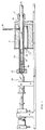
- Fig 1. is a schematic drawing of apparatus for heating an argon stream and for injection and vaporization of a sample into the argon stream.
- the sample feed stream is prepared for introduction to the plasma.
- Fig 2 illustrates a tube heater by which temperature of the sample feed stream is maintained in transit from the heating and sample injection apparatus shown in Fig 1. to the plasma torch.
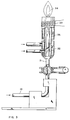
- Fig 3. is a schematic diagram of a plasma torch to illustrate the flow of sample feed into the torch.
- the argon heating and sample injection apparatus comprises a heating tube 10 which extends through a heating block 11 which is heated by an electric resistance heating rod 12.
- the heating tube extends outward from the block and is closed at its outer end by a septum cap 13.
- a sample feed tube 14 extends from its open end just short of the septum, concentrically through the length of the heating tube inside the heating block.
- the sample feed tube then continues from the heating block to the plasma torch.
- the outside diameter of the sample feed tube is smaller than the inside diameter of the heating tube, providing an annular path between the two tube walls for passage of argon.
- an argon supply tube 15 is connected into the heating tube and leads out of the heating block to an argon supply.
- the end of the heating tube inside the heating block connects to an annular fitting 16 which seals the inner end of the heating tube and leads through the wall of the block to the outside.
- the sample feed tube 14 extends from inside the heating tube through the center of the annular fitting 16 and through a sealing ring and gasket 17 which holds the feed tube in place and seals the end of the annular passage between the tubes. Argon flows from the supply tube through the annular passage towards the septum end of the heating tube.
- a syringe 18 containing the liquid sample to be tested has an injection needle 19 which extends from the syringe which is outside the tubes carrying the argon stream, through the septum cap and into the open end of the feed tube, to a point inside the feed tube and down stream from the heating tube.
- a small loose bundle of polytetuafluorethylene wool or metal fibers or wires is provided to dissipate liquid away from the needle end where the injected liquid might otherwise accumulate as droplets.
- the liquid sample to be analyzed is vaporized into the argon carrier gas in preparation for introduction to the plasma.
- An electric resistance heater in the heating block supplies heat to the heating tube and is regulated to maintain temperature of the heating tube wall at a selected temperature.
- a stream of argon gas is fed through the argon supply tube and into the annular passage between the heating tube and the sample feed tube. The argon is heated by contact with the hot tube walls as the gas flows through the annular passage. From the end of the annular passage, heated argon flows into the open end of the sample feed tube through which it continues its flow.
- a liquid sample in the syringe is introduced continuously at a regular rate through the injection needle into the heated argon stream which is flowing continuously through the sample feed tube.
- the injected liquid sample is rapidly heated and vaporized in the sample feed tube by heat from the hot argon gas stream and from the tube walls.
- the hot argon stream then carries the sample vapor through the feed tube and to the plasma torch for analysis.
- the sample feed tube continues from the heating and injection apparatus to the plasma torch.
- the length of the feed tube down stream from the injection point, and particularly between the heating block and the plasma, may be heated when necessary to maintain the temperature of the vapor-bearing gas to avoid condensation of the vapor.
- the ribbon 21 is heated by an electric power source not shown, connected to wire leads 23 which lead to resistance heating means in the ribbon.
- the heated cylinder 22 comprises two metal hemicylinders 24, each heated by an electric resistance rod 25 inside each of the hemicylinders. The two hemicylinders are fitted around the ribbon and clamped together to enclose the feed tube.
- thermostatic control means not shown electric power to resistance heaters in the ribbon and cylinder is regulated to maintain a selected temperature in the feed tube.
- a ball joint comprises a glass ball fitted tight between flared ends of the feed tube 14 and the sample feed passage 31 in the plasma torch. Heated argon gas carrying the sample vapor flows through a passage in the glass ball from the feed tube 14 into the sample feed passage 31 which leads through the torch to the plasma.
- the torch comprises a separate plasma gas passage 32 for supply of argon plasma gas which is heated in the torch by a radio frequency induction generator (RF coil) 33 to create the high temperature plasma 34 in which sample components are decomposed and metal atoms emit characteristic radiation which is detected and measured by the analyzer.
- the torch has still another argon passage 35 through which an auxiliary argon gas stream is directed to form an envelope of cooler gas surrounding the plasma.
- TMG trimethylgallium
- TMA trimethyl aluminum
- a standard solution is prepared with measured quantities of tetraethylsilicon, tetramethylgermanium and tetramethyltin in trimethylgallium.
- the apparatus described above and illustrated in the drawings is assembled.
- the sample feed tube and the argon pathway in the heating block are thoroughly cleaned and the sample feed tube is connected to the torch of the ICAP-61 analyzer at the ball joint.
- the heating elements are powered with electricity and regulated to maintain line temperature at 93°C.
- the plasma is ignited and operated with 1.50 Kw power to the RF coil, flowing 18 liters per minute of argon to the plasma gas stream, 1.1 liter per minute to the auxiliary gas stream and 0.65 liter per minute of argon to the sample gas stream.
- the torch is operated at these rates for at least 30 minutes to attain steady operation whereupon the analyzer is profiled and the vertical torch position is optimized by known procedures.
- a standard solution has been prepared of tetraethylsilicon, tetramethylgermanium and tetramethyltin in trimethylgallium. This solution has been made up to contain 13 micrograms/ml Ge, 16 micrograms/ml Sn and 11 micrograms/ml Si.
- a sample of pure liquid trimethylgallium is put into the syringe and injected at a rate of 0.1 ml/min per minute into the sample feed tube.
- the continuous stream of heated argon in the sample feed tube evaporates the trimethyl gallium sample and carries the vapor to the torch.
- the radiant emission from the plasma is monitored by the analyzer and the intensity at the characteristic wavelengths for germanium, tin and silicon are measured by the analyzer. A number of intensity measurements at each wavelength are automatically recorded and averaged for each wavelength.
- the sample feed tube is then purged and a new syringe containing the standard solution described above is used to inject the standard solution into the sample feed tube as before. Again the intensity at the wavelength for each metal is measured several times and averaged.
- the known metal content of each sample and the average intensities at wavelengths for each metal as measured for each of the two samples are used to plot an intensity vs. concentration calibration curve for each metal.
- sample solutions are prepared and used in the same manner except using trimethylaluminum instead of trimethylgallium, and the heating is adjusted to maintain line temperature in the sample feed tube at higher temperature, about 212°C, for analysis of trimethylaluminum.
- the analyzer may be calibrated in the same manner to analyze for other metals, using solutions of liquid compounds of such other metals in trimethylgallium or timethylaluminum for the calibration.
- the compounds can be injected and vaporized separately into the argon stream, each in a separate heater of the kind described and the vapors are then carried together in the stream to the torch.
- two heaters of the kind described above are connected in series with the argon stream from the first heater leading directly to the argon stream inlet of the second heater.
- a measured quantity of a liquid compound of an impurity metal is injected at a steady rate and vaporized in argon at the first heater and the vapor is carried by the argon stream into the second heater where a measured quantity of the second liquid is injected at steady rate and vaporized into the same argon stream which then carries both vapors to the torch.
- compounds such as dimethyl selenide, t-butylarsine, dimethylcadmium, or diethylsulfide, for example, can be vaporized in argon at the first heater and carried in the argon stream through the second heater where trimethylgallium or trimethylaluminum is vaporized and the stream proceeds to the plasma torch.
- the rate of delivery of gallium to the plasma amounts to about 1100 micrograms Ga per second.
- a typical delivery rate of gallium to the plasma using a 2% aqueous solution of a gallium compound delivered by a nebulizer amounts to about eight micrograms Ga per second.
- a typical delivery rate for feed of trimethyl gallium by the exponential dilution method amounts to about one microgram Ga per second.
- the limits of detection for metal impurities in the compounds can be reduced typically to less than one microgram per milliliter and, for most metals, in the range from 0.05 to 0.3 micrograms per milliliter.
- the apparatus and method of this invention can be used for analyzing other organometallic products for metal impurities, events in very small concentrations.
- monotertiary butyl arsine product may be analyzed for the presence of silicon, phosphorus and other metal impurities to limits less than one part per million.
Landscapes
- Physics & Mathematics (AREA)
- Health & Medical Sciences (AREA)
- Life Sciences & Earth Sciences (AREA)
- Chemical & Material Sciences (AREA)
- Analytical Chemistry (AREA)
- Biochemistry (AREA)
- General Health & Medical Sciences (AREA)
- General Physics & Mathematics (AREA)
- Immunology (AREA)
- Pathology (AREA)
- Engineering & Computer Science (AREA)
- Plasma & Fusion (AREA)
- Nuclear Medicine, Radiotherapy & Molecular Imaging (AREA)
- Investigating, Analyzing Materials By Fluorescence Or Luminescence (AREA)
- Other Investigation Or Analysis Of Materials By Electrical Means (AREA)
- Investigating Or Analysing Materials By Optical Means (AREA)
Applications Claiming Priority (2)
| Application Number | Priority Date | Filing Date | Title |
|---|---|---|---|
| US48540990A | 1990-02-27 | 1990-02-27 | |
| US485409 | 1990-02-27 |
Publications (3)
| Publication Number | Publication Date |
|---|---|
| EP0447747A2 EP0447747A2 (en) | 1991-09-25 |
| EP0447747A3 EP0447747A3 (en) | 1991-12-11 |
| EP0447747B1 true EP0447747B1 (en) | 1995-04-12 |
Family
ID=23928051
Family Applications (1)
| Application Number | Title | Priority Date | Filing Date |
|---|---|---|---|
| EP91100362A Expired - Lifetime EP0447747B1 (en) | 1990-02-27 | 1991-01-14 | Apparatus and method for injecting compounds in plasma for ICP-OES analysis |
Country Status (9)
| Country | Link |
|---|---|
| EP (1) | EP0447747B1 (da) |
| JP (1) | JPH04216440A (da) |
| KR (1) | KR0166375B1 (da) |
| AT (1) | ATE121190T1 (da) |
| CA (1) | CA2036988C (da) |
| DE (1) | DE69108763T2 (da) |
| DK (1) | DK0447747T3 (da) |
| ES (1) | ES2071125T3 (da) |
| GR (1) | GR3015860T3 (da) |
Cited By (1)
| Publication number | Priority date | Publication date | Assignee | Title |
|---|---|---|---|---|
| CN104034720A (zh) * | 2014-06-05 | 2014-09-10 | 同济大学 | 一种建筑废物中重金属检测方法 |
Families Citing this family (8)
| Publication number | Priority date | Publication date | Assignee | Title |
|---|---|---|---|---|
| JP3182913B2 (ja) * | 1992-04-23 | 2001-07-03 | 株式会社日立製作所 | 燃焼ガス中の金属成分計測方法及び装置 |
| DE19942519C1 (de) * | 1999-09-07 | 2001-06-13 | Degussa | Verfahren zur naßchemischen Bestimmung des Edelmetallgehaltes von Autoabgaskatalysatoren |
| KR100455655B1 (ko) * | 2002-01-25 | 2004-11-06 | 유일정공 주식회사 | 액상 시료 중금속 측정을 위한 표면 안정화 장치 |
| TW200407328A (en) * | 2002-09-19 | 2004-05-16 | Shinetsu Chemical Co | Liquid organometallic compound vaporizing/feeding system |
| JP3821227B2 (ja) * | 2002-09-19 | 2006-09-13 | 信越化学工業株式会社 | 有機金属化合物の気化供給装置 |
| CN101446556B (zh) * | 2007-05-25 | 2010-09-01 | 中国石化扬子石油化工有限公司 | 微波消解icp法测定催化重整催化剂中金属铂含量的方法 |
| JP6398206B2 (ja) * | 2013-02-21 | 2018-10-03 | 宇部興産株式会社 | 微量不純物を分析する方法、及び当該分析に用いるプラズマトーチ |
| CN110967334A (zh) * | 2019-12-18 | 2020-04-07 | 成都理工大学 | 一种地下水重金属监测方法及其装置 |
Family Cites Families (7)
| Publication number | Priority date | Publication date | Assignee | Title |
|---|---|---|---|---|
| US3824016A (en) * | 1972-06-16 | 1974-07-16 | R Woodriff | Combined sample collection and vaporization system for spectro-chemical analysis |
| AU518905B2 (en) * | 1977-10-18 | 1981-10-29 | Vari An Techtron Pty. Ltd | Spectroscopic analysis sample control |
| US4259573A (en) * | 1979-11-05 | 1981-03-31 | E. I. Du Pont De Nemours And Company | Method of determining small concentrations of chemical compounds by plasma chromatography |
| US4300393A (en) * | 1979-12-14 | 1981-11-17 | Stearns Stanley D | Sample introduction apparatus for gas chromatographic analysis using packed or capillary bore open tubular columns and method of testing |
| DE3026155A1 (de) * | 1980-07-10 | 1982-02-04 | Institut für Spektrochemie und angewandte Spektroskopie, 4600 Dortmund | Verfahren und vorrichtung zum einbringen einer probenfluessigkeit in feiner verteilung in eine anregungsquelle fuer spektroskopische zwecke |
| US4334882A (en) * | 1981-04-01 | 1982-06-15 | Mobil Oil Corporation | Determination of pyrite and siderite content of formation deposits |
| US4688935A (en) * | 1983-06-24 | 1987-08-25 | Morton Thiokol, Inc. | Plasma spectroscopic analysis of organometallic compounds |
-
1991
- 1991-01-14 DK DK91100362.2T patent/DK0447747T3/da active
- 1991-01-14 ES ES91100362T patent/ES2071125T3/es not_active Expired - Lifetime
- 1991-01-14 EP EP91100362A patent/EP0447747B1/en not_active Expired - Lifetime
- 1991-01-14 AT AT91100362T patent/ATE121190T1/de active
- 1991-01-14 DE DE69108763T patent/DE69108763T2/de not_active Expired - Fee Related
- 1991-02-25 CA CA002036988A patent/CA2036988C/en not_active Expired - Fee Related
- 1991-02-25 JP JP3050219A patent/JPH04216440A/ja active Pending
- 1991-02-26 KR KR1019910003125A patent/KR0166375B1/ko not_active Expired - Fee Related
-
1995
- 1995-04-19 GR GR940402765T patent/GR3015860T3/el unknown
Cited By (2)
| Publication number | Priority date | Publication date | Assignee | Title |
|---|---|---|---|---|
| CN104034720A (zh) * | 2014-06-05 | 2014-09-10 | 同济大学 | 一种建筑废物中重金属检测方法 |
| CN104034720B (zh) * | 2014-06-05 | 2016-08-17 | 同济大学 | 一种建筑废物中重金属检测方法 |
Also Published As
| Publication number | Publication date |
|---|---|
| EP0447747A2 (en) | 1991-09-25 |
| DE69108763D1 (de) | 1995-05-18 |
| JPH04216440A (ja) | 1992-08-06 |
| KR910021577A (ko) | 1991-12-20 |
| KR0166375B1 (ko) | 1999-05-01 |
| CA2036988A1 (en) | 1991-08-28 |
| ATE121190T1 (de) | 1995-04-15 |
| GR3015860T3 (en) | 1995-07-31 |
| DK0447747T3 (da) | 1996-02-05 |
| ES2071125T3 (es) | 1995-06-16 |
| EP0447747A3 (en) | 1991-12-11 |
| CA2036988C (en) | 2001-07-31 |
| DE69108763T2 (de) | 1995-08-24 |
Similar Documents
| Publication | Publication Date | Title |
|---|---|---|
| US4926021A (en) | Reactive gas sample introduction system for an inductively coupled plasma mass spectrometer | |
| Chong et al. | Inductively coupled plasma-mass spectrometry for elemental analysis and isotope ratio determinations in individual organic compounds separated by gas chromatography | |
| EP0447747B1 (en) | Apparatus and method for injecting compounds in plasma for ICP-OES analysis | |
| Goyette et al. | Swan band emission intensity as a function of density | |
| US6987565B2 (en) | Organometallic compound vaporizing/feeding system | |
| EP0132300B1 (en) | Plasma spectroscopic analysis of organometallic compound | |
| US20040056368A1 (en) | Liquid organometallic compound vaporizing/feeding system | |
| Persson et al. | Investigations of reactions involved in electro-thermal atomic absorption procedures: Part 8. A theoretical and experimental study of factors influencing the determination of phosphorus | |
| Kratzer et al. | In situ trapping of bismuthine in externally heated quartz tube atomizers for atomic absorption spectrometry | |
| US4225235A (en) | Sample introduction system for flameless emission spectroscopy | |
| US6236012B1 (en) | Plasma torch with an adjustable injector and gas analyzer using such a torch | |
| Sawhney et al. | Dissolution and elemental analysis of minerals, soils and environmental samples | |
| Goldfarb et al. | ICP-AES analysis of gases in energy technology and influence of molecular additives on argon ICP | |
| Vaccaro et al. | Laser spectroscopy of crossed molecular beams: The dissociation energy of BaI from energy‐balance measurements | |
| US20030133836A1 (en) | System for determining total sulfur content | |
| Alp et al. | In situ trapping of antimony hydride on iridium-coated tungsten coil and interference studies | |
| Kántor | Considerations in the gas flow design of a graphite furnace vaporization interface: effects of a halocarbon atmosphere and sample matrix. Invited lecture | |
| de Loos-Vollebregt et al. | Thermospray sample introduction into a horizontal low-flow inductively coupled plasma with end-on observation | |
| Capelle et al. | Metastable transfer emission spectroscopy—method and instrument for detection and measurement of trace materials in gas flows | |
| Kirschner et al. | First investigations for the development of a microwave-induced plasma atomic emission spectrometry system to determine trace metals in gases | |
| Imai et al. | Investigations of pyrolysed ascorbic acid in an electrothermal graphite furnace by inductively coupled argon plasma mass spectrometry and Raman spectrometry | |
| Hood et al. | Determination of sulfur-and phosphorus-containing compounds using metastable transfer emission spectrometry | |
| Jiménez et al. | On-line thermospray continuous volatilization of cobalt, aluminium and chromium volatile chelates and determination by heated quartz tube atomic absorption spectrometry | |
| Johansson et al. | Mechanism of formation and spatial distribution of lead atoms in quartz tube atomizers | |
| Dědina et al. | On-line atomization of selenium hydride in graphite furnaces: estimate of atomic absorption coefficient and spectroscopic temperature |
Legal Events
| Date | Code | Title | Description |
|---|---|---|---|
| PUAI | Public reference made under article 153(3) epc to a published international application that has entered the european phase |
Free format text: ORIGINAL CODE: 0009012 |
|
| AK | Designated contracting states |
Kind code of ref document: A2 Designated state(s): AT BE CH DE DK ES FR GB GR IT LI LU NL SE |
|
| PUAL | Search report despatched |
Free format text: ORIGINAL CODE: 0009013 |
|
| AK | Designated contracting states |
Kind code of ref document: A3 Designated state(s): AT BE CH DE DK ES FR GB GR IT LI LU NL SE |
|
| RHK1 | Main classification (correction) |
Ipc: G01N 21/35 |
|
| 17P | Request for examination filed |
Effective date: 19920506 |
|
| 17Q | First examination report despatched |
Effective date: 19940520 |
|
| RAP1 | Party data changed (applicant data changed or rights of an application transferred) |
Owner name: CYTEC TECHNOLOGY CORP. |
|
| GRAA | (expected) grant |
Free format text: ORIGINAL CODE: 0009210 |
|
| AK | Designated contracting states |
Kind code of ref document: B1 Designated state(s): AT BE CH DE DK ES FR GB GR IT LI LU NL SE |
|
| REF | Corresponds to: |
Ref document number: 121190 Country of ref document: AT Date of ref document: 19950415 Kind code of ref document: T |
|
| REF | Corresponds to: |
Ref document number: 69108763 Country of ref document: DE Date of ref document: 19950518 |
|
| ET | Fr: translation filed | ||
| REG | Reference to a national code |
Ref country code: ES Ref legal event code: FG2A Ref document number: 2071125 Country of ref document: ES Kind code of ref document: T3 |
|
| REG | Reference to a national code |
Ref country code: GR Ref legal event code: FG4A Free format text: 3015860 |
|
| ITF | It: translation for a ep patent filed | ||
| REG | Reference to a national code |
Ref country code: DK Ref legal event code: T3 |
|
| PLBE | No opposition filed within time limit |
Free format text: ORIGINAL CODE: 0009261 |
|
| STAA | Information on the status of an ep patent application or granted ep patent |
Free format text: STATUS: NO OPPOSITION FILED WITHIN TIME LIMIT |
|
| 26N | No opposition filed | ||
| PGFP | Annual fee paid to national office [announced via postgrant information from national office to epo] |
Ref country code: GB Payment date: 20001211 Year of fee payment: 11 Ref country code: DK Payment date: 20001211 Year of fee payment: 11 |
|
| PGFP | Annual fee paid to national office [announced via postgrant information from national office to epo] |
Ref country code: AT Payment date: 20001212 Year of fee payment: 11 |
|
| PGFP | Annual fee paid to national office [announced via postgrant information from national office to epo] |
Ref country code: NL Payment date: 20001222 Year of fee payment: 11 |
|
| PGFP | Annual fee paid to national office [announced via postgrant information from national office to epo] |
Ref country code: SE Payment date: 20010103 Year of fee payment: 11 Ref country code: FR Payment date: 20010103 Year of fee payment: 11 |
|
| PGFP | Annual fee paid to national office [announced via postgrant information from national office to epo] |
Ref country code: ES Payment date: 20010123 Year of fee payment: 11 |
|
| PGFP | Annual fee paid to national office [announced via postgrant information from national office to epo] |
Ref country code: LU Payment date: 20010124 Year of fee payment: 11 |
|
| PGFP | Annual fee paid to national office [announced via postgrant information from national office to epo] |
Ref country code: DE Payment date: 20010126 Year of fee payment: 11 |
|
| PGFP | Annual fee paid to national office [announced via postgrant information from national office to epo] |
Ref country code: GR Payment date: 20010129 Year of fee payment: 11 |
|
| PGFP | Annual fee paid to national office [announced via postgrant information from national office to epo] |
Ref country code: BE Payment date: 20010326 Year of fee payment: 11 |
|
| PGFP | Annual fee paid to national office [announced via postgrant information from national office to epo] |
Ref country code: CH Payment date: 20010327 Year of fee payment: 11 |
|
| REG | Reference to a national code |
Ref country code: GB Ref legal event code: IF02 |
|
| PG25 | Lapsed in a contracting state [announced via postgrant information from national office to epo] |
Ref country code: LU Free format text: LAPSE BECAUSE OF NON-PAYMENT OF DUE FEES Effective date: 20020114 Ref country code: GB Free format text: LAPSE BECAUSE OF NON-PAYMENT OF DUE FEES Effective date: 20020114 Ref country code: AT Free format text: LAPSE BECAUSE OF NON-PAYMENT OF DUE FEES Effective date: 20020114 |
|
| PG25 | Lapsed in a contracting state [announced via postgrant information from national office to epo] |
Ref country code: SE Free format text: LAPSE BECAUSE OF NON-PAYMENT OF DUE FEES Effective date: 20020115 Ref country code: ES Free format text: LAPSE BECAUSE OF NON-PAYMENT OF DUE FEES Effective date: 20020115 |
|
| PG25 | Lapsed in a contracting state [announced via postgrant information from national office to epo] |
Ref country code: LI Free format text: LAPSE BECAUSE OF NON-PAYMENT OF DUE FEES Effective date: 20020131 Ref country code: DK Free format text: LAPSE BECAUSE OF NON-PAYMENT OF DUE FEES Effective date: 20020131 Ref country code: CH Free format text: LAPSE BECAUSE OF NON-PAYMENT OF DUE FEES Effective date: 20020131 Ref country code: BE Free format text: LAPSE BECAUSE OF NON-PAYMENT OF DUE FEES Effective date: 20020131 |
|
| BERE | Be: lapsed |
Owner name: CYTEC TECHNOLOGY CORP. Effective date: 20020131 |
|
| PG25 | Lapsed in a contracting state [announced via postgrant information from national office to epo] |
Ref country code: NL Free format text: LAPSE BECAUSE OF NON-PAYMENT OF DUE FEES Effective date: 20020801 Ref country code: DE Free format text: LAPSE BECAUSE OF NON-PAYMENT OF DUE FEES Effective date: 20020801 |
|
| PG25 | Lapsed in a contracting state [announced via postgrant information from national office to epo] |
Ref country code: GR Free format text: LAPSE BECAUSE OF NON-PAYMENT OF DUE FEES Effective date: 20020812 |
|
| EUG | Se: european patent has lapsed |
Ref document number: 91100362.2 |
|
| GBPC | Gb: european patent ceased through non-payment of renewal fee |
Effective date: 20020114 |
|
| REG | Reference to a national code |
Ref country code: CH Ref legal event code: PL |
|
| PG25 | Lapsed in a contracting state [announced via postgrant information from national office to epo] |
Ref country code: FR Free format text: LAPSE BECAUSE OF NON-PAYMENT OF DUE FEES Effective date: 20020930 |
|
| NLV4 | Nl: lapsed or anulled due to non-payment of the annual fee |
Effective date: 20020801 |
|
| REG | Reference to a national code |
Ref country code: DK Ref legal event code: EBP |
|
| REG | Reference to a national code |
Ref country code: FR Ref legal event code: ST |
|
| REG | Reference to a national code |
Ref country code: ES Ref legal event code: FD2A Effective date: 20030922 |
|
| PG25 | Lapsed in a contracting state [announced via postgrant information from national office to epo] |
Ref country code: IT Free format text: LAPSE BECAUSE OF NON-PAYMENT OF DUE FEES Effective date: 20050114 |