EP0447772B1 - Bandsaw guide - Google Patents
Bandsaw guide Download PDFInfo
- Publication number
- EP0447772B1 EP0447772B1 EP91101403A EP91101403A EP0447772B1 EP 0447772 B1 EP0447772 B1 EP 0447772B1 EP 91101403 A EP91101403 A EP 91101403A EP 91101403 A EP91101403 A EP 91101403A EP 0447772 B1 EP0447772 B1 EP 0447772B1
- Authority
- EP
- European Patent Office
- Prior art keywords
- saw band
- band
- guide
- plates
- saw
- Prior art date
- Legal status (The legal status is an assumption and is not a legal conclusion. Google has not performed a legal analysis and makes no representation as to the accuracy of the status listed.)
- Expired - Lifetime
Links
- 239000002184 metal Substances 0.000 claims description 13
- 239000000463 material Substances 0.000 claims description 12
- 230000003116 impacting effect Effects 0.000 claims 1
- 238000005520 cutting process Methods 0.000 description 3
- 241000251468 Actinopterygii Species 0.000 description 1
- 230000006978 adaptation Effects 0.000 description 1
- 230000000694 effects Effects 0.000 description 1
- 235000013611 frozen food Nutrition 0.000 description 1
Images
Classifications
-
- B—PERFORMING OPERATIONS; TRANSPORTING
- B23—MACHINE TOOLS; METAL-WORKING NOT OTHERWISE PROVIDED FOR
- B23D—PLANING; SLOTTING; SHEARING; BROACHING; SAWING; FILING; SCRAPING; LIKE OPERATIONS FOR WORKING METAL BY REMOVING MATERIAL, NOT OTHERWISE PROVIDED FOR
- B23D55/00—Sawing machines or sawing devices working with strap saw blades, characterised only by constructional features of particular parts
- B23D55/08—Sawing machines or sawing devices working with strap saw blades, characterised only by constructional features of particular parts of devices for guiding or feeding strap saw blades
- B23D55/082—Devices for guiding strap saw blades
-
- B—PERFORMING OPERATIONS; TRANSPORTING
- B23—MACHINE TOOLS; METAL-WORKING NOT OTHERWISE PROVIDED FOR
- B23Q—DETAILS, COMPONENTS, OR ACCESSORIES FOR MACHINE TOOLS, e.g. ARRANGEMENTS FOR COPYING OR CONTROLLING; MACHINE TOOLS IN GENERAL CHARACTERISED BY THE CONSTRUCTION OF PARTICULAR DETAILS OR COMPONENTS; COMBINATIONS OR ASSOCIATIONS OF METAL-WORKING MACHINES, NOT DIRECTED TO A PARTICULAR RESULT
- B23Q11/00—Accessories fitted to machine tools for keeping tools or parts of the machine in good working condition or for cooling work; Safety devices specially combined with or arranged in, or specially adapted for use in connection with, machine tools
- B23Q11/02—Devices for removing scrap from the cutting teeth of circular or non-circular cutters
-
- Y—GENERAL TAGGING OF NEW TECHNOLOGICAL DEVELOPMENTS; GENERAL TAGGING OF CROSS-SECTIONAL TECHNOLOGIES SPANNING OVER SEVERAL SECTIONS OF THE IPC; TECHNICAL SUBJECTS COVERED BY FORMER USPC CROSS-REFERENCE ART COLLECTIONS [XRACs] AND DIGESTS
- Y10—TECHNICAL SUBJECTS COVERED BY FORMER USPC
- Y10T—TECHNICAL SUBJECTS COVERED BY FORMER US CLASSIFICATION
- Y10T83/00—Cutting
- Y10T83/202—With product handling means
- Y10T83/2092—Means to move, guide, or permit free fall or flight of product
- Y10T83/2209—Guide
-
- Y—GENERAL TAGGING OF NEW TECHNOLOGICAL DEVELOPMENTS; GENERAL TAGGING OF CROSS-SECTIONAL TECHNOLOGIES SPANNING OVER SEVERAL SECTIONS OF THE IPC; TECHNICAL SUBJECTS COVERED BY FORMER USPC CROSS-REFERENCE ART COLLECTIONS [XRACs] AND DIGESTS
- Y10—TECHNICAL SUBJECTS COVERED BY FORMER USPC
- Y10T—TECHNICAL SUBJECTS COVERED BY FORMER US CLASSIFICATION
- Y10T83/00—Cutting
- Y10T83/707—By endless band or chain knife
- Y10T83/7264—With special blade guide means
Definitions
- the invention relates to a saw band guide consisting of a support elements supporting the saw band on the toothless trailing edge thereof, in particular a support roller, and a guide fork, between the fork branches of which the saw band is guided by hard metal bodies which are fastened as plates with large support surfaces facing one another, as plates with mutually facing large support surfaces.
- the front edge of the plates facing the direction of the strip form an obtuse angle with the saw band.
- Band saws are used for portioning frozen food blocks, especially frozen fish blocks.
- the saw bands In order not to have to accept a high cut loss when using such band saws and to obtain portions with small weight tolerances, the saw bands not only have to be very thin, but also flutter-free as close as possible to the block.
- the fork branches are each equipped with a narrow hard metal body arranged at an angle to the running direction of the saw band, the two hard metal bodies being arranged crosswise to one another. When operating such a saw band guide, it was found that the hard metal bodies and the band are subject to increased wear in the region of the crossing point. This wear leads to a reduction in the lateral guidance of the saw band, which is not optimal from the start anyway.
- the invention has for its object to provide a saw band guide that gives the saw band a very precise lateral guidance over a long period of operation.
- the material to be cut during sawing should not impair the cutting area.
- the guide fork adjacent to the rear edge of the saw band has a free space, and that the front edges of the plates lying in the plane of the support surfaces of the plates, are aligned at an obtuse angle to the front edge of the saw band carrying the teeth and a guide for the material that strikes the front edges of the plates and is stripped from the saw band along the front edges of the plates into the free space.
- this saw band guide In contrast to the known saw band guide, this saw band guide not only guides the saw band selectively, but also over a large area.
- the orientation of the front edges ensures that a force component acts against the support element when the saw band runs, so that there is also no danger that the band will lift off the support element.
- the special orientation of the leading edges in connection with the narrow, flat band guide means that the material to be cut adhering to the saw band is largely stripped and diverted and does not get between the plates.
- the derived material to be cut is guided towards the rear edge of the belt, where there is enough space between the fork branches for further removal of the material to be cut without the risk of clogging.
- the wiping effect of the front edges of the panels with respect to that adhering to the saw band Cuttings can be further improved in that the front edges are chamfered to the side facing away from the saw band.
- Triangular plates are preferably used as the hard metal body.
- the guide gap between the plates has particularly close tolerances if, according to one embodiment of the invention, the plates consist of a block anchored between the fork branches, which is severed in the middle to form the guide gap for the saw band, in particular by means of a laser beam.
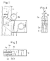
- the saw band guide for a saw band 1 shown in the drawing is arranged in a holder, not shown. It consists of a guide fork 2 and a support roller 3.
- the toothed band 1 is supported with its toothless rear edge in a groove 3a of the support roller 3.
- the guide fork 2 has two fork branches 2a, 2b, which are equipped on the inside with triangular hard metal plates 4a, 4b. These hard metal plates 4a, 4b are on the Fork branches 2a, 2b soldered. They are made from a soldered block, which is cut through a laser beam to form a guide gap 4c.
- the fork branches 2a, 2b with the soldered plates 4a, 4b are angled upward against the running direction L of the saw band 1.
- each plate 4a, 4b adjacent to the saw teeth parallel to the saw teeth and the front edge 4a ', 4b' of each plate 4a, 4b facing the direction of travel form an obtuse angle with the direction of travel L.
- the plates 4a, 4b are beveled towards the rear on their edge surfaces 4d, which are in particular adjacent to the front edges 4a ', 4b', which above all makes it easier to strip off the material to be cut which is adhering to the saw band.
- the stripped material to be cut is conveyed in the direction of the rear edge of the saw band 1, where it is conveyed through the wide free space 2c between the fork branches 2a, 2b.
Landscapes
- Engineering & Computer Science (AREA)
- Mechanical Engineering (AREA)
- Sawing (AREA)
- Polishing Bodies And Polishing Tools (AREA)
Description
Die Erfindung betrifft eine Sägebandführung bestehend aus einem das Sägeband an dessen zahnloser Hinterkante abstützenden Stützelemente, insbesondere Stützrolle, und einer Führungsgabel, zwischen deren Gabelästen das Sägeband unter Anlage an innenseitig an den Kabelästen befestigten, als Platten mit einander zugekehrten großflächigen Stützflächen ausgebildeten Hartmetallkörpern geführt ist, wobei die der Bandlaufrichtung zugekehrte Vorderkante der Platten mit dem Sägeband einen stumpfen Winkel einschließen. Eine solche Sägebandführung ist vom Stand der Technik bekannt.The invention relates to a saw band guide consisting of a support elements supporting the saw band on the toothless trailing edge thereof, in particular a support roller, and a guide fork, between the fork branches of which the saw band is guided by hard metal bodies which are fastened as plates with large support surfaces facing one another, as plates with mutually facing large support surfaces. the front edge of the plates facing the direction of the strip form an obtuse angle with the saw band. Such a saw band guide is known from the prior art.
Beim Portionieren von tiefgefrorenen Lebensmittelblöcken, insbesondere tiefgefrorenen Fischblöcken, werden Bandsägen eingesetzt. Um beim Einsatz solcher Bandsägen keinen hohen Schnittverlust in Kauf nehmen zu müssen und um Portionen mit kleinen Gewichtstoleranzen zu erhalten, müssen die Sägebänder nicht nur sehr dünn sein, sondern auch flatterfrei möglichst nahe am Block geführt werden. Bei einer aus der Praxis bekannten Sägebandführung der eingangs genannten Art werden diese Forderungen nicht optimal erfüllt. Die Gabeläste sind jeweils mit einem schmalen, geneigt zur Laufrichtung des Sägebandes angeordneten Hartmetallkörper bestückt, wobei die beiden Hartmetallkörper zueinander über Kreuz angeordnet sind. Beim Betrieb einer solchen Sägebandführung wurde festgestellt, daß die Hartmetallkörper und das Band im Bereich des Kreuzungspunktes einem erhöhten Verschleiß unterliegen. Dieser Verschleiß führt zu einer Verminderung der ohnehin von Anfang an nicht optimalen Seitenführung des Sägebandes.Band saws are used for portioning frozen food blocks, especially frozen fish blocks. In order not to have to accept a high cut loss when using such band saws and to obtain portions with small weight tolerances, the saw bands not only have to be very thin, but also flutter-free as close as possible to the block. In a saw blade guide of the type mentioned at the outset, these requirements are not optimally met. The fork branches are each equipped with a narrow hard metal body arranged at an angle to the running direction of the saw band, the two hard metal bodies being arranged crosswise to one another. When operating such a saw band guide, it was found that the hard metal bodies and the band are subject to increased wear in the region of the crossing point. This wear leads to a reduction in the lateral guidance of the saw band, which is not optimal from the start anyway.
Aber nicht nur zu diesem Zweck, sondern auch zu anderen Zwecken werden Seitenführungen des Sägebandes verwendet. Bei einem bekannten Sägeband (DE-A-36 23 962) sind zwei Sägebandführungen der eingangs genannten Art mit Abstand voneinander angeordnet, um das über Rollen geführte Sägeband um 90o zu verdrillen und danach wieder zurück zu verdrillen, damit es in dem Bereich zwischen den beiden Sägebandführungen mit seiner gezahnten Vorderkante dem Schneidgut zugekehrt ist. In diesem Fall dient die Anordnung der Vorderkante des Hartmetallkörpers der in Bandlaufrichtung ersten Sägebandführung und der Hinterkante des Hartmetallkörpers deren Bandlaufrichtung zweiten Sägebandführung der geometrischen Anpassung an das verdrillte Band.But not only for this purpose, but also for other purposes, side guides of the saw band are used. In one prior art band saw blade (DE-A-36 23 962), two blade guides of the type mentioned are spaced from each other to the guided over rollers saw blade to be twisted by 90 ° and then be twisted back again, so that it's in the range between two saw band guides with its toothed front edge facing the material to be cut. In this case, the arrangement of the front edge of the hard metal body of the first saw band guide in the band running direction and the rear edge of the hard metal body of the band saw direction of the second saw band guide serve for the geometrical adaptation to the twisted band.
Bei einer anderen bekannten Sägebandführung (DE-U-82 28 862.3), bei der das Sägeband nicht verdrillt wird, wird es zwischen den Gabelästen eines Blockes unter rückseitiger Abstützung an einem Einsatz aus Hartmetall geführt. Damit das zerspante Gut nicht in den Bereich der Abstützung gelangt, sind die Gabeläste an ihren Vorderkanten derart schräg ausgebildet, daß das zerspante Gut in Richtung des Schnittes geführt wird. Ein derartiger Abtransport des zerspanten Gutes kann zu Störungen an der Schnittkante führen.In another known saw band guide (DE-U-82 28 862.3), in which the saw band is not twisted, it is guided between the fork branches of a block with rear support on an insert made of hard metal. So that the machined material does not reach the area of the support, the fork branches are so inclined at their front edges that the machined material in Direction of the cut is performed. Such removal of the machined material can lead to faults at the cutting edge.
Der Erfindung liegt die Aufgabe zugrunde, eine Sägebandführung zu schaffen, die über eine lange Betriebsdauer dem Sägeband eine sehr präzise seitliche Führung gibt. Dabei soll insbesondere das beim Sägen anfallende zerspante Gut nicht im Schnittbereich beeinträchtigen.The invention has for its object to provide a saw band guide that gives the saw band a very precise lateral guidance over a long period of operation. In particular, the material to be cut during sawing should not impair the cutting area.
Diese Aufgabe wird erfindungsgemäß dadurch gelöst, daß die Führungsgabel benachbart zu der Hinterkante des Sägebandes einen Freiraum aufweist, und daß die Vorderkanten der Platten in der Ebene der Stützflächen der Platten liegend, im stumpfen Winkel zur die Zähne tragenden Vorderkante des Sägebandes ausgerichtet sind und eine Führung für das auf die Vorderkanten der Platten treffende, vom Sägeband abgestreifte Gut entlang der Vorderkanten der Platten in den Freiraum bilden.This object is achieved in that the guide fork adjacent to the rear edge of the saw band has a free space, and that the front edges of the plates lying in the plane of the support surfaces of the plates, are aligned at an obtuse angle to the front edge of the saw band carrying the teeth and a guide for the material that strikes the front edges of the plates and is stripped from the saw band along the front edges of the plates into the free space.
Bei dieser Sägebandführung wird im Unterschied zu der bekannten Sägebandführung das Sägeband nicht nur punktuell, sondern großflächig geführt. Aufgrund der Orientierung der Vorderkanten ist gewährleistet, daß sich beim Lauf des Sägebandes eine gegen das Stützelement wirkende Kraftkomponente einstellt, so daß auch keine Gefahr besteht, daß das Band von dem Stützelement abhebt. Darüber hinaus wird durch die besondere Orientierung der Vorderkanten in Verbindung mit der engen flächigen Bandführung erreicht, daß am Sägeband haftendes Schneidgut weitgehend abgestreift und abgeleitet wird und nicht zwischen die Platten gelangt. Das abgeleitete Schneidgut wird in Richtung der Bandhinterkante geführt, wo zwischen den Gabelästen genügend Raum für die weitere Abfuhr des Schneidgutes ohne Verstopfungsgefahr zur Verfügung steht. Der Abstreifeffekt der Vorderkanten der Platten bezüglich des auf dem Sägeband haftenden Schneidgutes kann weiter noch dadurch verbessert werden, daß die Vorderkanten zu der dem Sägeband abgewandten Seite abgeschrägt sind.In contrast to the known saw band guide, this saw band guide not only guides the saw band selectively, but also over a large area. The orientation of the front edges ensures that a force component acts against the support element when the saw band runs, so that there is also no danger that the band will lift off the support element. In addition, the special orientation of the leading edges in connection with the narrow, flat band guide means that the material to be cut adhering to the saw band is largely stripped and diverted and does not get between the plates. The derived material to be cut is guided towards the rear edge of the belt, where there is enough space between the fork branches for further removal of the material to be cut without the risk of clogging. The wiping effect of the front edges of the panels with respect to that adhering to the saw band Cuttings can be further improved in that the front edges are chamfered to the side facing away from the saw band.
Bevorzugt werden als Hartmetallkörper dreieckige Platten eingesetzt. Der Führungsspalt zwischen den Platten hat besonders enge Toleranzen, wenn nach einer Ausgestaltung der Erfindung die Platten aus einem zwischen den Gabelästen verankerten Block bestehen, der mittig zur Bildung des Führungsspaltes für das Sägeband, insbesondere mittels eines Laserstrahls, durchtrennt ist.Triangular plates are preferably used as the hard metal body. The guide gap between the plates has particularly close tolerances if, according to one embodiment of the invention, the plates consist of a block anchored between the fork branches, which is severed in the middle to form the guide gap for the saw band, in particular by means of a laser beam.
Im folgenden wird die Erfindung anhand einer ein Ausführungsbeispiel darstellenden Zeichnung näher erläutert. Im einzelnen zeigen:
- Figur 1
- eine Sägebandführung bestehend aus Stützrolle und Führungsgabel in Seitenansicht,
Figur 2- die Führungsgabel der Sägebandführung gemäß Figur 1 in Aufsicht
und - Figur 3
- die Führungsgabel der Sägebandführung gemäß Figur 1 in Vorderansicht.
- Figure 1
- a saw band guide consisting of support roller and guide fork in side view,
- Figure 2
- the guide fork of the saw band guide according to Figure 1 in supervision
and - Figure 3
- the guide fork of the saw band guide according to Figure 1 in front view.
Die in der Zeichnung dargestellte Sägebandführung für ein Sägeband 1 ist in einem nicht dargestellten Halter angeordnet. Sie besteht aus einer Führungsgabel 2 und einer Stützrolle 3. Das Sägeband 1 ist mit seiner zahnlosen Hinterkante in einer Nut 3a der Stützrolle 3 abgestützt. Die Führungsgabel 2 weist zwei Gabeläste 2a,2b auf, die innenseitig mit dreieckigen Hartmetallplatten 4a,4b bestückt sind. Diese Hartmetallplatten 4a,4b sind an den Gabelästen 2a,2b angelötet. Sie sind aus einem angelöteten Block gefertigt, der zur Bildung eines Führungsspaltes 4c mittels eines Laserstrahls durchtrennt ist. Die Gabeläste 2a,2b mit den angelöteten Platten 4a,4b sind entgegen der Laufrichtung L des Sägebandes 1 nach oben abgewinkelt. Dabei ergibt sich eine geometrische Konfiguration, bei der die den Sägezähnen benachbarte Kante einer jeden Platte 4a,4b parallel zu den Sägezähnen und die der Laufrichtung zugekehrte Vorderkante 4a',4b' einer jeden Platte 4a,4b mit der Laufrichtung L einen stumpfen Winkel einschließt. Die Platten 4a,4b sind an ihren insbesondere an die Vorderkanten 4a',4b' angrenzenden Kantenflächen 4d zur Rückseite abgeschrägt, wodurch vor allem das Abstreifen von am Sägeband haftendem Schneidgut erleichtert wird. Das abgestreifte Schneidgut wird in Richtung der Hinterkante des Sägebandes 1 gefördert, wo es durch den breiten Freiraum 2c zwischen den Gabelästen 2a,2b abgefördert wird.The saw band guide for a saw band 1 shown in the drawing is arranged in a holder, not shown. It consists of a
Claims (5)
- A saw band guide, comprising a supporting element, more particularly a supporting roller (3) supporting the unserrated rear edge of the saw band (1), and a guide fork (2) between whose fork branches (2a, 2b), fitted on the inside with hard metal bodies (4a, 4b), the saw band (1) is guided with its sides bearing against the hard metal bodies (4a, 4b), taking the form of plates having large-area bearing surfaces one another, their front edges (4a', 4b') facing the direction in which the saw band (1) runs enclosing an obtuse angle therewith, characterized- in that the guide fork (2) has an opening (2c) adjacent to the rear edge of the band (1),- and front edges of the plates 4a, 4b lie in the plane of the bearing surfaces and enclose the obtuse angle teeth bearing front edge of the band and form a guidance for the sawn material impacting the front edges (4a', 4b') of the plates (4a, 4b) and stripped off the saw band (1) along the plate front edges (4a', 4b') into the opening (2c).
- A saw band guide according to claim 1, characterized in that the edge areas (4a) adjacent to the front edges (4a', 4b') are chamfered towards the side remote from the saw band (1).
- A saw band guide according to claims 1 or 2, characterized in that the hard metal bodies (4a, 4b) are triangular plates.
- A saw band guide according to claims 1 or 2, characterized in that the fork branches (2a, 2b) are bent oppositely to the direction (L) in which the band runs, and the bearing element (3) is disposed behind the bent fork branches (2a, 2b).
- A saw band guide according to one of claims 1 to 4, characterized in that the plates (4a, 4b) consist of a block which is anchored between the fork branches (2a, 2b) and is parted in the centre, more particularly by means of a laser beam, to form the guide gap (4c) for the saw band (1).
Applications Claiming Priority (2)
| Application Number | Priority Date | Filing Date | Title |
|---|---|---|---|
| DE4009405 | 1990-03-23 | ||
| DE4009405A DE4009405A1 (en) | 1990-03-23 | 1990-03-23 | SAW BAND GUIDE |
Publications (2)
| Publication Number | Publication Date |
|---|---|
| EP0447772A1 EP0447772A1 (en) | 1991-09-25 |
| EP0447772B1 true EP0447772B1 (en) | 1995-05-24 |
Family
ID=6402934
Family Applications (1)
| Application Number | Title | Priority Date | Filing Date |
|---|---|---|---|
| EP91101403A Expired - Lifetime EP0447772B1 (en) | 1990-03-23 | 1991-02-02 | Bandsaw guide |
Country Status (5)
| Country | Link |
|---|---|
| US (1) | US5119705A (en) |
| EP (1) | EP0447772B1 (en) |
| DE (2) | DE4009405A1 (en) |
| DK (1) | DK0447772T3 (en) |
| NO (1) | NO178255C (en) |
Families Citing this family (16)
| Publication number | Priority date | Publication date | Assignee | Title |
|---|---|---|---|---|
| DE9307181U1 (en) * | 1993-05-07 | 1993-09-23 | Interholz Technik GmbH, 79108 Freiburg | BAND SAW BLADE GUIDE |
| DE19612029C1 (en) * | 1996-03-27 | 1997-07-10 | Nienstedt Heinz Maschf | Process and assembly reduces blocks of frozen fish to fish fingers |
| US6463836B1 (en) | 1999-02-01 | 2002-10-15 | Howard L. Snodgrass, Jr. | Guide for band saws |
| US6272964B1 (en) | 2000-01-04 | 2001-08-14 | Torben Heilshov | Band saw blade guide |
| US20020088329A1 (en) * | 2001-01-05 | 2002-07-11 | Torben Helshoj | Band saw blade stabilizer |
| US20040261593A1 (en) * | 2003-06-28 | 2004-12-30 | Gallagher Michael Edward | Scoll saw table insert blade positioner |
| US7739937B2 (en) * | 2006-05-01 | 2010-06-22 | Pollard Sr Albert Clarkson | Band saw blade guide |
| US9827623B2 (en) | 2007-09-21 | 2017-11-28 | Black & Decker Inc. | Control of reciprocation speed and orbital magnitude of a jigsaw with a plurality of material and/or task descriptive icons |
| US10029322B2 (en) * | 2007-09-21 | 2018-07-24 | Black & Decker Inc. | Housing of a cutting tool including blade storage, integral blade guard and motor ventilation pathway |
| US8033026B2 (en) * | 2007-09-21 | 2011-10-11 | Black & Decker Inc. | Adjustable and removable keel assembly and blade guide for a jigsaw |
| US20090077819A1 (en) * | 2007-09-21 | 2009-03-26 | Black & Decker Inc. | Cutting Angle Indicator in Jigsaw Housing with Positive Lock in Separately Assembled Shoe Sub-Assembly |
| US9981327B2 (en) * | 2007-09-21 | 2018-05-29 | Black & Decker Inc. | Cutting angle indicator in jigsaw housing with dust extraction |
| DE102008044669B4 (en) * | 2008-08-28 | 2020-03-26 | Keuro Besitz Gmbh & Co. Edv-Dienstleistungs Kg | Guide for a saw band or a saw blade of a sawing machine |
| DE102010052633B4 (en) * | 2010-11-29 | 2013-06-27 | Gebrüder Linck Maschinenfabrik "Gatterlinck" GmbH & Co KG | band saw |
| US8578615B2 (en) | 2011-09-12 | 2013-11-12 | Black & Decker Inc. | Jigsaw with deployable keel and tiltable shoe |
| US9559628B2 (en) | 2013-10-25 | 2017-01-31 | Black & Decker Inc. | Handheld power tool with compact AC switch |
Family Cites Families (20)
| Publication number | Priority date | Publication date | Assignee | Title |
|---|---|---|---|---|
| US425105A (en) * | 1890-04-08 | Guide for band-saws | ||
| DE8228862U1 (en) * | 1983-01-27 | Karl M. Reich Maschinenfabrik GmbH, 7440 Nürtingen | Band guide for band saws | |
| US1870774A (en) * | 1930-10-22 | 1932-08-09 | Atlas Mfg Company | Power meat saw |
| US2311426A (en) * | 1939-10-23 | 1943-02-16 | Leighton A Wilkie | Sawing apparatus |
| US2741281A (en) * | 1952-02-07 | 1956-04-10 | Toledo Scale Co | Band saw blade scraper |
| US2850053A (en) * | 1955-04-27 | 1958-09-02 | Herman J Voss | Block band saw mill |
| US3109465A (en) * | 1961-05-19 | 1963-11-05 | Sure Hit Products Inc | Saw guide assemblies |
| US3280862A (en) * | 1964-04-07 | 1966-10-25 | Joseph J Foley | Bearing for power band meat saw |
| US3530752A (en) * | 1967-03-14 | 1970-09-29 | Amada Co Ltd | Guiding and vibration damping device for a saw blade in a band-sawing machine |
| DE2144133C3 (en) * | 1971-09-03 | 1978-05-24 | Fortuna-Werke Maschinenfabrik Gmbh, 7000 Stuttgart | Band knife guide on band knife splitting machines |
| US3689168A (en) * | 1971-12-30 | 1972-09-05 | Henry Persson | Mountable chip breaker and flute cleaner for rotating twist drills |
| US3872762A (en) * | 1973-09-04 | 1975-03-25 | Hoe & Co R | Band saw system |
| JPS5837541Y2 (en) * | 1979-02-06 | 1983-08-24 | 株式会社アマダ | Band saw blade guide device |
| DE3241471A1 (en) * | 1982-11-10 | 1984-05-10 | Johannes 7953 Bad Schussenried Falkenstein | Bandsaw |
| DE3467087D1 (en) * | 1984-03-02 | 1987-12-10 | Frisco Findus Ag | Utlisation of fish waste |
| US4648301A (en) * | 1985-05-20 | 1987-03-10 | L Investments, Ltd. | Adapter for circular saw to cut-off saw |
| FR2622832B2 (en) * | 1985-12-30 | 1991-05-17 | Valentin Bernard | SAW, CHIP AND DUST EJECTOR DEVICE FOR BAND SAW |
| DE3623962A1 (en) * | 1986-07-16 | 1988-01-28 | Leopold Jaegers | Band sawing machine |
| DE3725361A1 (en) * | 1987-07-30 | 1989-02-16 | Brueninghaus Hydraulik Gmbh | AXIAL PISTON MACHINE IN TYPE DISC OR TYPE AXIS DESIGN WITH SLOT CONTROL AND PRESSURE COMPENSATION CHANNELS |
| DE3831501A1 (en) * | 1988-09-16 | 1990-03-22 | Rolf Hegmann | Guide for bandsaws |
-
1990
- 1990-03-23 DE DE4009405A patent/DE4009405A1/en not_active Withdrawn
-
1991
- 1991-02-02 EP EP91101403A patent/EP0447772B1/en not_active Expired - Lifetime
- 1991-02-02 DE DE59105545T patent/DE59105545D1/en not_active Expired - Fee Related
- 1991-02-02 DK DK91101403.3T patent/DK0447772T3/en active
- 1991-02-20 US US07/658,282 patent/US5119705A/en not_active Expired - Fee Related
- 1991-02-27 NO NO910783A patent/NO178255C/en unknown
Also Published As
| Publication number | Publication date |
|---|---|
| NO178255C (en) | 1996-02-21 |
| DE59105545D1 (en) | 1995-06-29 |
| NO910783D0 (en) | 1991-02-27 |
| DE4009405A1 (en) | 1991-09-26 |
| NO178255B (en) | 1995-11-13 |
| NO910783L (en) | 1991-09-24 |
| DK0447772T3 (en) | 1995-07-24 |
| EP0447772A1 (en) | 1991-09-25 |
| US5119705A (en) | 1992-06-09 |
Similar Documents
| Publication | Publication Date | Title |
|---|---|---|
| EP0447772B1 (en) | Bandsaw guide | |
| DE3728352C2 (en) | ||
| DE2940522C2 (en) | Arrangement of belt connectors made of metal | |
| DE69201202T2 (en) | Saw blades. | |
| EP2060356B1 (en) | Saw blade with a carrier and teeth with cutting edges | |
| DE2709714C2 (en) | ||
| DE8506874U1 (en) | Saw blade for an electric jigsaw | |
| DE2730352C2 (en) | ||
| DE3505596A1 (en) | DEFLECTOR | |
| DE2606598B2 (en) | SAW BLADE | |
| DE3435352C2 (en) | ||
| DE2922024A1 (en) | FILTER ELEMENT AND ARRANGEMENT FORMED FROM SEVERAL FILTER ELEMENTS | |
| DE2656913B2 (en) | Separating device for potato harvesters | |
| DE19523272C1 (en) | Kitchen device for cutting goods, especially fruit or vegetables | |
| DE69414268T2 (en) | SAW BLADE WITH SLOPING TOOTH GROUNDS | |
| DE3784311T2 (en) | SAW CHAIN. | |
| AT404915B (en) | SAW WITH A BASE AND TEETH AND METHOD FOR PRODUCING A SAW | |
| DE2642103A1 (en) | SHREDDING DEVICE | |
| DE4237762C2 (en) | Sawing tool | |
| DE3912564A1 (en) | OPENING DEVICE FOR OPENING PRESSED FIBER BALLS | |
| DE29821132U1 (en) | Kitchen device for cutting fruit, vegetables or the like. | |
| EP2190638A1 (en) | Device for granulating plastic strands | |
| DE3338173A1 (en) | CUTTING DEVICE FOR CUTTING DOWN THE CONNECTING WIRE ENDS protruding from a printed circuit board from components | |
| DE19728918C1 (en) | Device for continuous machining of long cut timbers of different lengths and shapes | |
| DE3336602A1 (en) | CARDBOARD |
Legal Events
| Date | Code | Title | Description |
|---|---|---|---|
| PUAI | Public reference made under article 153(3) epc to a published international application that has entered the european phase |
Free format text: ORIGINAL CODE: 0009012 |
|
| AK | Designated contracting states |
Kind code of ref document: A1 Designated state(s): DE DK GB SE |
|
| 17P | Request for examination filed |
Effective date: 19911016 |
|
| 17Q | First examination report despatched |
Effective date: 19940217 |
|
| GRAA | (expected) grant |
Free format text: ORIGINAL CODE: 0009210 |
|
| AK | Designated contracting states |
Kind code of ref document: B1 Designated state(s): DE DK GB SE |
|
| GBT | Gb: translation of ep patent filed (gb section 77(6)(a)/1977) |
Effective date: 19950523 |
|
| REF | Corresponds to: |
Ref document number: 59105545 Country of ref document: DE Date of ref document: 19950629 |
|
| REG | Reference to a national code |
Ref country code: DK Ref legal event code: T3 |
|
| PLBE | No opposition filed within time limit |
Free format text: ORIGINAL CODE: 0009261 |
|
| STAA | Information on the status of an ep patent application or granted ep patent |
Free format text: STATUS: NO OPPOSITION FILED WITHIN TIME LIMIT |
|
| 26N | No opposition filed | ||
| PGFP | Annual fee paid to national office [announced via postgrant information from national office to epo] |
Ref country code: GB Payment date: 19970127 Year of fee payment: 7 |
|
| PGFP | Annual fee paid to national office [announced via postgrant information from national office to epo] |
Ref country code: SE Payment date: 19970130 Year of fee payment: 7 Ref country code: DK Payment date: 19970130 Year of fee payment: 7 |
|
| PGFP | Annual fee paid to national office [announced via postgrant information from national office to epo] |
Ref country code: DE Payment date: 19970327 Year of fee payment: 7 |
|
| PG25 | Lapsed in a contracting state [announced via postgrant information from national office to epo] |
Ref country code: GB Free format text: LAPSE BECAUSE OF NON-PAYMENT OF DUE FEES Effective date: 19980202 |
|
| PG25 | Lapsed in a contracting state [announced via postgrant information from national office to epo] |
Ref country code: SE Free format text: LAPSE BECAUSE OF NON-PAYMENT OF DUE FEES Effective date: 19980203 |
|
| PG25 | Lapsed in a contracting state [announced via postgrant information from national office to epo] |
Ref country code: DK Free format text: LAPSE BECAUSE OF NON-PAYMENT OF DUE FEES Effective date: 19980302 |
|
| GBPC | Gb: european patent ceased through non-payment of renewal fee |
Effective date: 19980202 |
|
| EUG | Se: european patent has lapsed |
Ref document number: 91101403.3 |
|
| PG25 | Lapsed in a contracting state [announced via postgrant information from national office to epo] |
Ref country code: DE Free format text: LAPSE BECAUSE OF NON-PAYMENT OF DUE FEES Effective date: 19981103 |
|
| REG | Reference to a national code |
Ref country code: DK Ref legal event code: EBP |