EP0447810B1 - Dispositif de mesure de niveau ou autre propriété mécanique d'un liquide conducteur - Google Patents
Dispositif de mesure de niveau ou autre propriété mécanique d'un liquide conducteur Download PDFInfo
- Publication number
- EP0447810B1 EP0447810B1 EP91102305A EP91102305A EP0447810B1 EP 0447810 B1 EP0447810 B1 EP 0447810B1 EP 91102305 A EP91102305 A EP 91102305A EP 91102305 A EP91102305 A EP 91102305A EP 0447810 B1 EP0447810 B1 EP 0447810B1
- Authority
- EP
- European Patent Office
- Prior art keywords
- measuring
- container
- liquid
- arrangement according
- measuring arrangement
- Prior art date
- Legal status (The legal status is an assumption and is not a legal conclusion. Google has not performed a legal analysis and makes no representation as to the accuracy of the status listed.)
- Expired - Lifetime
Links
Images


Classifications
-
- G—PHYSICS
- G01—MEASURING; TESTING
- G01P—MEASURING LINEAR OR ANGULAR SPEED, ACCELERATION, DECELERATION, OR SHOCK; INDICATING PRESENCE, ABSENCE, OR DIRECTION, OF MOVEMENT
- G01P15/00—Measuring acceleration; Measuring deceleration; Measuring shock, i.e. sudden change of acceleration
- G01P15/02—Measuring acceleration; Measuring deceleration; Measuring shock, i.e. sudden change of acceleration by making use of inertia forces using solid seismic masses
- G01P15/08—Measuring acceleration; Measuring deceleration; Measuring shock, i.e. sudden change of acceleration by making use of inertia forces using solid seismic masses with conversion into electric or magnetic values
- G01P15/12—Measuring acceleration; Measuring deceleration; Measuring shock, i.e. sudden change of acceleration by making use of inertia forces using solid seismic masses with conversion into electric or magnetic values by alteration of electrical resistance
-
- G—PHYSICS
- G01—MEASURING; TESTING
- G01C—MEASURING DISTANCES, LEVELS OR BEARINGS; SURVEYING; NAVIGATION; GYROSCOPIC INSTRUMENTS; PHOTOGRAMMETRY OR VIDEOGRAMMETRY
- G01C9/00—Measuring inclination, e.g. by clinometers, by levels
- G01C9/02—Details
- G01C9/06—Electric or photoelectric indication or reading means
-
- G—PHYSICS
- G01—MEASURING; TESTING
- G01C—MEASURING DISTANCES, LEVELS OR BEARINGS; SURVEYING; NAVIGATION; GYROSCOPIC INSTRUMENTS; PHOTOGRAMMETRY OR VIDEOGRAMMETRY
- G01C9/00—Measuring inclination, e.g. by clinometers, by levels
- G01C9/18—Measuring inclination, e.g. by clinometers, by levels by using liquids
- G01C9/20—Measuring inclination, e.g. by clinometers, by levels by using liquids the indication being based on the inclination of the surface of a liquid relative to its container
-
- G—PHYSICS
- G01—MEASURING; TESTING
- G01F—MEASURING VOLUME, VOLUME FLOW, MASS FLOW OR LIQUID LEVEL; METERING BY VOLUME
- G01F23/00—Indicating or measuring liquid level or level of fluent solid material, e.g. indicating in terms of volume or indicating by means of an alarm
- G01F23/22—Indicating or measuring liquid level or level of fluent solid material, e.g. indicating in terms of volume or indicating by means of an alarm by measuring physical variables, other than linear dimensions, pressure or weight, dependent on the level to be measured, e.g. by difference of heat transfer of steam or water
-
- G—PHYSICS
- G01—MEASURING; TESTING
- G01P—MEASURING LINEAR OR ANGULAR SPEED, ACCELERATION, DECELERATION, OR SHOCK; INDICATING PRESENCE, ABSENCE, OR DIRECTION, OF MOVEMENT
- G01P15/00—Measuring acceleration; Measuring deceleration; Measuring shock, i.e. sudden change of acceleration
- G01P15/006—Measuring acceleration; Measuring deceleration; Measuring shock, i.e. sudden change of acceleration by making use of fluid seismic masses
-
- G—PHYSICS
- G01—MEASURING; TESTING
- G01P—MEASURING LINEAR OR ANGULAR SPEED, ACCELERATION, DECELERATION, OR SHOCK; INDICATING PRESENCE, ABSENCE, OR DIRECTION, OF MOVEMENT
- G01P15/00—Measuring acceleration; Measuring deceleration; Measuring shock, i.e. sudden change of acceleration
- G01P15/02—Measuring acceleration; Measuring deceleration; Measuring shock, i.e. sudden change of acceleration by making use of inertia forces using solid seismic masses
- G01P15/08—Measuring acceleration; Measuring deceleration; Measuring shock, i.e. sudden change of acceleration by making use of inertia forces using solid seismic masses with conversion into electric or magnetic values
- G01P15/0888—Measuring acceleration; Measuring deceleration; Measuring shock, i.e. sudden change of acceleration by making use of inertia forces using solid seismic masses with conversion into electric or magnetic values for indicating angular acceleration
-
- G—PHYSICS
- G01—MEASURING; TESTING
- G01P—MEASURING LINEAR OR ANGULAR SPEED, ACCELERATION, DECELERATION, OR SHOCK; INDICATING PRESENCE, ABSENCE, OR DIRECTION, OF MOVEMENT
- G01P3/00—Measuring linear or angular speed; Measuring differences of linear or angular speeds
- G01P3/26—Devices characterised by the use of fluids
- G01P3/30—Devices characterised by the use of fluids by using centrifugal forces of fluids
-
- G—PHYSICS
- G01—MEASURING; TESTING
- G01P—MEASURING LINEAR OR ANGULAR SPEED, ACCELERATION, DECELERATION, OR SHOCK; INDICATING PRESENCE, ABSENCE, OR DIRECTION, OF MOVEMENT
- G01P3/00—Measuring linear or angular speed; Measuring differences of linear or angular speeds
- G01P3/42—Devices characterised by the use of electric or magnetic means
- G01P3/44—Devices characterised by the use of electric or magnetic means for measuring angular speed
Definitions
- the invention relates to an electrical measuring arrangement for the conductometric measurement of the fill level or mechanical data derived therefrom of an electrically conductive liquid which is in a preferably closed container and has fixed electrical properties, with the features of the preamble of claim 1.
- an electrically conductive liquid which is in a preferably closed container and has fixed electrical properties, with the features of the preamble of claim 1.
- the invention relates to an electrical measuring arrangement for the conductometric measurement of the fill level, and is therefore different from electrical measuring arrangements for the capacitive measurement of the fill level. Not only the level directly, but also mechanical data of the liquid derived therefrom, in particular thus the inclination of the liquid level, can be the goal of the measurement with the claimed electrical measuring arrangement.
- the concept of the fill level of a liquid in a container also makes it clear that it must be a liquid with an essentially flat liquid level, the fill level of which can actually be measured as such in the container.
- the starting point for the teaching of the invention is an electrical measuring arrangement for the conductometric measurement of the fill level of an electrolyte liquid located in a container, which wets sensor electrodes in the container (DE - A - 34 11 252).
- the fill level in the container open up here is determined and from this the inclination of the vehicle in which this container is arranged is determined. It is essential that a liquid level is formed at all on this liquid in the container, that is to say the container is only partially filled with the liquid, so that a full-surface free space remains above the liquid. Even if the container in this prior art is shown open at the top, the container at the top will often also be closed to avoid loss of liquid.
- two measuring sensors are implemented, each of which has two measuring electrodes lying at a certain lateral distance from one another and wetted with the liquid.
- the electrodes are designed as stick electrodes or plate electrodes and plunge vertically into the liquid from above, over a length that is at least equal to the maximum height difference of the liquid level at the location of the respective measuring electrode.
- the value of the inclination of the liquid level can be determined directly and continuously from the measured ratio of the resistances.
- the container can be tilted about a tilting axis which is in any case virtually in the center on the bottom of the container, the measuring sensors being effective on both sides of the tilting axis which is in any case virtually in the center.
- the tilt axis does not have to be physically in the middle, the container can finally tilt about a distant tilt axis.
- the tilting axis is virtually always present in the center of the bottom of the container, because each tilting can ultimately be broken down into a tilting movement around the tilting axis virtually present in the center of the bottom and a displacement of the container parallel to itself.
- the measuring arrangement explained above is structurally relatively complex with its rod or plate electrodes and mechanically relatively sensitive.
- an electrical measuring arrangement for conductometric measurement in an electrically conductive liquid located in a container in which the conductometric measurement with two measuring sensors arranged on the bottom of the container, each with two in a particular one lateral spacing from each other, with the liquid contacting measuring electrodes. These measuring electrodes are arranged flat on the bottom of the container and each form a stray field in the liquid.
- This known electrical measuring arrangement is used exclusively for inclination measurement.
- the container is shaped in a certain way, namely curved in the manner of a dragonfly. This is necessary so that an air bubble in the liquid is always defined on the ceiling of the container opposite the floor and the measuring electrodes arranged there.
- the level of the liquid in the container is not measured here.
- Such a fill level is not defined here at all, since the air bubble only defines an inner surface, but not a regular liquid level of the liquid in the container.
- This is also logical, as the air bubble is supposed to change its position on the curved ceiling of the container depending on the inclination of the container to the left and right.
- the stray field extends over two measuring electrodes in the liquid to the ceiling of the container when the air bubble has moved from this area into the area of the other measuring electrodes. The constriction of the field lines of the stray field by the air bubble entering the stray field and displacing the liquid there changes the current flow through the measuring electrodes and thus the ultimately externally measured conductance.
- the measuring accuracy of an electrical measuring arrangement with a level as shown and described in GB-A-993,715 is primarily defined by the shape of the necessarily curved container.
- the measuring accuracy of the electrical measuring arrangement known from this document for the conductometric measurement of an inclination is limited by the following factors:
- the dimensional accuracy of the necessarily curved container is important, but entails high manufacturing costs.
- the measuring accuracy is limited by the friction of the liquid, in particular on the ceiling of the container to the side of the air bubble. Since the surface tension of the liquid in the area of the air bubble has an effect in the middle of the stray field areas of the measuring sensors, this represents an important influencing variable that limits the measurement accuracy.
- the air bubble sticks to the ceiling of the container with only a slight change in inclination, so that an inclination measurement is low Changes not recorded at all. Finally, the size of the air bubble changes with the temperature with a strong impact on the measurement result.
- the invention has for its object to make the known electrical measuring arrangement explained at the outset for the conductometric measurement of the fill level or mechanical data derived therefrom of an electrically conductive liquid contained in a container with high accuracy at low cost.
- the above-mentioned object is achieved in a measuring arrangement with the features of the preamble of claim 1 by the features of the characterizing part of claim 1.
- the construction of the electrical measuring arrangement is considerably simplified and the robustness of the measuring arrangement is considerably improved in that the measuring sensors with their measuring electrodes are arranged flat on the bottom of the container.
- the alignment and attachment of the measuring electrodes of the measuring sensors is thus guaranteed by itself over the bottom of the container (in a preferred embodiment also additionally over the wall of the container), so that the electrical measuring arrangement is extremely robust and extremely inexpensive to manufacture. With this measure it is possible to produce an electrical measuring arrangement with very high measuring accuracy and nevertheless very low costs.
- Stray field sensors have long been known for measuring the electrolytic conductivity of a liquid (cf. "measure + test / automatic” October 1976, 554, 563). For theory and measurement technology with stray field sensors, reference is therefore made to this specialist literature. It is essential that a measuring sensor designed as a stray field sensor can also have four or six measuring electrodes if one takes into account that it is expedient for measuring reasons to separate the current electrodes from the voltage electrodes for the potential measurement. As a result, polarization effects on the current-carrying electrodes lie outside the actual measuring section with the voltage electrodes.
- Functional electrical properties of the liquid are necessary for the electrical measuring arrangement according to the invention. If the electrical properties of the liquid are not known or fluctuate, a separate measurement sensor, in particular also in the form of a stray field sensor, can be provided for calibration purposes for correction, so that it is possible to standardize the conductivity measured in each case.
- the basic principle of the invention is based on the fact that the measuring electrodes of the measuring sensors lie in one plane.
- a rotation of the container in any direction could be measured by switching from one measuring sensor to the other measuring sensor.
- Fig. 1 shows the basic construction of an electrical measuring arrangement for measuring the level or other mechanical data derived therefrom of an electrically conductive liquid 2 located in a container 1, which can in particular be normally conductive water. Otherwise, this system can also be used for all other electrically conductive liquids.
- the electrical measuring arrangement shown in FIG. 1 in a basic representation has a measuring sensor 3.
- a measuring sensor 3 is regularly followed by an evaluation circuit 4, as is shown in the basic block diagram, for example in FIG. 7. All of this is known from the prior art.
- Fig. 1 shows that the measuring sensor 3 is designed as a stray field sensor with two measuring electrodes 6a, 6b lying at a certain lateral distance from one another.
- the two measuring electrodes 6a, 6b are arranged in one plane, namely at the bottom 5 of the container 1. So you have practically the same level, which simplifies the measurement evaluation.
- the stray field forming in the liquid 2 is indicated. This changes the one with the measuring sensor 3 measured measured value significantly with the fill level or the fill level of the liquid 2. From the fill level other mechanical data of the liquid 2, for example its volume, can then be calculated.
- measuring electrodes 6a, 6b can also lie in different planes, in particular at an angle to one another, for example measuring electrode 6a on the bottom 5 of the container 1 and the other measuring electrode 6b on the side wall of the container 1. This can may also be appropriate under certain measuring conditions.
- the measuring electrodes 6 of the measuring sensor 3 are arranged in FIG. 1 near the outermost edges of the base 5. It also applies that the representation of two measuring electrodes 6a, 6b is only a basic representation. It is known per se for stray field sensors to separate the current supply via the electrodes from the voltage measurement for measurement reasons, that is to say to work with current electrodes and voltage electrodes.
- Stray field sensors of the type in question can be implemented in a particularly expedient manner in planar technology on a substrate.
- the electrically conductive, flat structures preferably applied in planar technology, in particular in thin-film technology, can be provided on a substrate, in which case a dielectric resistant to the liquid 2 concerned is then applied as a cover in planar technology or other coating technology.
- FIG. 2 shows a very preferred embodiment of a measuring sensor 3, in which one measuring electrode 6a forms an essentially closed circular electrode surface and the other measuring electrode 6b forms a circular electrode surface lying in the center of the circular ring.
- the edges of the two electrode surfaces are at a considerable radial distance from one another.
- the leads 7 from the connection surface 8 are made as narrow as possible on the substrate shown only in broken lines in order to keep the stray fields that occur as small as possible.
- the measuring electrodes 6 of the measuring sensor 3 shown it is ensured that the stray field measured as a whole remains constant regardless of the inclination of the container 1 in any of the possible directions.
- the maximum measurable fill level is approximately 3.0 times the distance between the measuring electrodes 6, if sufficient measuring accuracy is required and if the widely spaced measuring electrodes 6 shown in FIG. 1 are used.
- the measurable maximum fill level is reduced to approximately 2.5 times the diameter of the measuring electrode 6a, but this has the advantage of the inclination dependence of the measured value.
- the starting point is an electrical measuring arrangement with at least two measuring sensors 3, each with two measuring electrodes 6a, 6b, which are located at a certain lateral distance from one another and contact the liquid 2, in which the container 1 is about a tilting axis which is at least virtually centered on the bottom 5 9 is tiltable, a measuring sensor 3 is arranged on each side of the tilting axis 9 and the measured values of the two measuring sensors 3 can be evaluated in the evaluation circuit 4. This evaluation is carried out in a differential evaluation process.
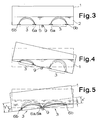
- the measuring electrodes 6 of the measuring sensors 3 are arranged flat on the bottom 5 of the container 1 and that the measuring sensors 3 are each designed as a stray field sensor with a stray field extending in the liquid 2 towards the liquid level. This can be seen particularly clearly in FIG. 3.
- the tilting axis 9 does not have to be physically present, it is always virtually present in the system, even if the container 1 in FIG. 4 is shifted parallel to itself, for example. It is essential that in principle a measuring sensor 3 is arranged on both sides of the "center". It can be seen from FIG. 3 that when the container 1 is level, the liquid level in the container 1 in the area of both measuring sensors 3 is at the same distance from the bottom 5, so that the stray fields measured are identical within the scope of the measuring and evaluation accuracy.
- FIG. 3 shows that when the container 1 is level, the liquid level in the container 1 in the area of both measuring sensors 3 is at the same distance from the bottom 5, so that the stray fields measured are identical within the scope of the measuring and evaluation accuracy.
- FIG. 5 makes it clear that in the case of the inclination measurement explained with reference to FIGS. 3 and 4, it is more favorable with regard to the evaluation if the normal level of the liquid 2 in the container 1 is as low as possible. It can be seen that the relative change x / y in FIG. 5 is considerably greater than the relative change x '/ y'. Thus, the farther the outer measuring electrodes 6b are from the measuring electrodes 6a in the middle and the lower the filling height, the higher the sensitivity, although the available angular measuring range is of course correspondingly smaller.
- An electrical measuring arrangement of the type explained above can be used in a self-contained manner as a measuring arrangement for other mechanical data.
- the container together with the liquid contained therein can itself form part of the measuring arrangement, so that other mechanical data, for example the inclination of the container with the liquid therein, a rotation of the container, a linear acceleration of the container and other mechanical data can be measured by measuring the behavior of the liquid in the container.
- the next step is the configuration according to FIG. 5, which is characterized in that the measuring electrodes 6a of the two measuring sensors 3 which are close to the tilt axis 9 are combined in a single electrode surface.
- This is, of course, a considerable simplification in terms of the circuit structure, it only being necessary to ensure that the electrode surface of the electrode forming the two measuring electrodes 6a is centered on the tilt axis 9, even if it is only virtually present.
- the measuring arrangements according to FIGS. 3 to 5 are only sensitive with respect to an inclination or tilting about the tilt axis 9, they are not sensitive to tilt or only very slightly sensitive to a tilt axis running perpendicular thereto. If you want to be able to measure inclinations about mutually perpendicular tilting axes, i.e. ultimately inclinations in all directions, it is recommended that in addition to the first pair of measuring sensors 3 a second pair of measuring sensors 3 is provided and angularly offset, preferably by 90 °, relative to the the first pair of measuring sensors 3 is arranged centered on the same center as the first pair of measuring sensors 3.
- FIG. 6 shows such a measuring arrangement with two pairs of measuring sensors 3, in which case it also applies that the measuring electrodes 6a of all measuring sensors 3 close to the center are combined in a single electrode surface.
- the angles indicated by the arc-shaped arrows are in each case 90 °.
- Fig. 7 shows the measuring arrangement from Fig. 6 with the schematically indicated substrate 10 with the applied measuring electrodes 6a, 6b, which have been produced in planar technology, with a generator 11, a first subtraction circuit 12 for the first pair of measuring sensors 3, a second Subtraction circuit 13 for the second pair of measuring sensors 3, a zero position detection stage 14 and an AND circuit 15.
- the inclination measurement signals for the x direction are at the top and for the y direction at the bottom.
- a signal is only output at the middle output when the container 1 is exactly in a horizontal orientation, that is to say there is no inclination in any direction. This is one way of carrying out the corresponding evaluation using the evaluation circuit 4.
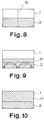
- Fig. 8 shows a further preferred embodiment in mechanical terms, which is characterized in that at least one separating element 16 is arranged or formed in the container 1, that through the separating element a certain, increased flow resistance for the liquid when flowing from one side of the separating element 16 to the other side of the separating element 16 and that a certain damping can be predetermined.
- the damping constant of the container 1 used here as the inclination sensor can be determined by the number and size of the openings in the isolating switch 16, which is designed here as a perforated plate.
- An alternative could also be to design the separating element 16 as a dividing wall with openings or as a double dividing wall with an underflow channel, that is to say to divide the container 1 into two parts with a flow connection of small cross-section.
- an acoustic evaluation signal can be triggered by the evaluation circuit 4, in particular that different evaluation signals can be triggered depending on the sign of the output signal indicating the direction of tilt.
- the stray field sensors of the type in question can be operated at temperatures up to approx. 600 K, at least if they are implemented in planar technology. Of course, you have to choose the right materials. For the rest, as has been explained at the beginning, one can use a purely conductivity sensor for calibration or standardization purposes Provide the stray field sensor used, but this is shown in detail in the figures.
- the evaluation circuit 4 is designed as evaluation electronics and, in particular, has a microprocessor or is integrated in a microprocessor.
- FIG. 10 shows a preferred or at least sometimes preferred form, in which the container 1 with the Liquid 2 and the auxiliary liquid 17 is completely filled. This sometimes has less of an impact.
- Fig. 11 now shows an application for a measuring arrangement according to the invention such that the container 1 in connection with a deformation in particular its inclination-changing deformation body 18 is inserted by the action of weight.
- the deformation body 18 is a bending rod, which can be used, for example, in a balance to hold a weight to be weighed.
- the angle of inclination is proportional to the force introduced into the deformation bodies 18, for example weight.
- the measuring arrangement used here according to the invention as an inclination sensor can have a very high sensitivity (for example 1 mV / 0.001 °).
- a very high sensitivity for example 1 mV / 0.001 °.
- the measuring arrangement to be used as an inclination sensor can also be used in conjunction with a deformation body 18 for deformation measurements as such, for example for measuring positional deviations in workpieces, buildings or bridges.
- a deformation body 18 for deformation measurements as such, for example for measuring positional deviations in workpieces, buildings or bridges.
- the detection of the inclination of the liquid level in the container 1 can be used in many other fields of application, for example for linear acceleration measurement, in the context of a rotation measurement in which the liquid level changes due to radial acceleration, correspondingly also for speed measurement etc.
- the miniaturization by the flat arrangement of the Measuring electrodes 6 of the measuring sensors 3 on the bottom 5 of the container 1, in particular in the context of planar technology on a substrate 10, are of very particular advantage.
Landscapes
- Physics & Mathematics (AREA)
- General Physics & Mathematics (AREA)
- Engineering & Computer Science (AREA)
- Radar, Positioning & Navigation (AREA)
- Remote Sensing (AREA)
- Thermal Sciences (AREA)
- Fluid Mechanics (AREA)
- Measurement Of Levels Of Liquids Or Fluent Solid Materials (AREA)
- Investigating Or Analyzing Materials By The Use Of Electric Means (AREA)
- Level Indicators Using A Float (AREA)
Claims (21)
- Dispositif de mesure électrique pour la mesure conductométrique du niveau, ou de données mécaniques qui en dérivent, d'un liquide (2) électriquement conducteur se trouvant dans un récipient (1) de préférence fermé, qui présente des propriétés électriques fixes, comprenant au moins deux détecteurs de mesure (3) munis respectivement de deux électrodes de mesure (6a, 6b) en contact avec le liquide (2), qui sont disposées avec un écart latéral mutuel déterminé, dans lequel le récipient (1) peut basculer autour d'un axe de basculement (9) se trouvant en tout cas virtuellement au milieu du fond (5), dans lequel, de part et d'autre de l'axe de basculement (9) est disposé respectivement un détecteur de mesure (3), et dans lequel les valeurs de mesure des deux détecteurs de mesure (3) peuvent être évaluées dans un circuit de détection décision (4), caractérisé en ce que les électrodes de mesure (6) des détecteurs de mesure (3) sont disposées en nappe au fond (5) du récipient (1) et les détecteurs de mesure (3) sont réalisés respectivement sous forme de détecteurs à zones de dispersion munis d'une zone de dispersion s'étendant dans le liquide (2) en direction de la surface du liquide.
- Dispositif de mesure selon la revendication 1, caractérisé en ce que le récipient (1), y compris le liquide (2) qui s'y trouve, fait lui-même partie du dispositif de mesure.
- Dispositif de mesure selon la revendication 1 ou 2, caractérisé en ce que les électrodes de mesure (6a, 6b) des détecteurs de mesure (3) se trouvent essentiellement dans un seul plan.
- Dispositif de mesure selon l'une quelconque des revendications 1 à 3, caractérisé en ce que, en dehors des détecteurs de mesure (3) au fond (5) du récipient (1), sont disposés des détecteurs de mesure (3) du même type contre au moins une paroi du récipient (1).
- Dispositif de mesure selon l'une quelconque des revendications 1 à 4, caractérisé en ce que les électrodes de mesure (6) sont disposées à proximité des bords externes du fond (5).
- Dispositif de mesure selon l'une quelconque des revendications 1 à 4, caractérisé en ce que la première électrode de mesure (6a) forme une surface d'électrode de forme circulaire essentiellement fermée et l'autre électrode de mesure (6b) forme une surface d'électrode circulaire disposée au centre du cercle.
- Dispositif de mesure selon l'une quelconque des revendications 1 à 6, caractérisé en ce que les électrodes de mesure (6) sont réalisées (respectivement) dans une technique planaire sur un substrat (10).
- Dispositif de mesure selon l'une quelconque des revendications 1 à 7, caractérisé en ce que les électrodes de mesure (6a) des deux détecteurs de mesure (3) proches de l'axe de basculement (9) se trouvent au même potentiel.
- Dispositif de mesure selon la revendication 8, caractérisé en ce que les électrodes de mesure (6a) des deux détecteurs de mesure (3), proches de l'axe de basculement (9) sont rassemblées dans une seule surface d'électrode.
- Dispositif de mesure selon l'une quelconque des revendications 1 à 9, caractérisé en ce que, en plus de la première paire de détecteurs de mesure (3) au fond (5), on prévoit une seconde paire de détecteurs de mesure (3) au fond (5), qui est disposée en formant un angle de préférence de 90°, en étant décalée par rapport à la première paire de détecteurs de mesure (3) au fond (5) et en étant centrée sur le même centre que celui de la première paire de détecteurs de mesure (3) au fond (5).
- Dispositif de mesure selon la revendication 10, caractérisé en ce que les électrodes de mesure (6a) de tous les détecteurs de mesure (3), proches du centre, sont rassemblées en une seule surface d'électrodes.
- Dispositif de mesure selon l'une quelconque des revendications 1 à 11, caractérisé en ce que, dans le récipient (1), est disposé ou réalisé au moins un élément de séparation (16), en ce que, à l'intervention de l'élément de séparation (16), une résistance à l'écoulement supérieure, déterminée est procurée pour le liquide lorsqu'il s'écoule depuis un côté de l'élément de séparation (16), et en ce qu'ainsi, un amortissement déterminé peut être prédéfini.
- Dispositif de mesure selon la revendication 12, caractérisé en ce que l'élément de séparation (16) est réalisé en forme de tôle perforée, en forme de paroi de séparation munie d'ouvertures ou en forme de double paroi de séparation à canal d'écoulement inférieur.
- Dispositif de mesure selon l'une quelconque des revendications 1 à 13, caractérisé en ce que, à partir du circuit de détection décision (4), chaque fois en fonction du signe de polarité du signal de départ indiquant la direction de basculement, différents signaux acoustiques d'évaluation peuvent être déclenchés.
- Dispositif de mesure selon l'une quelconque des revendications 1 à 14, caractérisé en ce que, aux détecteurs de mesure (3) est attribué un détecteur de mesure (3) réalisé en forme de détecteur de la conductivité, en particulier également en forme de détecteur à zone de dispersion, à des fins de calibrage.
- Dispositif de mesure selon l'une quelconque des revendications 1 à 15, caractérisé en ce que le circuit de détection décision (4) est réalisé en forme d'électronique d'évaluation et présente un microprocesseur ou bien est intégré dans un microprocesseur.
- Dispositif de mesure selon l'une quelconque des revendications 1 à 16, caractérisé en ce que le récipient (1) est rempli, au-dessus du liquide (2) électriquement conducteur, à l'aide d'un liquide auxiliaire (17) non électriquement conducteur à poids volumique inférieur.
- Dispositif de mesure selon la revendication 17, caractérisé en ce que le récipient (1) est rempli complètement avec le liquide (2) et le liquide auxiliaire (17).
- Dispositif de mesure selon l'une quelconque des revendications 1 à 17, caractérisé en ce que en ce qu'on fait le vide dans le récipient (1) au-dessus du liquide (2) respectivement du liquide auxiliaire (17).
- Dispositif de mesure selon l'une quelconque des revendications 1 à 19, caractérisé en ce que le circuit de détection décision (4) est réalisé pour l'enregistrement d'un profil de hauteur de remplissage.
- Utilisation d'un dispositif de mesure électrique selon l'une quelconque des revendications 1 à 20 pour la mesure de l'inclinaison.
Applications Claiming Priority (8)
| Application Number | Priority Date | Filing Date | Title |
|---|---|---|---|
| DE4007232 | 1990-03-07 | ||
| DE4007232 | 1990-03-07 | ||
| DE4028730 | 1990-09-10 | ||
| DE4028730 | 1990-09-10 | ||
| DE4031845 | 1990-10-08 | ||
| DE4031845 | 1990-10-08 | ||
| DE19904036262 DE4036262A1 (de) | 1990-03-07 | 1990-11-14 | Elektrische messanordnung zur messung bzw. berechnung des fuellstandes oder anderer mechanischer daten einer elektrisch leitenden fluessigkeit |
| DE4036262 | 1990-11-14 |
Publications (3)
| Publication Number | Publication Date |
|---|---|
| EP0447810A2 EP0447810A2 (fr) | 1991-09-25 |
| EP0447810A3 EP0447810A3 (en) | 1992-01-08 |
| EP0447810B1 true EP0447810B1 (fr) | 1994-12-14 |
Family
ID=27434901
Family Applications (1)
| Application Number | Title | Priority Date | Filing Date |
|---|---|---|---|
| EP91102305A Expired - Lifetime EP0447810B1 (fr) | 1990-03-07 | 1991-02-19 | Dispositif de mesure de niveau ou autre propriété mécanique d'un liquide conducteur |
Country Status (5)
| Country | Link |
|---|---|
| US (1) | US5182947A (fr) |
| EP (1) | EP0447810B1 (fr) |
| AT (1) | ATE115717T1 (fr) |
| DE (1) | DE59103838D1 (fr) |
| ES (1) | ES2067064T3 (fr) |
Families Citing this family (18)
| Publication number | Priority date | Publication date | Assignee | Title |
|---|---|---|---|---|
| JP3471881B2 (ja) * | 1993-02-01 | 2003-12-02 | リー/マータク・エンジニアリング・インコーポレイテッド | 変動する流体位及び傾斜検知プローブ装置 |
| GB9311187D0 (en) * | 1993-05-29 | 1993-07-14 | Schlumberger Ind Ltd | Fluid level sensing systems |
| US6058934A (en) * | 1995-11-02 | 2000-05-09 | Chiron Diagnostics Corporation | Planar hematocrit sensor incorporating a seven-electrode conductivity measurement cell |
| US5765434A (en) * | 1996-07-18 | 1998-06-16 | Scepter Scientific, Inc. | Capacitive water height gauge and method |
| GB2323671B (en) * | 1997-03-27 | 2001-03-14 | Eastman Kodak Co | Vessel contents sensor |
| WO1999010714A1 (fr) * | 1997-08-25 | 1999-03-04 | Millennium Sensors Ltd. | Detecteur de niveau de liquide a effet capacitif compense |
| US6539286B1 (en) | 1998-01-26 | 2003-03-25 | Micron Technology, Inc. | Fluid level sensor |
| NL1012197C2 (nl) | 1999-05-31 | 2000-12-01 | Univ Delft Tech | Inrichting voor het bepalen van een hoeveelheid van een vloeistof. |
| KR100912157B1 (ko) * | 2001-07-18 | 2009-08-14 | 텔-아비브 유니버시티 퓨처 테크놀로지 디벨롭먼트 엘.피. | 프로톤 전도막을 구비하고 물과 연료에 대한 처리를 개선한 연료 전지 |
| US6605947B2 (en) * | 2001-10-03 | 2003-08-12 | Yi-Chia Liao | Cup shape sensible container for detecting liquid property |
| US6684138B1 (en) * | 2002-05-31 | 2004-01-27 | Hwh Corporation | Dynamic platform leveling system |
| JP4742683B2 (ja) * | 2005-06-02 | 2011-08-10 | ソニー株式会社 | 液体検知装置及び液体吐出装置 |
| WO2009029533A1 (fr) | 2007-08-24 | 2009-03-05 | Zevex, Inc. | Détecteur ultrasonore d'air et de fluide |
| US8303613B2 (en) * | 2007-12-07 | 2012-11-06 | Zevex, Inc. | Ultrasonic instrument using langevin type transducers to create transverse motion |
| DE102009030658B4 (de) * | 2009-06-25 | 2011-09-01 | Carl Freudenberg Kg | Wischgerät |
| US9300409B1 (en) * | 2011-08-01 | 2016-03-29 | eentec, LLC | Rotational electrochemical seismometer using magnetohydrodynamic technology and related methods |
| US8549764B2 (en) * | 2011-09-23 | 2013-10-08 | Lexmark International, Inc. | Fluid tilt sensor within ink tank supply item for micro-fluid applications |
| DE102023127823A1 (de) * | 2023-10-11 | 2025-04-17 | Endress+Hauser SE+Co. KG | Vorrichtung zur Bestimmung eines Messwerts einer Leitfähigkeit |
Citations (2)
| Publication number | Priority date | Publication date | Assignee | Title |
|---|---|---|---|---|
| DE2551798A1 (de) * | 1974-11-18 | 1976-05-26 | Sperry Rand Corp | Elektrischer neigungsmessfuehler |
| DE3411252A1 (de) * | 1984-03-27 | 1985-10-10 | Bayerische Motoren Werke AG, 8000 München | Neigungssensor |
Family Cites Families (31)
| Publication number | Priority date | Publication date | Assignee | Title |
|---|---|---|---|---|
| GB993715A (en) * | 1961-12-11 | 1965-06-02 | English Electric Co Ltd | Improvements in or relating to tilt-sensitive devices |
| DE1250146B (de) * | 1963-11-02 | 1967-09-14 | Norddeutsche Mende Rundfunk K G | Vorrichtung zur mengen- oder standmessung von flüssigem, gasförmigem oder festen gut |
| DE1296811B (de) * | 1965-05-05 | 1969-06-04 | Holzer Walter | Metallischer Fluessigkeitsbehaelter |
| US3515987A (en) * | 1967-10-20 | 1970-06-02 | Avco Corp | Coplanar dielectric probe having means for minimizing capacitance from stray sources |
| DE1780523A1 (de) * | 1968-09-25 | 1971-08-26 | Wolfgang Mueller | Einrichtung zur UEberwachung der in einem Bremskreis von hydraulischen Kraftfahrzeugbremsen minimal zulaessigen Bremsfluessigkeitsmenge |
| US3671857A (en) * | 1970-04-29 | 1972-06-20 | Karlis Alfredovich Bergmanis | Device for measuring permittivity of materials |
| US3781672A (en) * | 1971-05-10 | 1973-12-25 | Drexelbrook Controls | Continuous condition measuring system |
| SU459680A1 (ru) * | 1972-02-22 | 1975-02-05 | Киргизский Научно-Исследовательский Институт Водного Хозяйства | Сигнализатор уровн |
| AT348267B (de) * | 1973-12-20 | 1979-02-12 | Contraves Ag | Fuehlelement zur bestimmung der abweichung vom lot |
| US3986110A (en) * | 1975-08-29 | 1976-10-12 | Surface Systems, Inc. | Water depth measuring device |
| US4135151A (en) * | 1977-12-14 | 1979-01-16 | Surface Systems, Inc. | Apparatus for detecting wet and icy surface conditions |
| US4851831A (en) * | 1981-05-13 | 1989-07-25 | Drexelbrook Engineering Co. | Two-wire level measuring instrument |
| SU976300A1 (ru) * | 1981-07-27 | 1982-11-23 | Государственный научно-исследовательский институт теплоэнергетического приборостроения "НИИтеплоприбор" | Преобразователь дискретного уровнемера сыпучих материалов |
| US4568874A (en) * | 1983-02-17 | 1986-02-04 | Drexelbrook Controls, Inc. | RF Admittance apparatus and method for monitoring the contents of a pipe |
| DE3308361A1 (de) * | 1983-03-09 | 1984-09-13 | WTW Wissenschaftlich-technische Werkstätten GmbH, 8120 Weilheim | Messzelle zur erfassung der elektrolytischen leitfaehigkeit von milch |
| US4503622A (en) * | 1983-04-20 | 1985-03-12 | Sperry Corporation | Precision inclinometer with digital numerical readout |
| US4547972A (en) * | 1983-08-30 | 1985-10-22 | Sperry Corporation | Tilt sensor and monitoring system |
| US4531300A (en) * | 1984-05-07 | 1985-07-30 | Sperry Corporation | Electronic inclination gauge with acceleration compensation |
| DD226068A1 (de) * | 1984-05-28 | 1985-08-14 | Suhl Feinmesszeugfab Veb | Kapazitives neigungs- und ebenheitsmessgeraet |
| NL8402241A (nl) * | 1984-07-16 | 1986-02-17 | Philips Nv | Inrichting voor het bepalen van de momentane scheefstand van een bewegend voorwerp. |
| DE3617234A1 (de) * | 1986-05-22 | 1987-11-26 | Meyer Fa Rud Otto | Wasser- oder feuchtemelder |
| US4845421A (en) * | 1986-10-10 | 1989-07-04 | Mineral Control Instrumentation Ltd. | Method and apparatus for measuring the moisture content of a substance |
| US4779353A (en) * | 1987-03-26 | 1988-10-25 | Schlumberger Technology Corporation | Tool for measuring inclination and rotation |
| DE3838660A1 (de) * | 1987-06-30 | 1989-04-27 | Walter Nicolai | Verfahren zur messung und ueberwachung des volumens der verdraengungsfluessigkeit in der verdraengungskammer einer volumenaenderungseinrichtung unter beruecksichtigung zulaessiger winkel-abweichungen der grundflaechenebene (standflaeche) der verdraengungskammer von der horizontalen |
| IT1211347B (it) * | 1987-07-31 | 1989-10-18 | Fiat Auto Spa | Dispositivo di misura del quantitativo di liquido contenuto all interno di un serbatoio |
| DE3725752A1 (de) * | 1987-08-04 | 1989-03-02 | Vdo Schindling | Verfahren und vorrichtung zur anzeige des fluessigkeitsniveaus in einem kraftfahrzeugtank |
| JPH01126535A (ja) * | 1987-11-12 | 1989-05-18 | Kao Corp | 皮膚水分含有量の測定方法および装置 |
| EP0358788A1 (fr) * | 1988-09-13 | 1990-03-21 | G. + G. Technics Ag | Capteur d'inclinaison électrolytique |
| JPH02150726A (ja) * | 1988-12-01 | 1990-06-11 | Matsushita Electric Ind Co Ltd | 液量検出装置 |
| DE3920246A1 (de) * | 1989-06-21 | 1991-01-03 | Seidel Hans Hermann | Fluessigkeitsneigungssensor mit elektrischem ausgangssignal |
| US4994750A (en) * | 1989-07-14 | 1991-02-19 | Ohio Mattress Company Licensing & Components | Use of capacitance for protecting against overheating of a waterbed heater |
-
1991
- 1991-02-19 DE DE59103838T patent/DE59103838D1/de not_active Expired - Lifetime
- 1991-02-19 AT AT91102305T patent/ATE115717T1/de not_active IP Right Cessation
- 1991-02-19 ES ES91102305T patent/ES2067064T3/es not_active Expired - Lifetime
- 1991-02-19 EP EP91102305A patent/EP0447810B1/fr not_active Expired - Lifetime
- 1991-03-06 US US07/664,982 patent/US5182947A/en not_active Expired - Lifetime
Patent Citations (2)
| Publication number | Priority date | Publication date | Assignee | Title |
|---|---|---|---|---|
| DE2551798A1 (de) * | 1974-11-18 | 1976-05-26 | Sperry Rand Corp | Elektrischer neigungsmessfuehler |
| DE3411252A1 (de) * | 1984-03-27 | 1985-10-10 | Bayerische Motoren Werke AG, 8000 München | Neigungssensor |
Also Published As
| Publication number | Publication date |
|---|---|
| EP0447810A2 (fr) | 1991-09-25 |
| US5182947A (en) | 1993-02-02 |
| ATE115717T1 (de) | 1994-12-15 |
| ES2067064T3 (es) | 1995-03-16 |
| EP0447810A3 (en) | 1992-01-08 |
| DE59103838D1 (de) | 1995-01-26 |
Similar Documents
| Publication | Publication Date | Title |
|---|---|---|
| EP0447810B1 (fr) | Dispositif de mesure de niveau ou autre propriété mécanique d'un liquide conducteur | |
| DE3545630C2 (fr) | ||
| DE69206770T2 (de) | Dreiachsiger Beschleunigungsmesser | |
| EP2106551B1 (fr) | Capteur d'accélération micromécanique à plusieurs axes | |
| CH673897A5 (fr) | ||
| CH660522A5 (de) | Elektronische nivelliervorrichtung. | |
| DE3781472T2 (de) | Beschleunigungsmesser. | |
| DE4102805A1 (de) | Kapazitiver beschleunigungssensor | |
| DD226068A1 (de) | Kapazitives neigungs- und ebenheitsmessgeraet | |
| DE4329571A1 (de) | Neigungssensor | |
| DE10060091B4 (de) | Mikromechanischer Inertialsensor | |
| DE3744411C2 (fr) | ||
| DE19717580C2 (de) | Neigungssensor | |
| DE60221103T2 (de) | Aus Halbleitermaterial hergestellter integrierter Kreisel mit wenigstens einer empfindlichen Achse in der Sensorebene | |
| EP1127253A1 (fr) | Capteur de mesure capacitif et son procede d'utilisation | |
| DE4036262A1 (de) | Elektrische messanordnung zur messung bzw. berechnung des fuellstandes oder anderer mechanischer daten einer elektrisch leitenden fluessigkeit | |
| EP0221016B1 (fr) | Inclinomètre | |
| DE3912444A1 (de) | Neigungswinkelmessgeraet | |
| DE4305934B4 (de) | Anordnung von Sensoren zur Messung der Luftfeuchte | |
| DE102008025236B4 (de) | Kapazitiver Sensor und ein Verfahren zur Herstellung eines kapazitiven Sensors | |
| DE102005025908B3 (de) | Kapazitiver Sensor zum Messen einer Messgrösse | |
| EP1145025B1 (fr) | Detecteur de champ magnetique capacitif | |
| DE10217859C1 (de) | Neigungsvorrichtung mit einem Pendel | |
| DE102004046411B4 (de) | Beschleunigungssensor | |
| AT398845B (de) | Gerät zum messen und/oder prüfen von neigungen |
Legal Events
| Date | Code | Title | Description |
|---|---|---|---|
| PUAI | Public reference made under article 153(3) epc to a published international application that has entered the european phase |
Free format text: ORIGINAL CODE: 0009012 |
|
| AK | Designated contracting states |
Kind code of ref document: A2 Designated state(s): AT BE CH DE DK ES FR GB GR IT LI LU NL SE |
|
| PUAL | Search report despatched |
Free format text: ORIGINAL CODE: 0009013 |
|
| 17P | Request for examination filed |
Effective date: 19911029 |
|
| AK | Designated contracting states |
Kind code of ref document: A3 Designated state(s): AT BE CH DE DK ES FR GB GR IT LI LU NL SE |
|
| 17Q | First examination report despatched |
Effective date: 19930505 |
|
| GRAA | (expected) grant |
Free format text: ORIGINAL CODE: 0009210 |
|
| AK | Designated contracting states |
Kind code of ref document: B1 Designated state(s): AT BE CH DE DK ES FR GB GR IT LI LU NL SE |
|
| PG25 | Lapsed in a contracting state [announced via postgrant information from national office to epo] |
Ref country code: GR Free format text: LAPSE BECAUSE OF FAILURE TO SUBMIT A TRANSLATION OF THE DESCRIPTION OR TO PAY THE FEE WITHIN THE PRESCRIBED TIME-LIMIT Effective date: 19941214 Ref country code: DK Effective date: 19941214 |
|
| REF | Corresponds to: |
Ref document number: 115717 Country of ref document: AT Date of ref document: 19941215 Kind code of ref document: T |
|
| REF | Corresponds to: |
Ref document number: 59103838 Country of ref document: DE Date of ref document: 19950126 |
|
| EAL | Se: european patent in force in sweden |
Ref document number: 91102305.9 |
|
| PGFP | Annual fee paid to national office [announced via postgrant information from national office to epo] |
Ref country code: SE Payment date: 19950203 Year of fee payment: 5 |
|
| ITF | It: translation for a ep patent filed | ||
| ET | Fr: translation filed | ||
| PG25 | Lapsed in a contracting state [announced via postgrant information from national office to epo] |
Ref country code: LU Free format text: LAPSE BECAUSE OF NON-PAYMENT OF DUE FEES Effective date: 19950228 |
|
| GBT | Gb: translation of ep patent filed (gb section 77(6)(a)/1977) |
Effective date: 19950214 |
|
| REG | Reference to a national code |
Ref country code: ES Ref legal event code: FG2A Ref document number: 2067064 Country of ref document: ES Kind code of ref document: T3 |
|
| PLBE | No opposition filed within time limit |
Free format text: ORIGINAL CODE: 0009261 |
|
| STAA | Information on the status of an ep patent application or granted ep patent |
Free format text: STATUS: NO OPPOSITION FILED WITHIN TIME LIMIT |
|
| 26N | No opposition filed | ||
| PG25 | Lapsed in a contracting state [announced via postgrant information from national office to epo] |
Ref country code: SE Effective date: 19960220 |
|
| PGFP | Annual fee paid to national office [announced via postgrant information from national office to epo] |
Ref country code: FR Payment date: 19960222 Year of fee payment: 6 |
|
| PG25 | Lapsed in a contracting state [announced via postgrant information from national office to epo] |
Ref country code: FR Effective date: 19971030 |
|
| REG | Reference to a national code |
Ref country code: FR Ref legal event code: ST |
|
| REG | Reference to a national code |
Ref country code: FR Ref legal event code: RN |
|
| REG | Reference to a national code |
Ref country code: FR Ref legal event code: IC |
|
| REG | Reference to a national code |
Ref country code: GB Ref legal event code: IF02 |
|
| PG25 | Lapsed in a contracting state [announced via postgrant information from national office to epo] |
Ref country code: IT Free format text: LAPSE BECAUSE OF NON-PAYMENT OF DUE FEES;WARNING: LAPSES OF ITALIAN PATENTS WITH EFFECTIVE DATE BEFORE 2007 MAY HAVE OCCURRED AT ANY TIME BEFORE 2007. THE CORRECT EFFECTIVE DATE MAY BE DIFFERENT FROM THE ONE RECORDED. Effective date: 20050219 |
|
| PG25 | Lapsed in a contracting state [announced via postgrant information from national office to epo] |
Ref country code: GB Free format text: LAPSE BECAUSE OF NON-PAYMENT OF DUE FEES Effective date: 20060219 |
|
| GBPC | Gb: european patent ceased through non-payment of renewal fee |
Effective date: 20060219 |
|
| REG | Reference to a national code |
Ref country code: GB Ref legal event code: 728V |
|
| REG | Reference to a national code |
Ref country code: GB Ref legal event code: 728Y |
|
| PGFP | Annual fee paid to national office [announced via postgrant information from national office to epo] |
Ref country code: CH Payment date: 20080118 Year of fee payment: 18 Ref country code: ES Payment date: 20080307 Year of fee payment: 18 |
|
| PGFP | Annual fee paid to national office [announced via postgrant information from national office to epo] |
Ref country code: GB Payment date: 20080227 Year of fee payment: 18 Ref country code: NL Payment date: 20080229 Year of fee payment: 18 |
|
| PGFP | Annual fee paid to national office [announced via postgrant information from national office to epo] |
Ref country code: AT Payment date: 20080125 Year of fee payment: 18 |
|
| PGFP | Annual fee paid to national office [announced via postgrant information from national office to epo] |
Ref country code: BE Payment date: 20080307 Year of fee payment: 18 |
|
| BERE | Be: lapsed |
Owner name: *HL PLANARTECHNIK G.M.B.H. Effective date: 20090228 |
|
| REG | Reference to a national code |
Ref country code: CH Ref legal event code: PL |
|
| GBPC | Gb: european patent ceased through non-payment of renewal fee |
Effective date: 20090219 |
|
| PG25 | Lapsed in a contracting state [announced via postgrant information from national office to epo] |
Ref country code: CH Free format text: LAPSE BECAUSE OF NON-PAYMENT OF DUE FEES Effective date: 20090228 Ref country code: LI Free format text: LAPSE BECAUSE OF NON-PAYMENT OF DUE FEES Effective date: 20090228 Ref country code: AT Free format text: LAPSE BECAUSE OF NON-PAYMENT OF DUE FEES Effective date: 20090219 |
|
| NLV4 | Nl: lapsed or anulled due to non-payment of the annual fee |
Effective date: 20090901 |
|
| PG25 | Lapsed in a contracting state [announced via postgrant information from national office to epo] |
Ref country code: NL Free format text: LAPSE BECAUSE OF NON-PAYMENT OF DUE FEES Effective date: 20090901 |
|
| PG25 | Lapsed in a contracting state [announced via postgrant information from national office to epo] |
Ref country code: BE Free format text: LAPSE BECAUSE OF NON-PAYMENT OF DUE FEES Effective date: 20090228 |
|
| REG | Reference to a national code |
Ref country code: ES Ref legal event code: FD2A Effective date: 20090220 |
|
| PG25 | Lapsed in a contracting state [announced via postgrant information from national office to epo] |
Ref country code: GB Free format text: LAPSE BECAUSE OF NON-PAYMENT OF DUE FEES Effective date: 20090219 |
|
| PGFP | Annual fee paid to national office [announced via postgrant information from national office to epo] |
Ref country code: IT Payment date: 20080326 Year of fee payment: 18 |
|
| PGRI | Patent reinstated in contracting state [announced from national office to epo] |
Ref country code: IT Effective date: 20091201 |
|
| PGFP | Annual fee paid to national office [announced via postgrant information from national office to epo] |
Ref country code: DE Payment date: 20091125 Year of fee payment: 20 |
|
| PG25 | Lapsed in a contracting state [announced via postgrant information from national office to epo] |
Ref country code: ES Free format text: LAPSE BECAUSE OF NON-PAYMENT OF DUE FEES Effective date: 20090220 |
|
| REG | Reference to a national code |
Ref country code: DE Ref legal event code: R071 Ref document number: 59103838 Country of ref document: DE |
|
| PGRI | Patent reinstated in contracting state [announced from national office to epo] |
Ref country code: IT Effective date: 20091201 |
|
| PG25 | Lapsed in a contracting state [announced via postgrant information from national office to epo] |
Ref country code: DE Free format text: LAPSE BECAUSE OF EXPIRATION OF PROTECTION Effective date: 20110219 |