EP0447854B1 - Dispositif de coupe pour destructeur de documents - Google Patents
Dispositif de coupe pour destructeur de documents Download PDFInfo
- Publication number
- EP0447854B1 EP0447854B1 EP91102991A EP91102991A EP0447854B1 EP 0447854 B1 EP0447854 B1 EP 0447854B1 EP 91102991 A EP91102991 A EP 91102991A EP 91102991 A EP91102991 A EP 91102991A EP 0447854 B1 EP0447854 B1 EP 0447854B1
- Authority
- EP
- European Patent Office
- Prior art keywords
- cutting
- spacing
- mechanism according
- roller surface
- axial
- Prior art date
- Legal status (The legal status is an assumption and is not a legal conclusion. Google has not performed a legal analysis and makes no representation as to the accuracy of the status listed.)
- Expired - Lifetime
Links
- 238000005520 cutting process Methods 0.000 title claims description 136
- 230000007246 mechanism Effects 0.000 claims description 13
- 239000000463 material Substances 0.000 claims description 9
- 230000007704 transition Effects 0.000 claims description 5
- 238000013461 design Methods 0.000 description 3
- 230000002349 favourable effect Effects 0.000 description 3
- 230000008901 benefit Effects 0.000 description 2
- 238000013459 approach Methods 0.000 description 1
- 230000015572 biosynthetic process Effects 0.000 description 1
- 230000008859 change Effects 0.000 description 1
- 238000010276 construction Methods 0.000 description 1
- 238000011161 development Methods 0.000 description 1
- 230000018109 developmental process Effects 0.000 description 1
- 238000005265 energy consumption Methods 0.000 description 1
- 238000003780 insertion Methods 0.000 description 1
- 230000037431 insertion Effects 0.000 description 1
- 238000004519 manufacturing process Methods 0.000 description 1
- 239000002245 particle Substances 0.000 description 1
- 239000002985 plastic film Substances 0.000 description 1
- 230000001360 synchronised effect Effects 0.000 description 1
- 229920001169 thermoplastic Polymers 0.000 description 1
- 230000036346 tooth eruption Effects 0.000 description 1
Images
Classifications
-
- B—PERFORMING OPERATIONS; TRANSPORTING
- B02—CRUSHING, PULVERISING, OR DISINTEGRATING; PREPARATORY TREATMENT OF GRAIN FOR MILLING
- B02C—CRUSHING, PULVERISING, OR DISINTEGRATING IN GENERAL; MILLING GRAIN
- B02C18/00—Disintegrating by knives or other cutting or tearing members which chop material into fragments
- B02C18/06—Disintegrating by knives or other cutting or tearing members which chop material into fragments with rotating knives
- B02C18/16—Details
- B02C18/18—Knives; Mountings thereof
- B02C18/182—Disc-shaped knives
-
- B—PERFORMING OPERATIONS; TRANSPORTING
- B02—CRUSHING, PULVERISING, OR DISINTEGRATING; PREPARATORY TREATMENT OF GRAIN FOR MILLING
- B02C—CRUSHING, PULVERISING, OR DISINTEGRATING IN GENERAL; MILLING GRAIN
- B02C18/00—Disintegrating by knives or other cutting or tearing members which chop material into fragments
- B02C18/0007—Disintegrating by knives or other cutting or tearing members which chop material into fragments specially adapted for disintegrating documents
-
- Y—GENERAL TAGGING OF NEW TECHNOLOGICAL DEVELOPMENTS; GENERAL TAGGING OF CROSS-SECTIONAL TECHNOLOGIES SPANNING OVER SEVERAL SECTIONS OF THE IPC; TECHNICAL SUBJECTS COVERED BY FORMER USPC CROSS-REFERENCE ART COLLECTIONS [XRACs] AND DIGESTS
- Y10—TECHNICAL SUBJECTS COVERED BY FORMER USPC
- Y10T—TECHNICAL SUBJECTS COVERED BY FORMER US CLASSIFICATION
- Y10T83/00—Cutting
- Y10T83/768—Rotatable disc tool pair or tool and carrier
- Y10T83/7809—Tool pair comprises rotatable tools
- Y10T83/783—Tool pair comprises contacting overlapped discs
Definitions
- the invention relates to a cutting device for a document shredder according to the preamble of claim 1.
- a document shredder is to be understood here as a device which is primarily intended to cut documents and other flat material, in particular paper, into strips which are as illegible as possible. It can also be used to cut other objects.
- a cutting device of the type mentioned has become known from DE-C-19 53 681. It creates a so-called torsion cut, ie it cuts the documents into narrow strips that are more or less strong Assume a screw shape because the two edges of the strip are deflected in different directions after the cut.
- the cutting unit according to DE-C-19 53 681 has the advantage that even when cutting layers of several papers in the passage which is formed between two pairs of cutting disks, there is sufficient space for the strip to be there can walk freely.
- a problem is the relatively large cutting disc height above the roller surface, because this makes the cutting discs sensitive to breakage and increases the roller diameter, the roller spacing and thus the amount of space and construction costs. Relatively sharp transition edges between the back of the cutting flank and the surface of the cutting roller disrupt the friction and adhesion-free passage of the strips. Strips are observed to stick to and be taken around the cutting disks, so strippers are usually required to prevent them from wrapping around the cutting rollers.
- DE-U-88 13 569 shows a similar design, in which the passage has a very elongated cross-sectional shape.
- the transitions between the back flanks of the cutting disks and the roller surface have small fillets, but they do not change the problem described above.
- the object of the invention is to improve a cutting unit of the type mentioned in such a way that with good cutting results and as little energy expenditure as possible and low risk of breakage, a strip pass is possible without the tendency for the strips to get caught on the rollers.
- the defined, squat trapezoidal shape of the passage allows the strip to take almost any position. Its tendency to form screws is reduced and also in the event that material is cut which tends to stretch when cutting, the corrugated cutting edges can pass through the passage unhindered.
- the compact trapezoidal shape can be further defined on the basis of various other criteria which are specified in the subclaims. However, due to the different designs, they are also to be understood as alternative, although a particularly advantageous embodiment can be used in combination, since they are not mutually exclusive. It is also important to define the generous rounding of the transitions between the cutting and back flanks each cutting disc and the roller surface. It has been found that this significantly reduces the tendency for the strips to jam, although this was not initially believed because it somewhat reduces the largest diagonal dimension in the passageway.
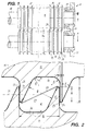
- FIG. 1 shows a cutting mechanism 11 with two cutting rollers 12, 13, each consisting of a roller body 16 with cutting disks 14, 15 formed integrally thereon.
- the roller bodies have on each side a journal 18 which is mounted in bearings 19 on a machine frame 20 of a document shredder which is not shown in further details.
- Fig. 1 it is indicated that the cutting rollers are axially supported against each other via a corresponding axially elastic bearing design of the bearing block 21 formed as a common bearing insert, so that they run against each other with as little friction as possible, but on the other hand also result in a good cutting profile and in the event of an overload can yield axially.
- the cutting disks 14, 15 are annular flange-like, preferably hardened structures projecting over the roller surface 17 of the continuous roller body 16, which have a cutting edge 22 running essentially in a radial plane and a back flank 23 running at an angle f with respect to this or a radial plane.
- the flanks 22, 23 are connected to one another by a cylindrical annular surface 24 forming the outer circumference of the cutting disk, which has a relatively small width s in the axial direction.
- the cutting disks are made in one piece with the roller body. However, they could also be lined up on a shaft in the form of individual disks, if this is cheaper for manufacturing reasons.
- the transition between the back flanks 23 and the cutting flanks 22 and the roller surface 17 is provided with generous fillets 45, namely with a radius r that is greater than one fifth of the cutting disc height h above the roller surface 17 (preferably, as in the exemplary embodiment, about a third of h ; see Fig. 2).
- the cutting flanks 22 of the cutting disks 14 of a cutting roller 12 rest against the corresponding cutting flanks 22 of the cutting disks 15 of the cutting roller 13, since these are in the same axial direction on both cutting rollers Distance b are arranged from each other.
- the cutting flanks 22 form a circumferential circular cutting edge 25 between them and the annular surface 24, which is determining for the distance dimension b .
- the cutting flank 22 runs essentially radially, but could also be designed differently if a low-friction engagement of the two cutting edge regions is ensured. For example, an even more generous fillet would be possible.
- This passage has a compact trapezoidal shape with corners rounded by the fillets 45, ie it approaches an equilateral trapezoid rather than an elongated strip-like one. This is achieved by the relatively steep course of the back flanks 23 together with a moderate cutting disc height h .
- the cutting rollers 12, 13 are arranged with an axial spacing A which is smaller than their outer diameter Da . This creates a lenticular overlap zone between the cutting disks, the largest dimension of which 2 has the dimension u in the connecting plane of the two cutting disc axes 30 shown in FIG. 2.
- the dimensions of the passage are also to be understood in this level, since it has its narrowest point in this level and widens in front of and behind it.
- the cutting disk height h can be approximately 2.5 mm with an axial cutting edge distance b of 4 mm.
- a center distance A of 23.5 mm there is an overlap u of 1.5 mm and thus a radial dimension d of the passage of 2.5 mm, while the dimension a , ie the smallest distance between the back flanks 23 in the passage 29 2, 6 mm.
- This small ring area also facilitates the cutting work by increasing the surface pressure in the cutting area.
- the relatively small width s of the annular surface 24 ensures that no pronounced corners are formed in the passage, which could give it a Z-shape.
- the dimension ratios apply, which are calculated from the previously specified data leave, also as particularly advantageous. Deviating from this, however, the values can differ.
- the flank angle can be selected between 20 and 35 ° without, on the one hand, increasing the risk of breakage too much or restricting the passage 29 too much.
- the favorable ratio between the outer diameter Da and the cutting disc distance b of approximately 6: 1 can be up to approximately 10: 1 and the width s of the ring surface 24 on the cutting disc circumference, which in the exemplary embodiment is approximately 8%, can be between 5% and 20% of the Cutting disc height and a sixth to a thirtieth, preferably a twentieth of the cutting edge distance b .
- a small ratio between the cutting disc height h (cantilever above the roller surface) is also advantageous and should be less than 70% of the cutting edge distance b .
- the radial dimension d of the passage should be smaller or approximately the same size as the axial cutting edge distance b . Based on the transverse distance a , ie the distance between the back flanks, these radial dimensions d should be less than five times and as small as possible twice as a .
- the overlap dimension u should be less than two thirds of this, based on the cutting disc height h , or less than half of these values, based on the axial cutting edge distance b or the radial dimension d of the passage.
- the function of the cutting unit is as follows: an input sheet or a sheet layer or a web or web layer (with continuous loading) runs, possibly guided by walls of an insertion slot, into the overlap area between the two cutting rollers, ie vertical in the drawing plane. It is gripped by the cutting rollers which run in opposite directions, ie in the same direction, whereby the ring surface 24, if this should be necessary for transport reasons, could be corrugated. It is thus pulled between the two rollers, and it is cut in the manner of a scissor cut even before the central plane containing the two axes 30 at the beginning of the lenticular overlap region by the cutting edges 25 of each pair of cutting disks interacting.
- the cut is made over the entire width at the same time, so that the material is held taut between the individual cut edges and is thus cut or torn like a cut even with somewhat blunt and not completely adjacent cutting edges. This is supported by the fact that after the cutting process, the ring surfaces 24, which adjoin the respective cutting line, move in opposite directions, so that the material would be separated because of the large stretching that would then occur.
- the resulting paper strip 28 lies in the passage 29, when it has reached the center plane of the two cutting rollers, obliquely with respect to its orientation (corresponding to the parting plane 35) assumed before the cutting process, as shown in FIG. 2, so that overall there is a slight helical rotation of the resulting strip results in what has led to the name "torsion cut” for this roller formation.
- this helical tendency to turn is relatively small in the cutting device according to the invention, ie the "pitch" of the resulting screw is very large.
- the strip 28 could also lie in a different position without getting stuck between the walls of the passage.
- the generous fillets 45 also contribute to this. Even a roughened or wavy edge cannot lead to a deadlock. Above all, regardless of its remaining screw shape, which depends on the material properties of the comminution material, the strip can lie in almost any rotational position without striking a passage wall.
- the cutting device according to the invention does not require a scraper. If one is provided, only in the case of particularly critical materials that tend to stick to the cutting rollers for other reasons.
- the compact shape of the passage could also be maintained or even further perfected if the passage, in contrast to its trapezoidal shape, was more adapted to a rectangular or, even better, circular or elongated hole shape.
- the roller surface 17 previously cylindrical between the cutting disks could be given a rounded shape 36, indicated by dash-dotted lines in FIG. 2, without correspondingly reducing the strength of the cutting disks.
- the strip could then move freely through the passage by more than 60 °.
- the generous fillets 45 would almost merge into a single complete round.
- a good rounding of the space forming the passage can also lead to the advantages of the invention, regardless of the relative dimensioning of this space.
Landscapes
- Engineering & Computer Science (AREA)
- Food Science & Technology (AREA)
- Crushing And Pulverization Processes (AREA)
Claims (12)
- Dispositif de coupe pour un destructeur de documents comprenant deux cylindres de coupe (12, 13), ceux-ci comportant des disques de coupe (14, 15) qui sont disposés à une distance (b) les uns des autres dans le sens axial, qui font saillie au-delà de la surface (17) des cylindres et qui présentent chacun un flanc de coupe (22), lequel s'étend radialement, pour l'essentiel, en se terminant par une arête de coupe périphérique (25), ainsi qu'un flanc arrière incliné (23), cependant que chaque arête de coupe (25) d'un disque de coupe (14) de l'un des cylindres de coupe (12) recouvre une arête de coupe dirigée en sens opposé (25) d'un disque de coupe (15) de l'autre cylindre de coupe (13) et coopère avec elle pour couper en bandes (28) un produit plat introduit entre les cylindres de coupe (12, 13), et cependant qu'un passage (29) destiné aux bandes (28) est formé entre les disques de coupe en étant délimité par les flancs de coupe et les flancs arrière (22, 23) de disques de coupe voisins (14, 15) et par la surface (17) des cylindres, caractérisé par le fait que le passage (29) présente une forme qui est ramassée d'une manière telle que la distance (a) entre les flancs arrière (23) à l'endroit le plus étroit du passage (29) soit supérieure à 40% environ de la dimension (d) du passage (29) dans le sens radial à l'endroit où il est le plus étroit, et par le fait que les transitions entre la surface (17) du cylindre et le flanc arrière (23) et/ou le flanc de coupe (22) sont pourvues d'arrondis (45) dont le rayon (r) est supérieur à un cinquième de la hauteur (h) des disques de coupe au-dessus de la surface du cylindre.
- Dispositif de coupe selon la revendication 1, caractérisé par le fait que la distance (a) entre les flancs arrière (23) à l'endroit le plus étroit du passage (29) est supérieure à 60% environ de la distance (b) dans le sens axial entre des arêtes de coupe voisines du même cylindre de coupe (12, 13).
- Dispositif de coupe selon la revendication 1 ou 2, caractérisé par le fait que la distance (a) entre les flancs arrière (23) à l'endroit le plus étroit du passage (29) est supérieure aux deux tiers environ de la hauteur des disques de coupe au-dessus de la surface (17) des cylindres.
- Dispositif de coupe selon l'une des revendications précédentes, caractérisé par le fait que la distance (a) entre les flancs arrière est égale à 75% environ de la dimension (d) dans le sens radial.
- Dispositif de coupe selon l'une des revendications précédentes, caractérisé par le fait que les cylindres de coupe (12, 13) sont entraînés en sens inverse et en synchronisme entre eux, de préférence en présentant la même vitesse de rotation.
- Dispositif de coupe selon l'une des revendications précédentes, caractérisé par le fait que le pourtour extérieur des disques de coupe (14, 15) qui relie entre eux les flancs de coupe et les flancs arrière (22, 23) constitue une surface annulaire (24) dont la largeur (s) dans le sens axial est inférieure à un cinquième de la hauteur (h) des disques de coupe au-dessus de la surface (17) des cylindres, en étant de préférence comprise entre un dixième et un vingtième de cette hauteur, et en particulier égale à 8% environ de celle-ci.
- Dispositif de coupe selon l'une des revendications précédentes, caractérisé par le fait que le pourtour extérieur des disques de coupe (14, 15) qui relie les flancs de coupe et les flancs arrière (22, 23) constitue une surface annulaire (24), cylindrique pour l'essentiel, dont la largeur (s) est inférieure à un sixième de la distance (b) entre les arêtes de coupe dans le sens axial, en étant de préférence comprise entre un quinzième et un trentième de cette distance, et en particulier égale à un vingtième de celle-ci.
- Dispositif de coupe selon l'une des revendications précédentes, caractérisé par le fait que l'angle des flancs arrière (23) par rapport à un plan radial est compris entre 20° et 35°, et de préférence égal à 25°.
- Dispositif de coupe selon l'une des revendications précédentes, caractérisé par le fait que la hauteur (h) des disques de coupe au-dessus de la surface (17) des cylindres est inférieure à 70% de la distance (b) entre les arêtes de coupe dans le sens axial.
- Dispositif de coupe selon l'une des revendications précédentes, caractérisé par le fait que la dimension (d) du passage (29) dans le sens radial à l'endroit où il est le plus étroit est inférieure ou égale à la distance (b) entre les arêtes de coupe dans le sens axial et/ou inférieure au quintuple de la distance (a) entre les flancs arrière dans le passage (29), et de préférence au double de cette distance.
- Dispositif de coupe selon l'une des revendications précédentes, caractérisé par le fait que la valeur (u) de l'interpénétration qui est définie par la distance dans le sens radial entre les arêtes de coupe (26) de disques de coupe conjugués (14, 15) et qui est mesurée dans le plan passant par les axes (30) des cylindres de coupe est inférieure aux deux tiers de la hauteur (h) des disques de coupe au-dessus de la surface (17) des cylindres et/ou à la moitié de la distance (b) entre les arêtes de coupe dans le sens axial et/ou à la moitié de la dimension (d) du passage (29) dans le sens radial à l'endroit où il est le plus étroit.
- Dispositif de coupe selon l'une des revendications précédentes, caractérisé par le fait que le diamètre (Da) des disques de coupe est inférieur au décuple de la distance (b) entre les arêtes de coupe dans le sens axial, en étant de préférence égal au sextuple environ de cette distance, et/ou qu'il est inférieur à douze fois la hauteur (h) des disques de coupe au-dessus de la surface (17) des cylindres, en étant de préférence égal au décuple environ de cette distance.
Applications Claiming Priority (2)
| Application Number | Priority Date | Filing Date | Title |
|---|---|---|---|
| DE4008659 | 1990-03-17 | ||
| DE4008659A DE4008659A1 (de) | 1990-03-17 | 1990-03-17 | Schneidwerk fuer einen dokumentenvernichter |
Publications (3)
| Publication Number | Publication Date |
|---|---|
| EP0447854A2 EP0447854A2 (fr) | 1991-09-25 |
| EP0447854A3 EP0447854A3 (en) | 1991-11-06 |
| EP0447854B1 true EP0447854B1 (fr) | 1995-01-11 |
Family
ID=6402480
Family Applications (1)
| Application Number | Title | Priority Date | Filing Date |
|---|---|---|---|
| EP91102991A Expired - Lifetime EP0447854B1 (fr) | 1990-03-17 | 1991-02-28 | Dispositif de coupe pour destructeur de documents |
Country Status (4)
| Country | Link |
|---|---|
| US (1) | US5207392A (fr) |
| EP (1) | EP0447854B1 (fr) |
| JP (1) | JP3225488B2 (fr) |
| DE (2) | DE4008659A1 (fr) |
Families Citing this family (18)
| Publication number | Priority date | Publication date | Assignee | Title |
|---|---|---|---|---|
| USRE39948E1 (en) * | 1993-06-16 | 2007-12-25 | Jwc Environmental | Seal bearing assembly for use in a solid waste comminutor |
| US5354004A (en) * | 1993-06-16 | 1994-10-11 | Disposable Waste Systems, Inc. | Solid waste comminutor |
| US5593100A (en) * | 1993-06-16 | 1997-01-14 | Disposable Waste Systems, Inc. | Solid waste comminutor with removable bearing assembly and improved side rails |
| USRE37550E1 (en) * | 1993-06-16 | 2002-02-19 | Disposable Waste Systems, Inc. | Solid waste comminutor with removable bearing assembly and improved side rails |
| DK0928222T4 (da) † | 1995-09-12 | 2007-06-11 | M & J Ind As | Findelingsmaskine |
| US7040559B2 (en) | 2004-04-02 | 2006-05-09 | Fellowes Inc. | Shredder with lock for on/off switch |
| US8356764B2 (en) * | 2005-06-30 | 2013-01-22 | Alcatel Lucent | Continuous flow micro-crusher |
| CN2915259Y (zh) | 2006-07-14 | 2007-06-27 | 上海震旦办公设备有限公司 | 碎纸机触碰安全装置 |
| US8008812B2 (en) | 2006-07-14 | 2011-08-30 | Aurora Office Equipment Co., Ltd. | Paper shredder control system responsive to touch-sensitive element |
| US7637448B2 (en) | 2007-02-21 | 2009-12-29 | Fellowes, Inc. | Plastic center shredder disc |
| CN201239643Y (zh) | 2008-08-06 | 2009-05-20 | 上海震旦办公设备有限公司 | 不择纸的全自动碎纸机 |
| CN201244502Y (zh) | 2008-08-19 | 2009-05-27 | 上海震旦办公设备有限公司 | 自动碎纸机可剃钉结构 |
| CN101543800A (zh) | 2009-05-07 | 2009-09-30 | 上海震旦办公设备有限公司 | 碎纸机防卡纸保护装置 |
| US8723468B2 (en) | 2011-04-28 | 2014-05-13 | Aurora Office Equipment Co., Ltd. | Cooled motor |
| US8708260B2 (en) | 2011-08-08 | 2014-04-29 | Aurora Office Equipment Co., Ltd. | Depowered standby paper shredder and method |
| CN102941144B (zh) * | 2012-11-20 | 2015-04-08 | 东莞精锐电器五金有限公司 | 单切式碎纸刀具、碎纸机构及碎纸的方法 |
| CN103143417B (zh) * | 2013-02-26 | 2016-04-13 | 东莞精锐电器五金有限公司 | 具有单切式纵向碎纸机构的连环刀碎纸机 |
| DE102013106296A1 (de) * | 2013-06-18 | 2014-12-18 | Claas Selbstfahrende Erntemaschinen Gmbh | Nachzerkleinerungsvorrichtung |
Family Cites Families (10)
| Publication number | Priority date | Publication date | Assignee | Title |
|---|---|---|---|---|
| US1512929A (en) * | 1921-12-21 | 1924-10-28 | Himoff Max | Tobacco-cutting machine |
| DE863862C (de) * | 1950-04-09 | 1953-01-19 | Wilhelm Kemper Fa | Strohschneidemaschine |
| DE1943648A1 (de) * | 1969-08-28 | 1971-03-11 | Bohmter Maschf | Maschine zum Granulieren von Sperrmuell bzw. sperrigen Abfaellen jeglicher Art,wie Behaelter,Flaschen od.dgl. |
| DE1953681C3 (de) * | 1969-10-24 | 1973-01-25 | Schleicher Co Feinwerktech | Geraet zum Zerschneiden von Schriftstuecken |
| US3960335A (en) * | 1971-12-24 | 1976-06-01 | Wilhelm Haberle | Comminution device for scrap plastics |
| JPS5376465A (en) * | 1976-12-17 | 1978-07-06 | Kobe Steel Ltd | Crusher |
| GB1552269A (en) * | 1977-04-07 | 1979-09-12 | Brierley Z | Shredder |
| DE2730188A1 (de) * | 1977-07-04 | 1979-01-25 | Moco Masch & Apparatebau | Zerkleinerungsmaschine |
| DE2827544A1 (de) * | 1978-06-23 | 1980-01-17 | Moco Masch & Apparatebau | Zerkleinerungsanlage |
| DE8813569U1 (de) * | 1988-10-28 | 1989-01-12 | Wilhelm Dahle Büro-Technik GmbH & Co KG, 8630 Coburg | Abstreiferloses Schneidwerk für einen Aktenvernichter |
-
1990
- 1990-03-17 DE DE4008659A patent/DE4008659A1/de not_active Withdrawn
-
1991
- 1991-02-28 EP EP91102991A patent/EP0447854B1/fr not_active Expired - Lifetime
- 1991-02-28 DE DE59104192T patent/DE59104192D1/de not_active Expired - Fee Related
- 1991-03-14 JP JP12700791A patent/JP3225488B2/ja not_active Expired - Fee Related
- 1991-03-15 US US07/670,054 patent/US5207392A/en not_active Expired - Fee Related
Also Published As
| Publication number | Publication date |
|---|---|
| JP3225488B2 (ja) | 2001-11-05 |
| EP0447854A2 (fr) | 1991-09-25 |
| EP0447854A3 (en) | 1991-11-06 |
| DE59104192D1 (de) | 1995-02-23 |
| JPH0568906A (ja) | 1993-03-23 |
| US5207392A (en) | 1993-05-04 |
| DE4008659A1 (de) | 1991-09-19 |
Similar Documents
| Publication | Publication Date | Title |
|---|---|---|
| EP0447854B1 (fr) | Dispositif de coupe pour destructeur de documents | |
| DE2238915A1 (de) | Vorrichtung zum zerreissen von papier und aehnlichem material | |
| DE3706855C2 (fr) | ||
| CH642571A5 (de) | Dokumentenvernichter. | |
| DE68919314T2 (de) | Vorrichtung zum Teilschneiden von Absorbiermaterialien. | |
| CH657539A5 (de) | Vorrichtung zum zerkleinern von papierpaketen. | |
| EP0422272B1 (fr) | Dispositif de malaxage et pétrissage | |
| EP1166879A1 (fr) | Dispositif et procédé de broyage de déchets encombrants, ménagers et industriels et similaires | |
| EP0387868B1 (fr) | Dispositif de broyage pour déchets de bois | |
| EP0291774A2 (fr) | Déchiqueteur à lames rotatives | |
| DE3724039C2 (fr) | ||
| EP0451349A1 (fr) | Presse à vis | |
| DE3011351C2 (de) | Rotorenschere für die Abfallzerkleinerung | |
| DE2162503A1 (de) | Schraube oder Mutter | |
| EP0707930A2 (fr) | Barre d'appui pour la lame d'un dispositif de perforation | |
| DE3239060C2 (de) | Schneidwerk für Aktenvernichter mit Messerwalzen zum Längs- und Querschneiden | |
| DE3213895A1 (de) | Vorrichtung zum zickzack-falzen von papierbahnen o.dgl. | |
| EP0324800B1 (fr) | Laminoir de melange et de cisaillement pour materiaux plastifiables | |
| DE19742754C2 (de) | Schneidwerk für einen Dokumentenvernichter mit unterschiedlichen Schneidscheibenteilungen | |
| DE1782067A1 (de) | Verfahren und Vorrichtung zum Schneiden von blattfoermigem Gut,insbesondere von Tabakblaettern | |
| DE3418850A1 (de) | Vorrichtung zur druckbehandlung von fleisch | |
| DE9319071U1 (de) | Schneidwerk für Gartenhäcksler mit Messerwalze | |
| DE69608376T2 (de) | Schervorrichtung für verschiedenartige Körper | |
| DE19640845A1 (de) | Schneidwerk für einen Dokumentenvernichter | |
| EP0113449B1 (fr) | Pièce à usiner des charnières en forme de bande |
Legal Events
| Date | Code | Title | Description |
|---|---|---|---|
| PUAI | Public reference made under article 153(3) epc to a published international application that has entered the european phase |
Free format text: ORIGINAL CODE: 0009012 |
|
| PUAL | Search report despatched |
Free format text: ORIGINAL CODE: 0009013 |
|
| AK | Designated contracting states |
Kind code of ref document: A2 Designated state(s): BE DE FR GB IT NL |
|
| AK | Designated contracting states |
Kind code of ref document: A3 Designated state(s): BE DE FR GB IT NL |
|
| 17P | Request for examination filed |
Effective date: 19920401 |
|
| 17Q | First examination report despatched |
Effective date: 19930423 |
|
| GRAA | (expected) grant |
Free format text: ORIGINAL CODE: 0009210 |
|
| AK | Designated contracting states |
Kind code of ref document: B1 Designated state(s): BE DE FR GB IT NL |
|
| PG25 | Lapsed in a contracting state [announced via postgrant information from national office to epo] |
Ref country code: NL Effective date: 19950111 Ref country code: BE Effective date: 19950111 |
|
| REF | Corresponds to: |
Ref document number: 59104192 Country of ref document: DE Date of ref document: 19950223 |
|
| GBT | Gb: translation of ep patent filed (gb section 77(6)(a)/1977) |
Effective date: 19950216 |
|
| ITF | It: translation for a ep patent filed | ||
| ET | Fr: translation filed | ||
| NLV1 | Nl: lapsed or annulled due to failure to fulfill the requirements of art. 29p and 29m of the patents act | ||
| PLBE | No opposition filed within time limit |
Free format text: ORIGINAL CODE: 0009261 |
|
| STAA | Information on the status of an ep patent application or granted ep patent |
Free format text: STATUS: NO OPPOSITION FILED WITHIN TIME LIMIT |
|
| 26N | No opposition filed | ||
| REG | Reference to a national code |
Ref country code: GB Ref legal event code: IF02 |
|
| PGFP | Annual fee paid to national office [announced via postgrant information from national office to epo] |
Ref country code: GB Payment date: 20040206 Year of fee payment: 14 |
|
| PGFP | Annual fee paid to national office [announced via postgrant information from national office to epo] |
Ref country code: FR Payment date: 20040217 Year of fee payment: 14 |
|
| PGFP | Annual fee paid to national office [announced via postgrant information from national office to epo] |
Ref country code: DE Payment date: 20040315 Year of fee payment: 14 |
|
| PG25 | Lapsed in a contracting state [announced via postgrant information from national office to epo] |
Ref country code: IT Free format text: LAPSE BECAUSE OF NON-PAYMENT OF DUE FEES;WARNING: LAPSES OF ITALIAN PATENTS WITH EFFECTIVE DATE BEFORE 2007 MAY HAVE OCCURRED AT ANY TIME BEFORE 2007. THE CORRECT EFFECTIVE DATE MAY BE DIFFERENT FROM THE ONE RECORDED. Effective date: 20050228 Ref country code: GB Free format text: LAPSE BECAUSE OF NON-PAYMENT OF DUE FEES Effective date: 20050228 |
|
| PG25 | Lapsed in a contracting state [announced via postgrant information from national office to epo] |
Ref country code: DE Free format text: LAPSE BECAUSE OF NON-PAYMENT OF DUE FEES Effective date: 20050901 |
|
| GBPC | Gb: european patent ceased through non-payment of renewal fee |
Effective date: 20050228 |
|
| PG25 | Lapsed in a contracting state [announced via postgrant information from national office to epo] |
Ref country code: FR Free format text: LAPSE BECAUSE OF NON-PAYMENT OF DUE FEES Effective date: 20051031 |
|
| REG | Reference to a national code |
Ref country code: FR Ref legal event code: ST Effective date: 20051031 |