EP0447951A1 - Raccordement entre des cadres et des joints tubulaires - Google Patents
Raccordement entre des cadres et des joints tubulaires Download PDFInfo
- Publication number
- EP0447951A1 EP0447951A1 EP91103891A EP91103891A EP0447951A1 EP 0447951 A1 EP0447951 A1 EP 0447951A1 EP 91103891 A EP91103891 A EP 91103891A EP 91103891 A EP91103891 A EP 91103891A EP 0447951 A1 EP0447951 A1 EP 0447951A1
- Authority
- EP
- European Patent Office
- Prior art keywords
- tube
- knot
- press
- connection according
- attachment
- Prior art date
- Legal status (The legal status is an assumption and is not a legal conclusion. Google has not performed a legal analysis and makes no representation as to the accuracy of the status listed.)
- Withdrawn
Links
Images

Classifications
-
- B—PERFORMING OPERATIONS; TRANSPORTING
- B62—LAND VEHICLES FOR TRAVELLING OTHERWISE THAN ON RAILS
- B62K—CYCLES; CYCLE FRAMES; CYCLE STEERING DEVICES; RIDER-OPERATED TERMINAL CONTROLS SPECIALLY ADAPTED FOR CYCLES; CYCLE AXLE SUSPENSIONS; CYCLE SIDECARS, FORECARS, OR THE LIKE
- B62K19/00—Cycle frames
- B62K19/18—Joints between frame members
- B62K19/22—Adhesive joints
Definitions
- the invention relates to a connection between the frame and the knot of tubular frames, in particular bicycle frames, the knot having an extension which protrudes into the tube and a circumferential gap filled with adhesive is present between the inner tubular wall and the knuckle extension, which gap is on both sides of zones Press fit between the tube and the knot attachment is limited.
- the tube in the area of the press fit located at the end of the knot end has a circumferential bead which reduces the pipe trough diameter
- the diameter of the end of the knot end in the area of the gap and the press fit at the end of the knot end and the tube in the press fit located between the end of the knot end and Pipe end has a circumferential widening in diameter
- the in the area of the fitting surface Pipe has a high elasticity and thus allows easy tolerance for the press fit.
- the pipe is either expanded or corrugated.
- the surface of the knot attachment has a circumferential undercut under the pipe end.
- connection can be designed in such a way that the press-fit area is interrupted by grooves at the node attachment in the region of the pipe end. These grooves can e.g. run along or along a helix. Conveniently, these grooves have approximately the depth of the adhesive gap and thus represent an enlargement of the adhesive area. This embodiment allows the adhesive area to be enlarged, the aforementioned advantages of the press fit being retained.
- This method avoids machining the pipe, which makes the connection simple and inexpensive.
- the widening or beading of the tube is carried out by magnetic shaping, a calibration body being pushed into or over the part of the tube to be deformed, whereby an extraordinarily precise shaping of the tube is possible and a very narrow spread of the dimensional accuracy can be expected .
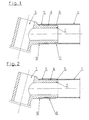
- the tube 1 is arranged over the neck 2 of the node 3.
- the circumferential adhesive gap 4 is delimited on both sides by press-fit surfaces 5, 6.
- the press-fit surface 5 at the pipe end has a larger diameter than the press-fit surface 6 and the rest of the attachment 2. This allows the pipe 1 to be coated with adhesive over which Approach 2 can be pushed without wiping the fit surface 6 by wiping it again.
- the tube 1 is provided in the area above the fitting surface 6 with a circumferential bead 7, whereby the press fit is made.
- a connection can be seen in the illustration in FIG. 2, in which the 1 tube has a widening 8 from the fitting surface 6 to its end. This creates the adhesive gap 4 and the mating surface 5.
- a circumferential undercut 9 is present at the extension 2, in which the tube 1 widened radially through the fitting surface 5 of the extension 2 springs in and thus creates an additional fixation of the tube 1 at the node 3.
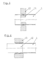
- FIG. 3 shows the production of the surrounding bead 7 by magnetic forming, the field converter 10 being arranged around the tube 1 and the calibration body 11 in the tube 1 in the area to be beaded.
- FIG. 4 shows an arrangement for expanding the tube, in which the coil 12 is mounted in the tube 1 and an annular calibration body 13 lies around the area of the tube 1 to be expanded.
- 5 and 6 show an embodiment of the connection with an interference fit surface 5 interrupted by grooves 14 and 15, respectively, at the knot attachment 2 in the region of the pipe end.
Landscapes
- Engineering & Computer Science (AREA)
- Mechanical Engineering (AREA)
- Mutual Connection Of Rods And Tubes (AREA)
Applications Claiming Priority (2)
| Application Number | Priority Date | Filing Date | Title |
|---|---|---|---|
| AT69290A AT394984B (de) | 1990-03-23 | 1990-03-23 | Verbindung zwischen rahmen und knoten von rohrrahmen, insbesondere fahrradrahmen |
| AT692/90 | 1990-03-23 |
Publications (1)
| Publication Number | Publication Date |
|---|---|
| EP0447951A1 true EP0447951A1 (fr) | 1991-09-25 |
Family
ID=3497309
Family Applications (1)
| Application Number | Title | Priority Date | Filing Date |
|---|---|---|---|
| EP91103891A Withdrawn EP0447951A1 (fr) | 1990-03-23 | 1991-03-14 | Raccordement entre des cadres et des joints tubulaires |
Country Status (2)
| Country | Link |
|---|---|
| EP (1) | EP0447951A1 (fr) |
| AT (1) | AT394984B (fr) |
Cited By (3)
| Publication number | Priority date | Publication date | Assignee | Title |
|---|---|---|---|---|
| DE4218304A1 (de) * | 1992-03-16 | 1993-09-23 | Austria Metall | Verfahren und vorrichtung zum verbinden von ineinander schiebbaren profilteilen |
| DE4420772A1 (de) * | 1994-06-15 | 1995-12-21 | Dieter Dr Ing Leibfried | Fahrradrahmen mit Schrumpfverbindungen |
| DE102004025312A1 (de) * | 2004-05-19 | 2006-02-09 | Braun Gmbh | Bauelement |
Citations (3)
| Publication number | Priority date | Publication date | Assignee | Title |
|---|---|---|---|---|
| DE802680C (de) * | 1948-06-02 | 1951-02-19 | Werner Dr-Ing Albert | Rohrmuffenverbindung, insbesondere fuer Fahrradrahmen |
| FR2254238A5 (en) * | 1973-12-07 | 1975-07-04 | Masson Claude | Assembly system for tubular motorbike frames - has tapering ends of tubes and junction piece clamped or glued together |
| US4900049A (en) * | 1987-01-13 | 1990-02-13 | Tseng Ike Diing Huang | Bicycle frame |
Family Cites Families (2)
| Publication number | Priority date | Publication date | Assignee | Title |
|---|---|---|---|---|
| US4583755A (en) * | 1984-12-04 | 1986-04-22 | Huffy Corporation | Bicycle frame |
| JPH01102089U (fr) * | 1987-12-28 | 1989-07-10 |
-
1990
- 1990-03-23 AT AT69290A patent/AT394984B/de not_active IP Right Cessation
-
1991
- 1991-03-14 EP EP91103891A patent/EP0447951A1/fr not_active Withdrawn
Patent Citations (3)
| Publication number | Priority date | Publication date | Assignee | Title |
|---|---|---|---|---|
| DE802680C (de) * | 1948-06-02 | 1951-02-19 | Werner Dr-Ing Albert | Rohrmuffenverbindung, insbesondere fuer Fahrradrahmen |
| FR2254238A5 (en) * | 1973-12-07 | 1975-07-04 | Masson Claude | Assembly system for tubular motorbike frames - has tapering ends of tubes and junction piece clamped or glued together |
| US4900049A (en) * | 1987-01-13 | 1990-02-13 | Tseng Ike Diing Huang | Bicycle frame |
Cited By (5)
| Publication number | Priority date | Publication date | Assignee | Title |
|---|---|---|---|---|
| DE4218304A1 (de) * | 1992-03-16 | 1993-09-23 | Austria Metall | Verfahren und vorrichtung zum verbinden von ineinander schiebbaren profilteilen |
| DE4420772A1 (de) * | 1994-06-15 | 1995-12-21 | Dieter Dr Ing Leibfried | Fahrradrahmen mit Schrumpfverbindungen |
| DE4420772C2 (de) * | 1994-06-15 | 1998-03-26 | Dieter Dr Ing Leibfried | Fahrradrahmen mit Schrumpfverbindungen |
| DE102004025312A1 (de) * | 2004-05-19 | 2006-02-09 | Braun Gmbh | Bauelement |
| DE102004025312B4 (de) * | 2004-05-19 | 2010-04-22 | Braun Gmbh | Bauelement |
Also Published As
| Publication number | Publication date |
|---|---|
| ATA69290A (de) | 1992-01-15 |
| AT394984B (de) | 1992-08-10 |
Similar Documents
| Publication | Publication Date | Title |
|---|---|---|
| EP0172134B1 (fr) | Douille en forme de tamis destinée à recevoir des éléments de fixation fixes au moyen de masses durcissables | |
| DE3938615C2 (fr) | ||
| DE69715780T2 (de) | Schnellkupplungsvorrichtung für eine unter mediendruck stehende flüssigkeitsleitung | |
| DE3014128C2 (fr) | ||
| EP0099529A1 (fr) | Partie de tuyau à manchon | |
| DE3226868A1 (de) | Dauerhaft dichte gewindelose rohrverbindung | |
| EP2018280B1 (fr) | Système d'assemblage sur un véhicule automobile entre une bague extérieure d'un palier à roulement et un support de roue et procédé de fabrication d'un système d'assemblage de ce type | |
| EP0557594B1 (fr) | Méthode de montage d'un élément de connexion | |
| DE2733556C3 (de) | Elastischer Dichtungsring | |
| WO2002073057A1 (fr) | Ensemble a soufflet | |
| EP1673185A1 (fr) | Procede et dispositif pour etablir une liaison serree entre tubes au niveau d'un raccord | |
| AT394984B (de) | Verbindung zwischen rahmen und knoten von rohrrahmen, insbesondere fahrradrahmen | |
| DE69008909T2 (de) | Verbindungsmittel für eine Farbrollerwiederladung und Farbroller mit dieser Wiederladung. | |
| EP1306601A2 (fr) | Raccords à compression pour la connection d'au moins un tuyau | |
| DE3203438A1 (de) | Verfahren zur herstellung einer metallmuffe aus einem zylindrischen rohrabschnitt | |
| DE2247850A1 (de) | Verfahren zum befestigen von endstuecken an zylindern | |
| EP0969222B1 (fr) | Arrangement de support pour dispositif de connexion et sa procédure de fabrication | |
| EP0450358A1 (fr) | Raccordement entre des cadres et des joints tubulaires, particulièrement pour des cadres de bicyclettes | |
| WO2000060265A1 (fr) | Dispositif de raccordement de tuyaux | |
| DE2602063A1 (de) | Sieb | |
| EP4049763B1 (fr) | Rouleau de peintre et procédé de montage d'un rouleau de peintre | |
| DE3219746A1 (de) | Spannhuelse | |
| DE3242072A1 (de) | Verbindungsanordnung fuer metallische rohre eines waermetauschers mit einem boden eines wasserkastens | |
| DE4429743A1 (de) | Stiftgelenk an einer hohlen Kolbenstange | |
| DE4319885A1 (de) | Verfahren zur Herstellung eines Gelenkaußenteils |
Legal Events
| Date | Code | Title | Description |
|---|---|---|---|
| PUAI | Public reference made under article 153(3) epc to a published international application that has entered the european phase |
Free format text: ORIGINAL CODE: 0009012 |
|
| 17P | Request for examination filed |
Effective date: 19910320 |
|
| AK | Designated contracting states |
Kind code of ref document: A1 Designated state(s): BE CH DE ES FR GB IT LI NL SE |
|
| 17Q | First examination report despatched |
Effective date: 19930824 |
|
| STAA | Information on the status of an ep patent application or granted ep patent |
Free format text: STATUS: THE APPLICATION IS DEEMED TO BE WITHDRAWN |
|
| 18D | Application deemed to be withdrawn |
Effective date: 19941001 |