EP0448002A1 - Dispositif d'enlèvement d'ordures - Google Patents
Dispositif d'enlèvement d'ordures Download PDFInfo
- Publication number
- EP0448002A1 EP0448002A1 EP91104118A EP91104118A EP0448002A1 EP 0448002 A1 EP0448002 A1 EP 0448002A1 EP 91104118 A EP91104118 A EP 91104118A EP 91104118 A EP91104118 A EP 91104118A EP 0448002 A1 EP0448002 A1 EP 0448002A1
- Authority
- EP
- European Patent Office
- Prior art keywords
- containers
- container
- disposal system
- gaps
- garbage
- Prior art date
- Legal status (The legal status is an assumption and is not a legal conclusion. Google has not performed a legal analysis and makes no representation as to the accuracy of the status listed.)
- Granted
Links
- 239000010813 municipal solid waste Substances 0.000 title claims description 66
- 238000013461 design Methods 0.000 claims description 76
- 239000002699 waste material Substances 0.000 claims description 40
- 230000008878 coupling Effects 0.000 description 4
- 238000010168 coupling process Methods 0.000 description 4
- 238000005859 coupling reaction Methods 0.000 description 4
- 238000011161 development Methods 0.000 description 4
- 230000018109 developmental process Effects 0.000 description 4
- 230000000087 stabilizing effect Effects 0.000 description 3
- 230000015572 biosynthetic process Effects 0.000 description 2
- 230000001771 impaired effect Effects 0.000 description 2
- 238000012549 training Methods 0.000 description 2
- 230000004308 accommodation Effects 0.000 description 1
- 238000006243 chemical reaction Methods 0.000 description 1
- 238000007654 immersion Methods 0.000 description 1
- 230000001788 irregular Effects 0.000 description 1
- 230000002045 lasting effect Effects 0.000 description 1
- 238000000034 method Methods 0.000 description 1
- 238000012856 packing Methods 0.000 description 1
Images


Classifications
-
- B—PERFORMING OPERATIONS; TRANSPORTING
- B65—CONVEYING; PACKING; STORING; HANDLING THIN OR FILAMENTARY MATERIAL
- B65F—GATHERING OR REMOVAL OF DOMESTIC OR LIKE REFUSE
- B65F1/00—Refuse receptacles; Accessories therefor
- B65F1/14—Other constructional features; Accessories
-
- B—PERFORMING OPERATIONS; TRANSPORTING
- B65—CONVEYING; PACKING; STORING; HANDLING THIN OR FILAMENTARY MATERIAL
- B65F—GATHERING OR REMOVAL OF DOMESTIC OR LIKE REFUSE
- B65F1/00—Refuse receptacles; Accessories therefor
- B65F1/12—Refuse receptacles; Accessories therefor with devices facilitating emptying
- B65F1/122—Features allowing the receptacle to be lifted and subsequently tipped by associated means on a vehicle
-
- B—PERFORMING OPERATIONS; TRANSPORTING
- B65—CONVEYING; PACKING; STORING; HANDLING THIN OR FILAMENTARY MATERIAL
- B65F—GATHERING OR REMOVAL OF DOMESTIC OR LIKE REFUSE
- B65F3/00—Vehicles particularly adapted for collecting refuse
- B65F3/02—Vehicles particularly adapted for collecting refuse with means for discharging refuse receptacles thereinto
- B65F3/04—Linkages, pivoted arms, or pivoted carriers for raising and subsequently tipping receptacles
-
- B—PERFORMING OPERATIONS; TRANSPORTING
- B65—CONVEYING; PACKING; STORING; HANDLING THIN OR FILAMENTARY MATERIAL
- B65F—GATHERING OR REMOVAL OF DOMESTIC OR LIKE REFUSE
- B65F2220/00—Properties of refuse receptacles
- B65F2220/12—Properties of refuse receptacles nestable
Definitions
- the invention relates to a garbage disposal system, consisting of garbage containers or containers, a garbage collection vehicle and a lifting and tipping device arranged on the latter, which temporarily has a bed receptacle forming a gripper or a gripping rail with a pouring rim design of the garbage container or container forming a receiving pocket can be coupled, which is located on the front wall of the container or container body opposite the hinges for a hinged lid.
- the receiving pocket or pouring rim design of the waste containers or containers used in such waste disposal systems is in the area of engagement of the gripper or the gripping rail or the bulk pick-up by individual ribs or webs or else by ribs or web systems in several along the front of the Container or Container hull divided pocket sections divided.
- waste disposal systems primarily aim at the design of the waste containers or containers in the sense of increasing their value in use, because these are system elements that are not within the respective waste disposal system are only used in relatively large numbers, but also form the most sensitive link in the disposal chain.
- Another possibility for the disposal of garbage containers or containers with different pouring rim designs that are in use at the same time is to assign special adapters to the bed receptacles of the lifting and tipping devices, which are matched to the pouring rim design of a particular type of rubbish container or container that is in use next to one another.
- the adapter on the refuse collection vehicle must be kept available at all times, and in such a way that it has to be plugged in or removed from the refuse collectors in an irregular sequence, as required, onto the usual bulk pick-up.
- the invention has for its object to provide a garbage disposal system, which makes it possible to use not only garbage containers or containers with each lifting and tipping device operated on a garbage collection vehicle and using only one embodiment of fill receptacles to easily dispose of different pouring rim designs, but also to enable the disposal of garbage containers or containers of different capacities and thus different sizes.
- this object can be achieved according to the invention by the characterizing features of claim 1, that is to say, that the bed receptacle designed as a gripper or gripping rail of the lifting and tipping device along its edge region associated with the receiving pocket or pouring rim design of the waste container or container with both parallel as well as toothing contours oriented transversely to their main plane, the head surfaces of the toothing contour oriented essentially transverse to the main plane of the toothing contour oriented parallel to this main plane and the end faces of the toothing contour oriented transversely to the main plane lying on a common straight line on the one hand, while the boundary surfaces of the tooth gaps that spring back from these straight lines each have a shape which is based on the position of the individual ribs or webs and / or ribs or web systems on different waste containers n or containers is coordinated.
- the measures according to the invention proposal make it possible to continue to use the waste containers or containers already in use when they are reintegrated into an existing waste disposal system until they become unusable, simply because that the lifting and tipping devices are exchanged for the old bed receptacles for novel bed receptacles according to the invention is because these are also compatible with the design of the dumping rim of the existing garbage containers.
- the invention further proposes according to claim 2 that the toothing contour oriented in the direction of the main plane of the bed receptacle consists of four trapezoidally limited teeth and three tooth gaps, the two outer tooth gaps also having a trapezoidal shape, while the middle tooth gap has at least approximately a triangular shape.
- the mean tooth gap has a depth which is a multiple, e.g. corresponds to three to four times the depth of each outer tooth gap.
- the greatest width of the central - triangular - tooth space is dimensioned to be substantially larger than the greatest width of the two outer tooth spaces, for example approximately twice the same.
- toothing contour oriented transversely to the main plane of the bed receptacle is limited by four teeth and four gaps and the two outer gaps each lie in the area of an outer tooth gap of the other toothing contour, while the two inner gaps connect to the flanks of the middle tooth gap of the other toothing contour.
- the two outer gaps each have the shape of a pyramid-like groove which diverges from bottom to top, while the two middle gaps consist of flank incisions on the middle tooth gap of the other toothing contour which face in the direction the main plane of the bed pick-up delimit the outline shape of a right-angled triangle with its tip pointing upwards, while defining a right-angled triangle with its tip pointing downwards transversely to the main plane of the bed pick-up.
- Another feature of the invention is characterized according to claim 9, characterized in that the inner flank of the two outer gaps is arranged in a straight line extension of the inner flank of an outer tooth gap of the other toothing contour.
- the total width of the bed intake in the area of its toothing contour oriented in the direction of the main plane is matched to the width of the pouring rim design of refuse containers or containers with an average capacity of, for example, 0.12 to 0.24 m3 , while the outer tooth gaps of this toothing contour each have an opening width which is at least the profile cross section of the adjoining the pouring rim design along the side walls of the container or container body Stiffening collar corresponds.
- the distance between the outer flank of an outer tooth and the inner flank of the outer tooth gap adjacent to the other outer tooth should be matched to the light dimension of the pouring rim design on a waste container or container with a small capacity of, for example, 0.08 m3.
- the distance between the inner flanks of the two outer tooth gaps is also matched to the light dimension of the rim design on a waste container or container with a small capacity of, for example, 0.08 m3.
- An essential feature of the invention of the garbage disposal system is characterized according to claim 13 by garbage containers or containers, the pouring rim design of which forms the receiving pocket and has a central rib or web system which tapers approximately triangularly at the bottom and which has a support and centering engagement for the central, forms approximately a triangular tooth gap in the bed receptacle on the lifting and tilting device.
- the invention also provides that the outer wall of the pouring rim design forming the receiving pocket is also approximately flat-triangular downwards has tapered boundary and is provided on the outside with stiffening ribs or webs distributed over the entire surface. This results in a highly stable design of the pouring rim design on the garbage containers or bins.
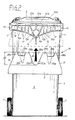
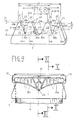
- FIG. 1 of the drawing which comprises waste collection vehicles 1 with lifting and tipping devices 2 and bed receptacles 3 mounted thereon as well as several, for example four, different waste containers or containers 4a, 4b, 4c as system elements , 4d belong.
- the garbage containers or containers 4a and 4b belong to a conventional older type, while the garbage containers or containers 4c and 4d belong to a new, improved type.
- the two garbage containers or containers 4a and 4c have a corresponding, for example average filling volume, which can be, for example, between 0.12 and 0.24 m 3, while the garbage containers or containers 4b and 4d for a smaller capacity, for example.
- waste disposal system can also include waste containers or containers that are designed for large filling volumes, for example 0.36 m3.
- Each version or type of waste container or container 4a to 4d belonging to the waste disposal system has a container or container body 6 which can be closed by a hinged lid 5 and is also provided with a pair of impellers 7 on the latter.
- each refuse container or container 4a to 4d has on its front wall 8 opposite the hinges for the hinged lid 5 a pouring rim design 9a or 9b which can be designed, for example, as a receiving pocket.
- Each bulk intake 9a or 9b forms a coupling engagement for the bed receptacle 3, designed as a gripper or gripping rail, of a lifting and tipping device.
- the pouring rim designs 9a and 9b merge towards the side walls of the container or container body 6 into the stiffening collar 10, which extends both along the side walls and along the rear wall of the container or container body 6 in the region of the container opening.
- the design of the stiffening collar 10 can be conventional and is therefore not explained in detail here.
- the pouring rim design 9a on the two garbage bins or containers 4a and 4b have a structurally identical basic design with regard to the profile and dimensions of their receiving pocket, however, due to the different capacities of their container or container body 6, they have certain different features.
- the pouring rim design 9a 'of the refuse container or container 4a is equipped with individual ribs or webs 12' which have a different arrangement and design than the individual ribs or webs 12 '' on the waste container or container 4b.
- the individual ribs or webs 12 'and 12' ' serve to stiffen and stabilize the respective pouring rim design 9a' or 9a '' against the container or container hull 6.
- the pouring rim design 9a 'or 9a' ' is subdivided into a plurality of pocket sections provided along the front side 8 of the container or container body 6.
- the pouring rim designs 9b on the garbage containers or containers 4c and 4d can in principle be designed to be the same, with differences only in terms of their overall length, which in turn is determined by the fact that the containers or container hulls 6 have different capacities must have different cross sections at approximately the same height.
- FIG. 3 of the drawing shows, on an enlarged scale, the design features of the pouring rim design 9a 'of the garbage container or container 4a according to FIG. 1, while, also on a larger scale, the pouring rim design 9a''of the garbage container or container 4b according to FIG. 1 is shown in Fig. 5.
- 6 also shows training features of the pouring rim design 9a 'and from FIG. 7 also features of the pouring rim design 9a''according to FIG. 1.
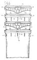
- FIG. 8 of the drawing in a detailed spatial rear view, the formation of a bed receptacle 3 effective as a gripper or gripping rail can be seen, as is provided on the lifting and tilting devices 2 of the refuse collection vehicles 1, in order to provide the temporary coupling connection with the various pouring rim designs 9a and 9a ', 9a' 'and 9b of the garbage containers or containers 4a, 4b, 4c and 4d which can be used simultaneously within the garbage disposal system.
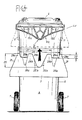
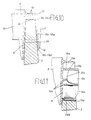
- the special characteristic of the design of the pouring rim 9b on the front wall 8 of the refuse containers 4c and 4d according to FIG. 1 is that there is a central rib on each container or container body 6, that is to say located on the vertical longitudinal center plane and tapering downward in an approximately triangular manner. or web system 13 is provided, which forms a support and centering engagement 14 for the bed receptacles 3 located on the lifting and tilting devices 2 of the refuse collection vehicle 1.
- the rib or web system 13 of this support and centering engagement 14 is, as can be seen in particular in FIG. 11 of the drawing, directly integrally formed on the front wall 8 of the container or container body 6, in such a way that it essentially protrudes transversely from the plane of the front wall 8.
- the rib or web system 13 of the support and centering engagement 14 is formed by a surrounding rib 13a delimiting its triangular shape and by a multiplicity of stiffening or stabilizing webs 13b, which are arranged in a mesh-like manner within the surrounding rib 13a.
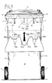
- the support and centering engagement 14 is spaced from the front wall 8 of the container or container body 6 by a wall section 15a or 15b, these two wall sections 15a and 15b each being mirror images of one another and symmetrical to one another Longitudinal center plane through the support and centering engagement 14 are arranged.
- These wall sections 15a and 15b each adjoin at the bottom to the stiffening collar 10, which usually runs around the filling opening of the container or container body 6 and contains a stabilizing rib 16 on the underside, as can be clearly seen in FIG. 10.
- Each of the two wall sections 15a and 15b is provided on the outside with stiffening ribs 17, e.g. vertically extending, distributed over its entire surface, and its lower limiting rib 18 has such a slightly curved course that the two wall sections 15a and 15b are approximately receive a flat-triangular downward tapered boundary that tapers to the side walls at the level of the lower edge of the stiffening collar 10.
- a downwardly open receiving pocket section 19a or 19b of the pouring rim design 9b is formed to the side next to the support and centering engagement 16, into which the bulk receiving 3 a stroke -Tilting device 2 can be retracted (Fig. 10).
- the pouring edge design 9b on the container or container hulls 6 of the garbage containers or containers 4c and 4d it has also proven to be important that the downward triangular tips both of the support and centering engagement 14 and also of the wall sections 15a, 15b lie somewhat above the lower ends of the stacking webs 11 formed on the outer circumference of the container or container body. This ensures, as shown in FIGS. 6 and 7, that in the case of a column-like interlocking of several empty garbage containers or containers, the impact of these triangular tips on the stiffening collar 10 of the next lower garbage container or container is avoided.
- garbage containers or containers 4c and 4d with the particularly advantageous pouring rim design can be easily integrated into a garbage disposal system if required, which previously only included garbage containers or containers 4a and 4b with pouring rim designs 9a 'and 9a' 'as system elements the use of bed receptacles 3 designed as a gripper or gripping rail is provided on the lifting and tilting devices 2 and is compatible with each of the pouring rim designs 9a ', 9a' 'and 9b.
- a bulk receptacle 3 designed in this way, forming a gripper or a gripping rail, is shown in a spatial rear view in FIG. 8 of the drawing, but can also be seen in a schematically simplified front view in FIGS. 2 to 5 and 9 of the drawing.
- the bed receptacle 3 of the lifting and tilting device (not shown) designed as a gripper or gripping rail is equipped with a toothing contour 22 oriented parallel to its main plane over its vertical edge region 20.
- the bed holder 3 also has a toothing contour 23 oriented transversely to the main plane over its horizontal edge region 21.
- the toothed contour 22 oriented in the direction of the main plane of the fill receptacle 3 in the illustrated embodiment consists of four trapezoidally limited teeth 28a and 28b and three tooth gaps 29a and 29b.
- the design of the two outer teeth 28a is somewhat narrower than the two middle teeth 28b.
- the two outer tooth gaps 29a each have a matching trapezoidal shape, while the middle tooth gap 29b has at least approximately a downwardly diverging triangular shape, which is adapted to the contour of the support and centering interventions 14 of the pouring rim design 9b for the waste containers or containers 4c and 4d.
- the central tooth gap 29b measured from the top surfaces 24 lying on the common straight line 25, has a depth that extends over the entire vertical edge region 20 extends. It corresponds to a multiple, e.g. three to four times the depth 30 for the two outer tooth gaps 29a and 29b.
- the outer trapezoidal flank 31 of the two outer teeth 28a extends with a constant inclined position at least approximately over the entire height of the bed receptacle 3 and that the greatest width 32 of the central tooth gap 29b is substantially greater than the greatest width 33 of the two outer tooth gaps 29a is dimensioned, for example corresponds approximately to twice the same.
- the toothing contour 23 oriented transversely to the main plane of the fill receptacle 3 is delimited by four teeth 34a and 34b and four gaps 35a and 35b.
- the two outer gaps 35a are each arranged in the area of an outer tooth gap 29a of the other toothing contour 22, while the two inner gaps 35b connect to the flanks of the middle tooth gap 29b of the other toothing contour 22.
- the two outer gaps 35a of the toothing contour 23 each have approximately the shape of a groove which diverges from bottom to top in a pyramid-like manner, while the two middle gaps 35b consist of flank incisions on the middle tooth gap of the other toothing contour 22.
- the middle gaps in the direction of the main plane of the fill receptacle 3 have the outline shape of a right-angled triangle with its tip pointing upwards, while they Determine a right-angled triangle with its tip pointing transversely to the main plane of the fill receptacle 3.
- the inner flank of the two outer gaps 35a is arranged in a straight line extension of the inner flank of an outer tooth gap 29a of the other toothing contour 22.
- the overall width 36 of the fill receptacle 3 in the region of its toothing contour 22 oriented in the direction of the main plane corresponds to the overall width of the pouring rim design 9a 'or 9b of refuse containers or containers 4a and 4c with an average capacity of 0, for example. 12 to 0.24 m3 is tuned.
- the outer tooth gaps 29a of this toothing contour 22 each have an opening width which corresponds at least to the profile cross section of the stiffening collar 10 adjoining the pouring rim design 9a 'and 9b along the side walls of the container or container body 6.
- the distance 37 between the outer flank of an outer tooth 28a and the inner flank of the outer tooth gap 29a adjacent to the other outer tooth 28a is advantageously based on the light dimension of the pouring rim design 9a ′′ or 9b on a waste container or container 4b or 4d small capacity, for example 0.08 m3, coordinated.
- the distance 38 between the outer flanks of the two outer tooth gaps 29a should also be matched to the light dimension of the pouring rim design 9a ′′ or 9b on a waste container or container 4b or 4d with a small capacity of, for example, 0.08 m3. 2, 4 and 9 of the drawing make it clear that when the bed holder 3 is retracted, in the pouring rim design 9b the middle tooth gap 29b of the toothing contour 22 engages on the support or centering engagement 14, while the adjacent teeth 28a, 28b and tooth gaps 29a dip into the receiving pocket sections 19a and 19b, which are respectively delimited from the outside by the wall sections 15a and 15b .
- the head surfaces 24 of the teeth 28a and 28b come to bear on the stabilizing rib 16, which are located above the receiving pocket sections 19a and 19b within the stiffening collar 10.
- the pouring rim design 9b formed from the middle support and centering engagement 14, the two wall sections 15a, 15b and the receiving pocket sections 19a and 19b offers the refuse containers or containers 4c and 4d each a secure and stable hold on the packing receptacle 3 during the total working movement of the lifting and tipping device 2.
- tooth gaps 29a and 29b of the toothing contour 22 as well as the gaps 35a and 35b of the toothing contour 23 have no functional meaning when the bed receptacle 3 interacts with the pouring rim design 9b of the garbage containers or containers 4c and 4d.
- tooth gaps 29a of the toothing contour 22 and the tooth gaps 35a and 35 of the toothing contour 23 for the use of the bulk holder 3 in connection with refuse containers or containers 4a and 4b, which have a pouring rim design 9a or 9a 'and 9a'' , as is illustrated by FIGS. 3 and 5 of the drawing.
- the toothing contour 22 comes into coupling engagement via its four teeth 28a and 28b when the bed receptacle 3 is retracted, while the middle tooth gap 29b forms a free space for the immersion of the middle single rib or the middle single web 12 '.
- the two outer gaps 35a of the other toothing contour 23 act as receptacles for the two outer individual ribs 12 '.
- the offset position is such that one of the outer teeth 28a of the toothing contour 22 comes to lie laterally outside the stiffening collar, so that the latter dips into the adjacent, external tooth gap 29a.
- the remaining three teeth 28a and 28b come into engagement with the pouring rim design 9a ′′ in such a way that the left single rib or the left individual web 12 ′′ of the pouring rim design 9a ′′ comes into one, namely the left gap 35b of the toothing contour 23 immerses while the other individual rib or the other individual web 12 ′′ comes to rest in the right outer gap 35a of this toothing contour 23.
- the usability of the fill receptacles provided with the two toothed contours 22 and 23 can be achieved in particular in that, in the newly designed refuse containers or containers 4c and 4d, the pouring rim design 9b is provided with the support and centering engagement 14 tapering downwards in a triangular shape, which can dip into the appropriately contoured, central tooth gap 29b of the toothing contour 22 in the bed receptacle 3.
- the newly designed refuse containers or containers 4c and 4d also have a pouring rim design 9b which forms the receiving pocket 19a, 19b compared to the illustrations in the drawing, in particular FIGS. 2, 4 and 9 to 11 modified version can be obtained, provided that the bed receptacle 3 of the lifting and tilting device 2, designed as a gripper or gripping rail, is given a version adapted to it.
- the two outer tooth gaps 29a it would of course be necessary for the two outer tooth gaps 29a to be given a triangular shape instead of the trapezoidal shape, which is at least similar to the triangular shape, as shown in the drawing, on the bed receptacle 3 designed as a gripper or gripping rail has middle tooth gap 29b.
- the fill receptacle 3 would only have to be designed in such a way that the toothing contour 23, 35a, 35b oriented transversely to the main plane provided damage-free accommodation of the individual ribs or webs 12 'or 12' ' the conventional, older design of waste containers or containers 4a and 4b.
Landscapes
- Engineering & Computer Science (AREA)
- Mechanical Engineering (AREA)
- Refuse-Collection Vehicles (AREA)
- Processing Of Solid Wastes (AREA)
- Refuse Collection And Transfer (AREA)
Priority Applications (1)
| Application Number | Priority Date | Filing Date | Title |
|---|---|---|---|
| AT91104118T ATE84274T1 (de) | 1990-03-21 | 1991-03-16 | Muell-entsorgungssystem. |
Applications Claiming Priority (2)
| Application Number | Priority Date | Filing Date | Title |
|---|---|---|---|
| DE4009060A DE4009060A1 (de) | 1990-03-21 | 1990-03-21 | Muell-entsorgungssystem |
| DE4009060 | 1990-03-21 |
Publications (2)
| Publication Number | Publication Date |
|---|---|
| EP0448002A1 true EP0448002A1 (fr) | 1991-09-25 |
| EP0448002B1 EP0448002B1 (fr) | 1993-01-07 |
Family
ID=6402726
Family Applications (1)
| Application Number | Title | Priority Date | Filing Date |
|---|---|---|---|
| EP91104118A Expired - Lifetime EP0448002B1 (fr) | 1990-03-21 | 1991-03-16 | Dispositif d'enlèvement d'ordures |
Country Status (5)
| Country | Link |
|---|---|
| US (1) | US5165835A (fr) |
| EP (1) | EP0448002B1 (fr) |
| AT (1) | ATE84274T1 (fr) |
| CA (1) | CA2038705A1 (fr) |
| DE (2) | DE4009060A1 (fr) |
Cited By (3)
| Publication number | Priority date | Publication date | Assignee | Title |
|---|---|---|---|---|
| EP0624530A1 (fr) * | 1993-05-10 | 1994-11-17 | OTTO LIFT-SYSTEME GmbH | Dispositif de prise de réceptacles monté sur un véhicule de ramassage d'ordures pour vider les réceptacles |
| EP2801541A1 (fr) * | 2013-05-07 | 2014-11-12 | ESE World B.V. | Dispositif de levage destiné à un récipient de collecte de déchets et récipient de collecte de déchets |
| WO2015158673A1 (fr) * | 2014-04-16 | 2015-10-22 | Fritz Schäfer GmbH | Bac à ordures avec corps en matière plastique moulé par injection |
Families Citing this family (6)
| Publication number | Priority date | Publication date | Assignee | Title |
|---|---|---|---|---|
| DE19510359A1 (de) * | 1995-03-22 | 1996-09-26 | Otto Geb Kg | Vorrichtung zum automatischen Positionieren eines Schwenkarmes |
| DE19624723A1 (de) * | 1996-06-21 | 1998-01-02 | Otto Geb Kg | Müllbehälter und Aufnahmesystem für Müllbehälter |
| US9371181B2 (en) | 2007-04-05 | 2016-06-21 | Jake, Connor & Crew, Inc. | Secure accumulation/disposal bin |
| USD594169S1 (en) | 2007-04-05 | 2009-06-09 | Jake's Holding Corporation | Accumulation bin |
| US20080273955A1 (en) * | 2007-05-02 | 2008-11-06 | International Truck Intellectual Property Company, Llc. | Refuse collection device and disposal method for public transportation vehicles |
| US8474892B1 (en) * | 2012-06-13 | 2013-07-02 | Pinnacle Companies, Inc. | Lifting apparatus and method |
Citations (5)
| Publication number | Priority date | Publication date | Assignee | Title |
|---|---|---|---|---|
| EP0098528A2 (fr) * | 1982-07-03 | 1984-01-18 | Bartholomäus Bitsch | Récipient à ordures |
| EP0178491A1 (fr) * | 1984-10-05 | 1986-04-23 | Willem Jan Achterberg | Récipient à ordures |
| EP0185382A2 (fr) * | 1984-12-21 | 1986-06-25 | Edelhoff M.S.T.S. Gmbh | Adaptateur pour poubelles |
| US4613271A (en) * | 1985-03-21 | 1986-09-23 | Zoller-Kipper Gmbh | Universal device to empty different-style garbage containers |
| DE3703034C1 (de) * | 1987-02-02 | 1988-04-14 | Otto Geb Kg | Muellbehaelter mit einer nach unten offenen Aufnahmetasche zum Eingriff eines Greifers |
Family Cites Families (16)
| Publication number | Priority date | Publication date | Assignee | Title |
|---|---|---|---|---|
| US3016157A (en) * | 1957-12-19 | 1962-01-09 | Lodal Inc | Loader apparatus |
| SE378801B (fr) * | 1971-04-01 | 1975-09-15 | Norba Ab | |
| US3874534A (en) * | 1973-09-13 | 1975-04-01 | Lodal Inc | Fail-safe locking arrangement for refuse collection vehicle |
| AU8165882A (en) * | 1982-03-18 | 1983-09-22 | Wastemovers Pty. Ltd. | Container handling device |
| DE3420058A1 (de) * | 1984-05-29 | 1985-12-05 | Edelhoff Polytechnik GmbH & Co, 5860 Iserlohn | Motorgetriebenes muellsammelfahrzeug mit als wechselbehaelter ausgebildeten containern |
| DE3527022A1 (de) * | 1984-08-21 | 1986-03-06 | Zöller-Kipper GmbH, 6500 Mainz | Kipp- oder hubkipp-vorrichtung zum entleeren von behaeltern in sammelbehaelter, vorzugsweise muellbehaelter in den sammelbehaelter eines muellfahrzeugs |
| GB2165814B (en) * | 1984-10-20 | 1988-06-08 | Allen Jack | Refuse container lifting apparatus |
| US4687405A (en) * | 1985-06-24 | 1987-08-18 | Olney David I | Trash can dumping apparatus |
| EP0230663B1 (fr) * | 1986-01-31 | 1990-11-07 | VALLE TEIRO S.r.l. | Dispositif pour soulever, basculer et décharger des récipients à ordures dans un véhicule à ordures, comportant une pièce coulissante, un ou plusieurs bras de levier et une tête de préhension triangulaire oscillante et mobile transversalement |
| DE3629291A1 (de) * | 1986-08-28 | 1988-03-10 | Zoeller Kipper | Hubkipp- oder kippvorrichtung zum entleeren von behaeltern, die mit einer trennwand versehen sind |
| DE3639861A1 (de) * | 1986-11-21 | 1988-06-01 | Zoeller Kipper | Hubkipp- oder kippvorrichtung zum entleeren von behaeltern, insbesondere muellbehaeltern, in einen sammelbehaelter |
| DE3703795A1 (de) * | 1987-02-07 | 1988-08-18 | Zoeller Kipper | Schutzvorrichtung fuer eine hubkipp- oder kippvorrichtung |
| EP0288066B1 (fr) * | 1987-04-22 | 1992-09-02 | Edelhoff M.S.T.S. Gmbh | Récipient à ordures |
| GB8724360D0 (en) * | 1987-10-17 | 1987-11-18 | Allen Motor Bodies Ltd Jack | Collection vehicle & method of tipping bin |
| DE3881518D1 (de) * | 1988-08-10 | 1993-07-08 | Otto Lift Systeme Gmbh | Muellbehaelter mit klappdeckel sowie greifeinrichtung einer hub-kippvorrichtung zum entleeren desselben. |
| US4983092A (en) * | 1988-08-18 | 1991-01-08 | Jayrich Engineering Pty Ltd. | Retractable arm/loader assembly |
-
1990
- 1990-03-21 DE DE4009060A patent/DE4009060A1/de not_active Withdrawn
-
1991
- 1991-03-16 AT AT91104118T patent/ATE84274T1/de active
- 1991-03-16 DE DE9191104118T patent/DE59100026D1/de not_active Expired - Fee Related
- 1991-03-16 EP EP91104118A patent/EP0448002B1/fr not_active Expired - Lifetime
- 1991-03-20 US US07/678,540 patent/US5165835A/en not_active Expired - Fee Related
- 1991-03-20 CA CA002038705A patent/CA2038705A1/fr not_active Abandoned
Patent Citations (5)
| Publication number | Priority date | Publication date | Assignee | Title |
|---|---|---|---|---|
| EP0098528A2 (fr) * | 1982-07-03 | 1984-01-18 | Bartholomäus Bitsch | Récipient à ordures |
| EP0178491A1 (fr) * | 1984-10-05 | 1986-04-23 | Willem Jan Achterberg | Récipient à ordures |
| EP0185382A2 (fr) * | 1984-12-21 | 1986-06-25 | Edelhoff M.S.T.S. Gmbh | Adaptateur pour poubelles |
| US4613271A (en) * | 1985-03-21 | 1986-09-23 | Zoller-Kipper Gmbh | Universal device to empty different-style garbage containers |
| DE3703034C1 (de) * | 1987-02-02 | 1988-04-14 | Otto Geb Kg | Muellbehaelter mit einer nach unten offenen Aufnahmetasche zum Eingriff eines Greifers |
Cited By (3)
| Publication number | Priority date | Publication date | Assignee | Title |
|---|---|---|---|---|
| EP0624530A1 (fr) * | 1993-05-10 | 1994-11-17 | OTTO LIFT-SYSTEME GmbH | Dispositif de prise de réceptacles monté sur un véhicule de ramassage d'ordures pour vider les réceptacles |
| EP2801541A1 (fr) * | 2013-05-07 | 2014-11-12 | ESE World B.V. | Dispositif de levage destiné à un récipient de collecte de déchets et récipient de collecte de déchets |
| WO2015158673A1 (fr) * | 2014-04-16 | 2015-10-22 | Fritz Schäfer GmbH | Bac à ordures avec corps en matière plastique moulé par injection |
Also Published As
| Publication number | Publication date |
|---|---|
| US5165835A (en) | 1992-11-24 |
| CA2038705A1 (fr) | 1991-09-22 |
| DE59100026D1 (de) | 1993-02-18 |
| DE4009060A1 (de) | 1991-09-26 |
| ATE84274T1 (de) | 1993-01-15 |
| EP0448002B1 (fr) | 1993-01-07 |
Similar Documents
| Publication | Publication Date | Title |
|---|---|---|
| DE8614126U1 (de) | Behälter, insbesondere Farbkasten | |
| DE3614328C2 (de) | Schüttung an einem Müllfahrzeug und Müllbehälter für diese Schüttung | |
| DE9013289U1 (de) | Box zur Aufnahme von Schraubendrehereinsätzen | |
| EP1018473A1 (fr) | Agencement de récipient | |
| EP0448002B1 (fr) | Dispositif d'enlèvement d'ordures | |
| EP4353628A1 (fr) | Dispositif de récipient d'insertion pour un récipient de collecte de déchets et récipient de collecte de déchets | |
| WO1995031388A1 (fr) | Vehicule de collecte des dechets | |
| EP4349736A1 (fr) | Dispositif de récipient d'insertion pour un récipient de collecte de déchets et récipient de collecte de déchets | |
| DE69208685T2 (de) | Vorrichtung zum sammeln von abfall,insbesondere von glasverpackungen | |
| EP0632786A1 (fr) | Recipient stable, notamment une poubelle. | |
| EP0178491B1 (fr) | Récipient à ordures | |
| EP0505585A1 (fr) | Réceptacle avec couvercle frontal transparent et refermable | |
| DE2556449A1 (de) | Flaschenkasten | |
| EP0624530B1 (fr) | Dispositif de prise de réceptacles monté sur un véhicule de ramassage d'ordures pour vider les réceptacles | |
| EP0517166B1 (fr) | Récipient pour déchets | |
| DE4218742A1 (de) | System zur Entsorgung von Altstoffen | |
| DE3924103A1 (de) | Nachfuelleinheit mit in einer loesbaren halterung sitzenden pipettenspitzen fuer einen autoklavierbaren behaelter | |
| DE69402203T2 (de) | Grossmüllbehälter | |
| DE1481241A1 (de) | Beutelhalter | |
| DE3843853C2 (de) | Dose | |
| DE3004673C2 (fr) | ||
| DE3641132C2 (de) | Regal zur Aufbewahrung von plattenförmigen Körpern | |
| DE9211480U1 (de) | Hebe- und Entleervorrichtung für einen Abfall-Sammelbehälter | |
| DE898577C (de) | Zerlegbare Kiste | |
| AT390774B (de) | Abfallsammelbehaelter |
Legal Events
| Date | Code | Title | Description |
|---|---|---|---|
| PUAI | Public reference made under article 153(3) epc to a published international application that has entered the european phase |
Free format text: ORIGINAL CODE: 0009012 |
|
| 17P | Request for examination filed |
Effective date: 19910328 |
|
| AK | Designated contracting states |
Kind code of ref document: A1 Designated state(s): AT BE CH DE DK ES FR GB GR IT LI LU NL SE |
|
| 17Q | First examination report despatched |
Effective date: 19920422 |
|
| GRAA | (expected) grant |
Free format text: ORIGINAL CODE: 0009210 |
|
| AK | Designated contracting states |
Kind code of ref document: B1 Designated state(s): AT BE CH DE DK ES FR GB GR IT LI LU NL SE |
|
| PG25 | Lapsed in a contracting state [announced via postgrant information from national office to epo] |
Ref country code: DK Effective date: 19930107 Ref country code: IT Free format text: LAPSE BECAUSE OF FAILURE TO SUBMIT A TRANSLATION OF THE DESCRIPTION OR TO PAY THE FEE WITHIN THE PRE;WARNING: LAPSES OF ITALIAN PATENTS WITH EFFECTIVE DATE BEFORE 2007 MAY HAVE OCCURRED AT ANY TIME BEFORE 2007. THE CORRECT EFFECTIVE DATE MAY BE DIFFERENT FROM THE ONE RECORDED.SCRIBED TIME-LIMIT Effective date: 19930107 Ref country code: ES Free format text: THE PATENT HAS BEEN ANNULLED BY A DECISION OF A NATIONAL AUTHORITY Effective date: 19930107 Ref country code: NL Effective date: 19930107 Ref country code: GB Effective date: 19930107 Ref country code: GR Free format text: LAPSE BECAUSE OF FAILURE TO SUBMIT A TRANSLATION OF THE DESCRIPTION OR TO PAY THE FEE WITHIN THE PRESCRIBED TIME-LIMIT Effective date: 19930107 Ref country code: BE Effective date: 19930107 Ref country code: FR Effective date: 19930107 |
|
| REF | Corresponds to: |
Ref document number: 84274 Country of ref document: AT Date of ref document: 19930115 Kind code of ref document: T |
|
| REF | Corresponds to: |
Ref document number: 59100026 Country of ref document: DE Date of ref document: 19930218 |
|
| PG25 | Lapsed in a contracting state [announced via postgrant information from national office to epo] |
Ref country code: AT Effective date: 19930316 |
|
| PG25 | Lapsed in a contracting state [announced via postgrant information from national office to epo] |
Ref country code: SE Effective date: 19930317 |
|
| PG25 | Lapsed in a contracting state [announced via postgrant information from national office to epo] |
Ref country code: CH Effective date: 19930331 Ref country code: LI Effective date: 19930331 Ref country code: LU Free format text: LAPSE BECAUSE OF NON-PAYMENT OF DUE FEES Effective date: 19930331 |
|
| EN | Fr: translation not filed | ||
| NLV1 | Nl: lapsed or annulled due to failure to fulfill the requirements of art. 29p and 29m of the patents act | ||
| GBV | Gb: ep patent (uk) treated as always having been void in accordance with gb section 77(7)/1977 [no translation filed] |
Effective date: 19930107 |
|
| PLBE | No opposition filed within time limit |
Free format text: ORIGINAL CODE: 0009261 |
|
| STAA | Information on the status of an ep patent application or granted ep patent |
Free format text: STATUS: NO OPPOSITION FILED WITHIN TIME LIMIT |
|
| REG | Reference to a national code |
Ref country code: CH Ref legal event code: PL |
|
| PG25 | Lapsed in a contracting state [announced via postgrant information from national office to epo] |
Ref country code: DE Effective date: 19931201 |
|
| 26N | No opposition filed | ||
| EUG | Se: european patent has lapsed |
Ref document number: 91104118.4 Effective date: 19931008 |