EP0448077B1 - Plasmatron à micro-ondes - Google Patents
Plasmatron à micro-ondes Download PDFInfo
- Publication number
- EP0448077B1 EP0448077B1 EP19910104340 EP91104340A EP0448077B1 EP 0448077 B1 EP0448077 B1 EP 0448077B1 EP 19910104340 EP19910104340 EP 19910104340 EP 91104340 A EP91104340 A EP 91104340A EP 0448077 B1 EP0448077 B1 EP 0448077B1
- Authority
- EP
- European Patent Office
- Prior art keywords
- microwave
- microwave plasmatron
- magnets
- surface waveguide
- plasmatron according
- Prior art date
- Legal status (The legal status is an assumption and is not a legal conclusion. Google has not performed a legal analysis and makes no representation as to the accuracy of the status listed.)
- Expired - Lifetime
Links
- 238000004157 plasmatron Methods 0.000 title claims description 31
- 230000005291 magnetic effect Effects 0.000 claims description 22
- 238000000605 extraction Methods 0.000 claims description 8
- 229910052751 metal Inorganic materials 0.000 claims description 4
- 239000002184 metal Substances 0.000 claims description 4
- 239000003302 ferromagnetic material Substances 0.000 claims description 2
- 230000008878 coupling Effects 0.000 description 15
- 238000010168 coupling process Methods 0.000 description 15
- 238000005859 coupling reaction Methods 0.000 description 15
- 230000005684 electric field Effects 0.000 description 12
- 230000004907 flux Effects 0.000 description 10
- 230000003068 static effect Effects 0.000 description 10
- XEEYBQQBJWHFJM-UHFFFAOYSA-N Iron Chemical compound [Fe] XEEYBQQBJWHFJM-UHFFFAOYSA-N 0.000 description 7
- 239000004020 conductor Substances 0.000 description 5
- 238000009826 distribution Methods 0.000 description 5
- 230000005284 excitation Effects 0.000 description 4
- 239000007789 gas Substances 0.000 description 4
- 239000011810 insulating material Substances 0.000 description 4
- 229910052742 iron Inorganic materials 0.000 description 3
- OKTJSMMVPCPJKN-UHFFFAOYSA-N Carbon Chemical compound [C] OKTJSMMVPCPJKN-UHFFFAOYSA-N 0.000 description 2
- VYPSYNLAJGMNEJ-UHFFFAOYSA-N Silicium dioxide Chemical compound O=[Si]=O VYPSYNLAJGMNEJ-UHFFFAOYSA-N 0.000 description 2
- 238000005530 etching Methods 0.000 description 2
- 229910002804 graphite Inorganic materials 0.000 description 2
- 239000010439 graphite Substances 0.000 description 2
- 238000009413 insulation Methods 0.000 description 2
- 238000004377 microelectronic Methods 0.000 description 2
- 230000009467 reduction Effects 0.000 description 2
- 239000000758 substrate Substances 0.000 description 2
- 229910052782 aluminium Inorganic materials 0.000 description 1
- XAGFODPZIPBFFR-UHFFFAOYSA-N aluminium Chemical compound [Al] XAGFODPZIPBFFR-UHFFFAOYSA-N 0.000 description 1
- 239000000919 ceramic Substances 0.000 description 1
- 238000010276 construction Methods 0.000 description 1
- 230000007423 decrease Effects 0.000 description 1
- 238000009792 diffusion process Methods 0.000 description 1
- 230000000694 effects Effects 0.000 description 1
- 230000002349 favourable effect Effects 0.000 description 1
- 239000011521 glass Substances 0.000 description 1
- 230000006872 improvement Effects 0.000 description 1
- 238000010884 ion-beam technique Methods 0.000 description 1
- 238000002955 isolation Methods 0.000 description 1
- 239000000463 material Substances 0.000 description 1
- 230000035699 permeability Effects 0.000 description 1
- 230000001902 propagating effect Effects 0.000 description 1
- 238000000926 separation method Methods 0.000 description 1
Images


Classifications
-
- H—ELECTRICITY
- H01—ELECTRIC ELEMENTS
- H01J—ELECTRIC DISCHARGE TUBES OR DISCHARGE LAMPS
- H01J37/00—Discharge tubes with provision for introducing objects or material to be exposed to the discharge, e.g. for the purpose of examination or processing thereof
- H01J37/32—Gas-filled discharge tubes
- H01J37/32009—Arrangements for generation of plasma specially adapted for examination or treatment of objects, e.g. plasma sources
- H01J37/32192—Microwave generated discharge
- H01J37/32211—Means for coupling power to the plasma
-
- H—ELECTRICITY
- H01—ELECTRIC ELEMENTS
- H01J—ELECTRIC DISCHARGE TUBES OR DISCHARGE LAMPS
- H01J37/00—Discharge tubes with provision for introducing objects or material to be exposed to the discharge, e.g. for the purpose of examination or processing thereof
- H01J37/32—Gas-filled discharge tubes
- H01J37/32009—Arrangements for generation of plasma specially adapted for examination or treatment of objects, e.g. plasma sources
- H01J37/32192—Microwave generated discharge
-
- H—ELECTRICITY
- H01—ELECTRIC ELEMENTS
- H01J—ELECTRIC DISCHARGE TUBES OR DISCHARGE LAMPS
- H01J37/00—Discharge tubes with provision for introducing objects or material to be exposed to the discharge, e.g. for the purpose of examination or processing thereof
- H01J37/32—Gas-filled discharge tubes
- H01J37/32431—Constructional details of the reactor
- H01J37/32623—Mechanical discharge control means
-
- H—ELECTRICITY
- H01—ELECTRIC ELEMENTS
- H01J—ELECTRIC DISCHARGE TUBES OR DISCHARGE LAMPS
- H01J37/00—Discharge tubes with provision for introducing objects or material to be exposed to the discharge, e.g. for the purpose of examination or processing thereof
- H01J37/32—Gas-filled discharge tubes
- H01J37/32431—Constructional details of the reactor
- H01J37/3266—Magnetic control means
- H01J37/32678—Electron cyclotron resonance
Definitions
- the invention relates to a microwave plasmatron for generating a microwave plasma with electron cyclotron resonance by means of a microwave discharge supported by a magnetic field, consisting of a discharge space, a coupling arrangement for the microwaves in the discharge space and magnets, preferably for chemically reactive etching in particular Substrate surfaces for microelectronics and micromechanics. It is known that microwaves are used in conjunction with electron cyclotron resonance (ECR) for plasma excitation.
- ECR electron cyclotron resonance
- the discharge spaces are designed as cavity resonators or waveguides in a wide variety of configurations.
- the required static magnetic field is generated by a current-carrying coil or by means of permanent magnets.
- the invention has for its object to provide a microwave plasmatron for generating a microwave plasma with electron cyclotron resonance, preferably for chemically reactive etching of in particular substrate surfaces for microelectronics and micromechanics, which allows the use of different reactive gases for plasma generation with a simple technological structure , whereby a substantial reduction in the dimensions for the magnetic coil and a simultaneous reduction in the area penetrated by the magnetic flux in the plasma is to be achieved and the generation of a microwave plasma in large-volume discharge spaces is to be made possible, while furthermore an ion current of high density and uniform density distribution, in particular when using reactive gases can be extracted.
- the object is achieved in that one or more concentric, hollow cylindrical magnets are arranged on a flat surface waveguide, which are enclosed per magnet by a U-shaped jacket made of ferromagnetic material in such a way that the open side rests against the surface waveguide and is centered the coupling arrangement for the microwaves is attached to the hollow cylindrical magnet.
- the wavelengths of which are in the centimeter to decimeter range geometrically defined discharge spaces are used, the dimensions of which are predetermined by the wavelengths.
- a static magnetic field is required.
- the flux density of the static magnetic field must be perpendicular to an electrical field strength component of the microwaves.
- the constructive arrangements are chosen so that a waveguide or hollow ram resonator is enclosed by a coil.
- the solution according to the invention advantageously makes use of the possibility of the microwaves propagating as surface waves. It is in the sense of the invention that the average diameter d of the hollow cylindrical magnet corresponds to a wavelength or an integral multiple of the wavelength ⁇ of the microwaves.
- the invention is designed if, in the case of an arrangement of a plurality of magnets, the mean diameters of which are each an integral multiple of the wavelength ⁇ of the microwaves.
- An embodiment of the invention is that the hollow cylindrical magnets are coils, and an embodiment of the invention is designed so that the hollow cylindrical magnets are permanent magnets.
- the flat surface waveguide forms the cover plate of the discharge space, it also being advantageous in the sense of the invention that a thin insulating material disc is placed on the surface waveguide.
- the surface conductor is formed from a ribbed metal surface, the surface conductor forming ribs with small spacings relative to the wavelength.
- the surface conductor is designed in the sense of the invention, in which it has very thin ribs relative to the spacing of the ribs from one another.
- a sensible form of the invention is when the cylindrical discharge space is closed off by an annular disk or, in another embodiment, the cylindrical discharge space is closed off by a flat extraction system.
- surface waveguides have wave types which travel along the boundary layer between two different media and in which electrical field strength components form in the axial direction, that is to say perpendicular to the direction of propagation.
- a special embodiment of the surface waveguide is the flat plate.
- the problem of wave propagation on a flat metallic plate in a gaseous medium can be simplified in such a way that two media with completely different electrical dielectric constants ⁇ , electrical conductivity ⁇ with approximately the same permeability can be assumed.
- electrical field strength components arise perpendicular to the conductor surface with a cosine course.
- a maximum of the electrical field strength component is formed at a distance ⁇ / 2 from the coupling point.
- the electrical field strength component now passes through a static but inhomogeneous magnetic field B with a configuration in the form of a segment of a circle, conditions arise in which lines of the static magnetic flux and the electrical field strength are perpendicular to one another. Under this condition, electrons can be accelerated in a vacuum chamber so that their gyration frequency and the frequency of the electromagnetic waves are equal, so that ECR occurs. This creates optimal conditions for the ECR in the area of the highest electrical field strength component, ie ⁇ / 2 from the coupling point. In addition to the ECR, other hybrid resonances can occur due to the strong inhomogeneity of the static magnetic field. The known favorable conditions for plasma excitation are given under the conditions of the ECR.
- the specified physical relationships form the basis of the invention.
- the use of the surface waveguide with attached magnets advantageously enables the magnet to be significantly downsized.
- Their average diameter d corresponds approximately to the wavelength ⁇ .
- the magnetic flux can be guided in an iron circle except for an annular gap on the surface waveguide.
- This arrangement advantageously achieves a relatively uniform ion density distribution in the discharge space because uniform diffusion from all sides of the active area of the plasma occurs.
- this arrangement is also advantageously suitable for a flat construction of the discharge space and for ion sources.
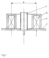
- the electrical field strength component has a maximum centrally, such as. B. the coupling pin or the E01 shaft in the circular waveguide.
- Fig. 2 shows the schematic structure of a microwave plasma cartridge with several magnets 3.1; 3.2; 3.3 and an associated jacket 4.1; 4.2; 4.3.
- a coupling arrangement 1 for the microwaves a circular waveguide of the E01 type is used in this case.
- the magnets 3.1; 3.2; 3.3 always have a mean diameter d larger by a wavelength ⁇ . Since the electrical field strength curve of the microwaves is periodically repeated towards the outside, the plasma is excited at several points.
- Such an embodiment of the microwave plasmatron is particularly well suited for large-scale arrangements.
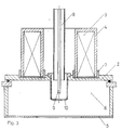
- a frequency of the microwaves of 2.45 GHz is used as a basis for determining the geometric dimensions, which corresponds to a necessary mean magnetic flux density of the static magnetic field of approximately 0.085 T for the ECR.
- the surface waveguide 2 is formed by a round flat plate, which is also a cover plate of the discharge space.
- the cover plate is made of aluminum.
- the magnet 3, which is designed here as a coil, is placed on the cover plate.
- the coil has an average diameter d of 12.5 cm, which corresponds approximately to the wavelength ⁇ of the microwaves.
- the width is about 1/4 ⁇ at 3 cm.
- the coil is enclosed by a U-shaped jacket 4 made of iron.
- the coil and the jacket 4 are inserted into the cover plate so that the areas of highest magnetic flux density are formed directly in the discharge space 6.
- Insulation 7 is introduced between the coil, the jacket 4 and the cover plate, so that with appropriate insulation of the discharge space 6 the plasma can be connected to high voltage potential, while the coil remains at ground potential.
- the microwaves are coupled into the discharge space 6 via the coaxial line 8 with an extended inner conductor as a coupling pin 9.
- the quartz glass beaker 10 is permeable to the microwaves, but takes over the vacuum separation of the discharge space 6 from the coupling point.
- the microwave plasmatron is attached to a discharge space 6 with a diameter of 250 mm and a height of 150 mm.
- the discharge space 6 is closed off at the bottom by the annular disk 5, as a result of which an improvement in the ignition behavior is achieved.
- the plasma In a pressure range of 10 ⁇ 2 Pa, the plasma is safely ignited at microwave powers of 400 W, regardless of the gas type, ion densities between 3 ... 10. 1010 cm ⁇ 3 can be determined. Ion currents with homogeneous current density distributions up to 3 mA / cm2 over 6 inches in diameter could be extracted from the plasma.
- a thin insulating material disc 11 is placed on the cover plate in the discharge space 6.
- the insulating washer 11 may only have a thickness of a few millimeters in this arrangement, the material used is Al2O3_ceramic.
- the cover plate with the insulating material disk 11 now forms the surface waveguide 2.
- the axial propagation of the electrical field strength component is restricted, and higher electrical field strengths are achieved in the region of the surface waveguide 2 near the surface.
- a similar effect occurs when the cover plate is given a structure as shown in FIG. 5. If the ribs 16 are very thin and their distance 15 is small compared to the wavelength ⁇ , the ribbed metal surface acts as a surface waveguide 2.
- the discharge space 6 shows the use of a microwave plasmatron for plasma excitation in an ion source.
- the discharge space 6 has a diameter of approximately 200 mm in the specified ion source.
- the gas inlet 12 is insulated above the cover plate.
- the discharge space 6 is lined with graphite inserts 13, to which the extraction system 14 is also attached.
- the magnetic flux density in the area of the extraction system 14 is so low ( ⁇ 0.01 T) that there is no disruptive influence on the ion extraction.
Landscapes
- Physics & Mathematics (AREA)
- Engineering & Computer Science (AREA)
- Plasma & Fusion (AREA)
- Chemical & Material Sciences (AREA)
- Analytical Chemistry (AREA)
- Plasma Technology (AREA)
- Chemical Vapour Deposition (AREA)
- Electron Sources, Ion Sources (AREA)
Claims (12)
- Plasmatron à micro-ondes destiné à engendrer une décharge de micro-ondes assistée par champ magnétique, se composant d'un espace de décharge, d'un agencement servant à coupler les micro-ondes dans l'espace de décharge et d'aimants, caractérisé en ce qu'un ou plusieurs aimants concentriques en forme de cylindre creux (3; 3.1; 3.2; 3.3), qui sont entourés par une enveloppe configurée en U (4; 4.1; 4.2; 4.3) par aimant en matière ferromagnétique, sont disposés sur un guide plan (2) d'ondes de surface d'une manière telle que le côté ouvert repose sur le guide (2) d'ondes de surface et l'agencement de couplage (1) de micro-ondes est monté au centre par rapport à l'aimant (3) en forme de cylindre creux.
- Plasmatron à micro-ondes selon la revendication 1, caractérisé en ce que le diamètre moyen (d) de l'aimant (3) en forme de cylindre creux correspond à une longueur d'onde ou à un multiple entier de la longueur d'onde des micro-ondes.
- Plasmatron à micro-ondes selon la revendication 1, caractérisé en ce que, lorsque plusieurs aimants (3.1; 3.2; 3.3) sont disposés, le diamètre moyen de chacun correspond à un multiple entier de la longueur d'onde des micro-ondes.
- Plasmatron à micro-ondes selon la revendication 1 ou 3, caractérisé en ce que les aimants en forme de cylindres creux (3.1; 3.2; 3.3) sont des bobines.
- Plasmatron à micro-ondes selon la revendication 1 ou 3, caractérisé en ce que les éléments en forme de cylindres creux (3.1; 3.2; 3.3) sont des aimants permanents.
- Plasmatron à micro-ondes selon l'un des revendications 1 à 5, caractérisé en ce que le guide (2) d'ondes de surface est réalisé sous la forme d'une plaque de recouvrement de l'espace de décharge (6).
- Plasmatron à micro-ondes selon l'une des revendications 1 à 6, caractérisé en ce qu'un mince disque (11) en matière isolante est posé sur le guide (2) d'ondes de surface.
- Plasmatron à micro-ondes selon la revendication 1, caractérisé en ce que le guide (2) d'ondes de surface est constitué d'une surface mécanisme nervurée.
- Plasmatron à micro-ondes selon la revendication 8, caractérisé en ce que le guide (2) d'ondes de surface comporte des nervures (16) dont les distances (15) sont faibles par rapport à la longueur d'onde.
- Plasmatron à micro-ondes selon la revendication 8 ou 9, caractérisé en ce que le guide (2) d'ondes de surface comporte des nervures (16) d'une épaisseur très faible par rapport à la distance (15) entre les nervures (16).
- Plasmatron à micro-ondes selon l'une quelconque des revendications précédentes, caractérisé en ce que l'espace cylindrique (6) de décharge est fermé par un disque annulaire (5).
- Plasmatron à micro-ondes selon l'une des revendications 1 à 9, caractérisé en ce que l'espace cylindrique (6) de décharge est fermé par un système plan (14) d'extraction.
Applications Claiming Priority (2)
| Application Number | Priority Date | Filing Date | Title |
|---|---|---|---|
| DD33887890A DD300723A7 (de) | 1990-03-20 | 1990-03-20 | Mikrowellen - Plasmaquelle |
| DD338878 | 1990-03-20 |
Publications (3)
| Publication Number | Publication Date |
|---|---|
| EP0448077A2 EP0448077A2 (fr) | 1991-09-25 |
| EP0448077A3 EP0448077A3 (en) | 1992-01-08 |
| EP0448077B1 true EP0448077B1 (fr) | 1995-08-16 |
Family
ID=5617191
Family Applications (1)
| Application Number | Title | Priority Date | Filing Date |
|---|---|---|---|
| EP19910104340 Expired - Lifetime EP0448077B1 (fr) | 1990-03-20 | 1991-03-20 | Plasmatron à micro-ondes |
Country Status (3)
| Country | Link |
|---|---|
| EP (1) | EP0448077B1 (fr) |
| DD (1) | DD300723A7 (fr) |
| DE (1) | DE59106238D1 (fr) |
Cited By (1)
| Publication number | Priority date | Publication date | Assignee | Title |
|---|---|---|---|---|
| DE102006037144A1 (de) * | 2006-08-09 | 2008-02-28 | Roth & Rau Ag | ECR-Plasmaquelle |
Families Citing this family (5)
| Publication number | Priority date | Publication date | Assignee | Title |
|---|---|---|---|---|
| DE4136297A1 (de) * | 1991-11-04 | 1993-05-06 | Plasma Electronic Gmbh, 7024 Filderstadt, De | Vorrichtung zur lokalen erzeugung eines plasmas in einer behandlungskammer mittels mikrowellenanregung |
| FR2724264B1 (fr) * | 1994-09-06 | 1996-10-18 | Commissariat Energie Atomique | Antenne cylindrique utilisable pour generer un plasma dans les conditions de resonance cyclotronique electronique |
| US5523652A (en) * | 1994-09-26 | 1996-06-04 | Eaton Corporation | Microwave energized ion source for ion implantation |
| RU2251824C1 (ru) * | 2003-09-22 | 2005-05-10 | Федеральное государственное унитарное предприятие "Научно-производственное предприятие "Контакт" | Сверхвысокочастотный плазмотрон |
| JP4944198B2 (ja) | 2007-06-11 | 2012-05-30 | 東京エレクトロン株式会社 | プラズマ処理装置および処理方法 |
Family Cites Families (2)
| Publication number | Priority date | Publication date | Assignee | Title |
|---|---|---|---|---|
| DE3729347A1 (de) * | 1986-09-05 | 1988-03-17 | Mitsubishi Electric Corp | Plasmaprozessor |
| KR880013424A (ko) * | 1987-04-08 | 1988-11-30 | 미타 가츠시게 | 플라즈머 장치 |
-
1990
- 1990-03-20 DD DD33887890A patent/DD300723A7/de unknown
-
1991
- 1991-03-20 EP EP19910104340 patent/EP0448077B1/fr not_active Expired - Lifetime
- 1991-03-20 DE DE59106238T patent/DE59106238D1/de not_active Expired - Lifetime
Cited By (2)
| Publication number | Priority date | Publication date | Assignee | Title |
|---|---|---|---|---|
| DE102006037144A1 (de) * | 2006-08-09 | 2008-02-28 | Roth & Rau Ag | ECR-Plasmaquelle |
| DE102006037144B4 (de) * | 2006-08-09 | 2010-05-20 | Roth & Rau Ag | ECR-Plasmaquelle |
Also Published As
| Publication number | Publication date |
|---|---|
| DE59106238D1 (de) | 1995-09-21 |
| EP0448077A2 (fr) | 1991-09-25 |
| EP0448077A3 (en) | 1992-01-08 |
| DD300723A7 (de) | 1992-07-09 |
Similar Documents
| Publication | Publication Date | Title |
|---|---|---|
| DE69020031T2 (de) | Radiofrequenzplasmaerzeugungsvorrichtung vom Koaxialkavitätstyp. | |
| DE69421033T2 (de) | RF induktive Plasmaquelle zur Plasmabehandlung | |
| EP0315986B1 (fr) | Source d'ions magnétron sans filament et son procédé d'utilisation | |
| DE3421530C2 (fr) | ||
| DE3854541T2 (de) | Verfahren und Vorrichtung zur Behandlung eines Materials durch Plasma. | |
| US6812647B2 (en) | Plasma generator useful for ion beam generation | |
| DE68921370T2 (de) | Electronzyklotronresonanz-Ionenquelle. | |
| DE3803355A1 (de) | Teilchenquelle fuer eine reaktive ionenstrahlaetz- oder plasmadepositionsanlage | |
| EP0486943B1 (fr) | Dispositif pour l'excitation d'un champ à micro-ondes uniforme | |
| DE7228091U (de) | Ionenquelle mit hochfrequenz-hohlraumresonator | |
| DE4319717A1 (de) | Vorrichtung zum Erzeugen planaren Niedrigdruckplasmas unter Verwendung einer Spule mit deren Achse parallel zu der Oberfläche eines Koppelfensters | |
| DE4235914A1 (de) | Vorrichtung zur Erzeugung von Mikrowellenplasmen | |
| DE19812558B4 (de) | Vorrichtung zur Erzeugung linear ausgedehnter ECR-Plasmen | |
| DE69405546T2 (de) | Lineare mikrowellenquelle zur plasmabehandlung von flächen. | |
| US4687616A (en) | Method and apparatus for preventing cyclotron breakdown in partially evacuated waveguide | |
| JPS61502788A (ja) | マイクロ波電子銃 | |
| EP0448077B1 (fr) | Plasmatron à micro-ondes | |
| DE4431231C2 (de) | Insbesondere als ein relativistisches Magnetron geeignetes Magnetron | |
| DE102004043967B4 (de) | Anordnung und Verfahren zur Plasmabehandlung eines Substrates | |
| DE69210501T2 (de) | Elektroncyclotionresonanz-Ionenquelle vom Wellenleiter-Typ zur Erzeugung mehrfachgeladenen Ionen | |
| DE69025128T2 (de) | Magnetrone | |
| DE4239843A1 (de) | Vorrichtung für die Erzeugung von Plasma, insbesondere zum Beschichten von Substraten | |
| WO1994003919A1 (fr) | Procede de production de faisceaux de n'importe quels ions hautement charges, de faible energie cinetique et dispositif de mise en ×uvre dudit procede | |
| DE1523101A1 (de) | Mikrowellen-Hohlraumresonator | |
| DE2735299A1 (de) | Elektrisch angeregter gaslaser |
Legal Events
| Date | Code | Title | Description |
|---|---|---|---|
| PUAI | Public reference made under article 153(3) epc to a published international application that has entered the european phase |
Free format text: ORIGINAL CODE: 0009012 |
|
| AK | Designated contracting states |
Kind code of ref document: A2 Designated state(s): CH DE FR GB LI NL |
|
| PUAL | Search report despatched |
Free format text: ORIGINAL CODE: 0009013 |
|
| AK | Designated contracting states |
Kind code of ref document: A3 Designated state(s): CH DE FR GB LI NL |
|
| 17P | Request for examination filed |
Effective date: 19920707 |
|
| 17Q | First examination report despatched |
Effective date: 19940427 |
|
| GRAA | (expected) grant |
Free format text: ORIGINAL CODE: 0009210 |
|
| AK | Designated contracting states |
Kind code of ref document: B1 Designated state(s): CH DE FR GB LI NL |
|
| PG25 | Lapsed in a contracting state [announced via postgrant information from national office to epo] |
Ref country code: GB Effective date: 19950816 Ref country code: FR Free format text: THE PATENT HAS BEEN ANNULLED BY A DECISION OF A NATIONAL AUTHORITY Effective date: 19950816 Ref country code: NL Free format text: LAPSE BECAUSE OF FAILURE TO SUBMIT A TRANSLATION OF THE DESCRIPTION OR TO PAY THE FEE WITHIN THE PRESCRIBED TIME-LIMIT Effective date: 19950816 |
|
| REF | Corresponds to: |
Ref document number: 59106238 Country of ref document: DE Date of ref document: 19950921 |
|
| EN | Fr: translation not filed | ||
| NLV1 | Nl: lapsed or annulled due to failure to fulfill the requirements of art. 29p and 29m of the patents act | ||
| GBV | Gb: ep patent (uk) treated as always having been void in accordance with gb section 77(7)/1977 [no translation filed] |
Effective date: 19950816 |
|
| PG25 | Lapsed in a contracting state [announced via postgrant information from national office to epo] |
Ref country code: LI Effective date: 19960331 Ref country code: CH Effective date: 19960331 |
|
| PLBE | No opposition filed within time limit |
Free format text: ORIGINAL CODE: 0009261 |
|
| STAA | Information on the status of an ep patent application or granted ep patent |
Free format text: STATUS: NO OPPOSITION FILED WITHIN TIME LIMIT |
|
| 26N | No opposition filed | ||
| REG | Reference to a national code |
Ref country code: CH Ref legal event code: PL |
|
| PGFP | Annual fee paid to national office [announced via postgrant information from national office to epo] |
Ref country code: DE Payment date: 20100409 Year of fee payment: 20 |
|
| REG | Reference to a national code |
Ref country code: DE Ref legal event code: R071 Ref document number: 59106238 Country of ref document: DE |
|
| PG25 | Lapsed in a contracting state [announced via postgrant information from national office to epo] |
Ref country code: DE Free format text: LAPSE BECAUSE OF EXPIRATION OF PROTECTION Effective date: 20110320 |